In this article I have explained how to build a simple room ionizer circuit for getting a clean, pollution free environment right inside our home.
Introduction
Have you ever thought or wondered why atmosphere over hill stations and other similar places which are far away from modern cities give you a feeling of freshness and good health?
The answer is simple, the air in such places are free from pollutants and harmful chemicals like smoke and gases.
WARNING: THE CIRCUIT EXPLAINED IN THIS ARTICLE IS NOT ISOLATED FROM MAINS AC, AND IS THEREFORE EXTREMELY DANGEROUS TO TOUCH IN OPEN AND UNCOVERED CONDITION. NECESSARY PRECAUTIONS TO SAFEGUARD FROM AN ELECTRIC SHOCK IS STRICTLY RECOMMENDED. ALTHOUGH THE WORKING OF THE CIRCUIT IS TESTED, THE HEALTH BENEFITS OF THIS IONIZER CIRCUIT HAVE NOT BEEN VERIFIED BY THE AUTHOR. IF YOU ARE BUILDING THIS PROJECT, YOU AGREE THAT YOU ARE BUILDING IT AT YOUR OWN RISK.
A Must for City Like Delhi
Delhi, the capital of India is today severely struggling with air pollution crises. The issue has become so serious that it has been entitled as the highest priority among all the other ongoing health issues, and has reached an emergency level.
Although tough efforts are being implemented, still it seems the conditions isn't improving a bit, in fact the situation is getting even grimmer by the day.
A cheap solution like the proposed room air ionizer seems to be a very handy tool which can not only help control Delhi pollution, but also provide individual houses with reasonably pure air. This equipment can be used in houses, as well as in cars for the intended remedy.
Well, if you are settled in one of those cities which is engulfed with bad air and if you have compromised with the situations, here's your chance to get rid of the situation through the circuit I have explained below:
What is an Air Ionizer - How it Works
An air ionizer or as some may refer it as a room ionizer is basically a device or electronic circuit which is designed for generating voltage at the level of kilo-volts for implementing the said ionizing effects. So what's ionizing after all?
The high voltage that's generated from an ionizer is actually tuned for generating a negative voltage, at around minus 4 kV. This high negative voltage is allowed to get terminated over an open ended sharp conductor tip or point that's sharply carved.
When the voltage reaches at this sharp point, it tends to continue its forward motion and gets shot or released into the air in the form of negatively charged ions.
Once in the air these ions become free to move around and start getting dispersed across the room or the premise, as more and more ions are released from the air ionizer device.
Now as these ions roam freely in the air it comes across and starts colliding with the already present pollutants like dust particles, smoke/gas particles etc in the air.
As per the rules all particles and all materials present around should be positively charged, so what happens, the oppositely charged ions starts collecting these pollutants from the air by attracting them toward them (opposites attract), just as a magnet bar would do to iron pins.
The pollutants in the air slowly find themselves pulled and firmly stuck over these ions until each of the ions become so much pollutant laden and heavy that they start crashing on the ground or if they find a wall nearby they start gathering on it.
In this way the air in the course of time becomes absolutely clean and free from all impurities.
Circuit Operation
The circuit is quite simple and can be built even by a layman, having just basic knowledge of electronics.
The circuit is fundamentally based on Cockroft-Walton Ladder Network, The concept makes use of a network of many diodes and capacitors arranged in such a way that the applied voltage to it gradually becomes stepped up to very high levels, in the order of around 10kV,
However a 10kV range is not suitable for the discussed ionizing effects, in fact at this level the effect might produce opposite results.
If we go by calculations the present design would also generate around -10kV, spoiling the intended cause, however practically it is found to be dropping to about -4kV.
This reduction happens due to radiation losses, because in the course of its stepping up, the voltage tends to spark through emissions across the PCB until finally the resultant voltage at the output tip of the device reaches only up to around -4kV which is by God's grace the exact level for achieving the ionizing effect.
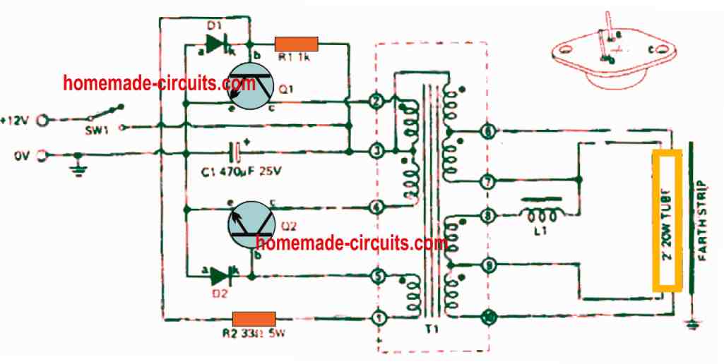
Circuit Diagram
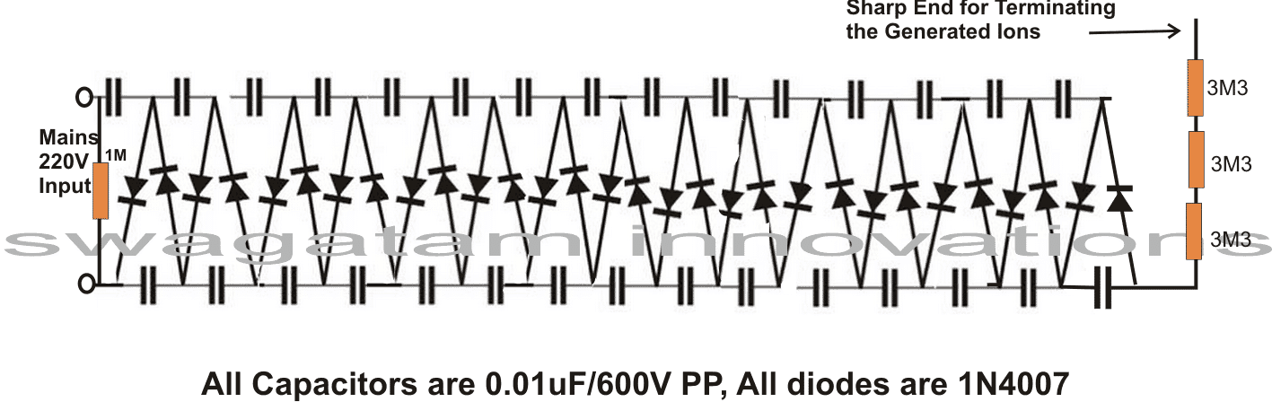
The entire circuit may be built over a general purpose board, by soldering the shown number of capacitors and diodes exactly in the way they are arranged in the diagram.
Following the diagram pattern would make the making easier to assemble and would produce guaranteed results without faults.
After the circuit is assembled, check the entire board for any wring connections, this is important because the circuit is very critical with its polarities, a single wrongly connected diode would make the results zero.
After proper confirmation, the soldered side should be thoroughly cleaned with thinner so that no residual flux stays deposited causing loss of voltage and reduction in the desired effects.
The end which is terminated for releasing the ions must be needle shaped, preferably a small pin or needle can be used there for enabling perfect prorogation of the ions.
After all the above precautions are complete, it's time to power the unit. Be extremely careful, as the entire circuit is connected directly with mains AC and can be life threatening if touched in the powered position.
Verifying the Working of the Circuit
Once the circuit and if hopefully everything is rightly done with the assembly, you would hear a "hissing" noise near the tip of the releasing pin point. The area near the tip of the pin would give you a cooler sensation like a cool breeze flowing out.
The point would also produce a fish like smell.....all the above indications would confirm that the unit is working right and you are already breathing fresh air around your nose and heading toward a healthy life.
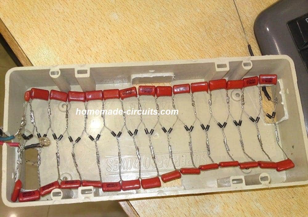
THE ABOVE CIRCUIT WAS SUCCESSFULLY BUILT AND TESTED BY ONE OF THE KEEN FOLLOWERS OF THIS BLOG, MR. ALI ADNAN.
THE FOLLOWING BEAUTIFUL PICTURES WERE SENT BY HIM.
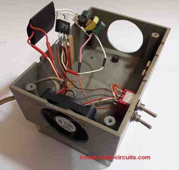
Prototype Pictures

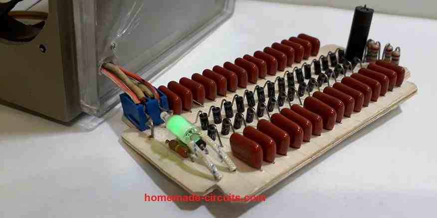
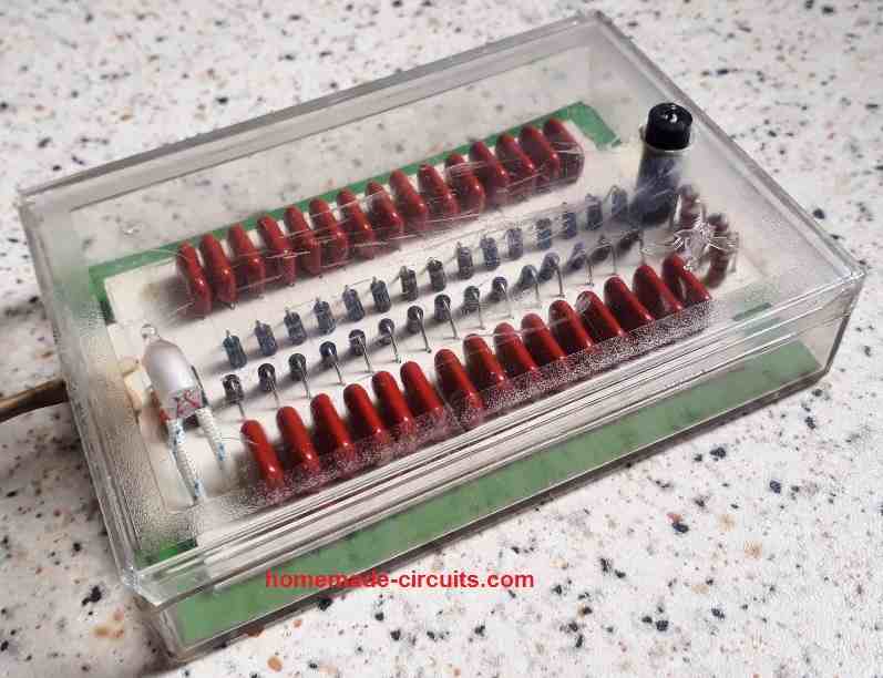
The above room ionizer circuit was also successfully built and implemented by one of the dedicated readers of this blog "Ersa". The following tested working prototype images were sent by Ersa for our viewing pleasure.


Questions & Answers
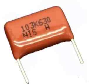
Hi. Great project, I want to make my ionizer. So, the value of the caps are 630V103J (if I read correctly) but the size ? are 1 cm ?
Hi, thanks, glad you liked the project, that’s right, the capacitors should be 0.01uF/630 V rated ideally, and must be PPC type.
Hi Sir.
Is this type of capacitor the right one?
630V103J 0.01UF Pitch 10MM 10NF 630V 103 CBB Polypropylene film capacitor.
Thanks
Hi Rosario,
it looks OK to me but physically these must be exactly similar to the ones which are shown in the prototype images.
Good day sir. I want to try the construction of the air ionizer circuit for home, but I have a question.
Is -4kV dangerous to human life or kills when the needle is mistakingly touched?
Hello Emmanuel,
According to the previous information I could gather -4kv is good for health. However I have not verified the results so cannot confirm the results. The needle will not produce an electric shock due to the presence of the high value series resistors.
Please read the warning message at the start of the article before trying this circuit.
Ok. Thanks so much.
Dear Sir Swagatam
Hello
Referring to your notice denoting “please keep up the good work”, I am going to send you pictures of your room air Ionizer circuit that I made one year ago. I hope that my experiences would be useful for your visitors.
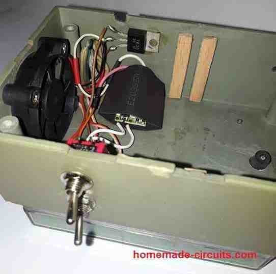
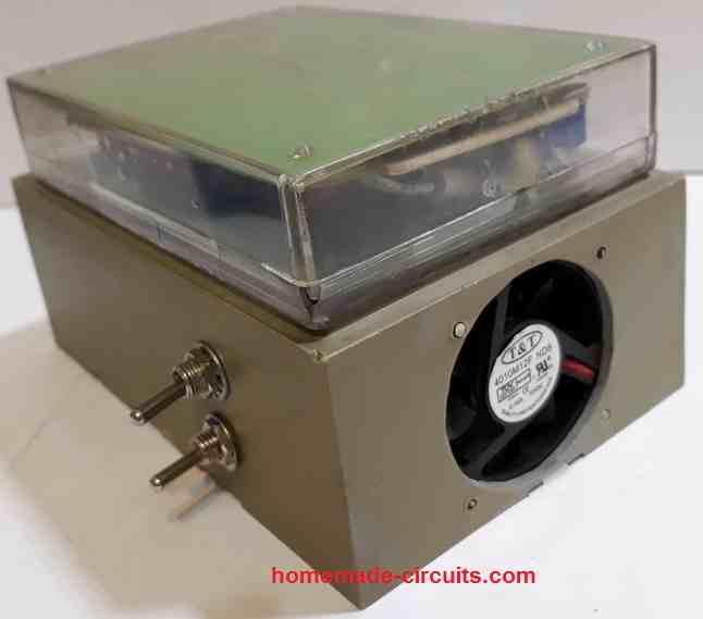
After a month passed from working the circuit, I noticed that everything around the unit including curtains, wall, etc., had been covered with a black layer and I found that the origins of it were, Charged ionized particles floating in the air. In order to solve the problem I inserted the needle of the ion spreading into a plastic box, I made two nos of 5 cm diameter holes on both sides of the box for the air to enter and exit; I accommodated a 12v dc fan on one side of the box and a piece of facial tissue inside the box to absorb the ionized particles and do not let them to spread in the air and make black and dirty everything around the air room ionizer unit. In order to reduce the sound of the fan, I reduced the speed of it which worked with the help of a 15v 300mA dvd driver, I added a 8v regulator IC to the unit
Everything is good now and I am very satisfied with it. I thank you so much for your very good circuit.
Wish you all the best
Ersa
Thank you so much Ersa,
I saw the pics and they look amazing.
Yes the black color deposit is due to the dust particles which get attracted by the negative ions and stick to the nearest neutral background which happens to be the walls or the carpets. I am glad you could modify the prototype and very intelligently solve the problem, and I am happy that everything is running smoothly now.
I will surely check out the diagrams and upload in the above article soon.
Again please keep up the good work 🙂
Dear Sir Swagatam
Hello. Thank you very much for encouraging me and I thank you so much for publishing the pictures and that you described scientifically the reason why dust particles, including carbon particles stick to environmental things.
I praise you for being so kind and generous, and wish you long-lasting joy and health.
Best regards
Ersa
Thank you so much Ersa,
Wish you all the best and God bless you!
how many volts is the high voltage?
I have a design with 30 diodes and 30 capacitors. Can I put more?
It is -4kv. If you put more diodes the output voltage may increase beyond -4kv and then it won’t serve the room ionizer purpose
I feel 1M Resistor should be in series with the Circuit. It is Shown across two input lines & may this Short the
Circuit. KINDLY CONFIRM
Actually there should be a series neon lamp with the 1M resistor which is mistakenly not shown in the diagram. However, even if you connect a 1M directly across the mains it will not create a short circuit because 1M is a very large value and will have no effect on the circuit.
Dear Sir Swagatam Thank you very much for sharing your knowledge
Kind regards
Ali
You are welcome Ali!
Hi Sir Swagatam. I want to assemble this circuit in a way that I can get more power (current) at the output. would you please tell me how much could be the utmost value of capacitors. I think 1N4007 diodes would be perfect for capacitors with more value.
Thank you in advance
Regards
Ali
Hi Ali, increasing capacitor value might result in the circuit producing ozone instead of negative ions, so it won’t be a good idea to increase capacitor value. Instead you can build many of these units and use them together for getting the desired amplified results.
Hi Sir Swagatam. I have recently read somewhere that ozone gas smells like fresh garlic. Isn’t it a good idea to build one on breadboard and smell it? may be the problem would be solved for ever Sir
Kind regards
Hi Ali, According to me ozone gas or any ionic gas produce smell of a rusted wet iron….so I am not sure about the garlic like smell
Hi, Thanks for providing the nice negative ion making circuit and explanation. Can I use it in cleaning of positively charged cat’s hair from my cloth or mat, will this device help me in that work.
Regards
Hi, thanks for liking the post! I don’t think the ions produced by the unit will be so powerful to lift and clean cat’s hair. It is designed to clean only microscopic particles, a cat’s hair looks to big to be attracted by this circuit.
Perfect, thank you for replying Swagatam!
I just have one more question… what do I use to connect the energy flowing from the adapter/transformer to the circuit/capacitor board?
Hope you’re having a nice day again 🙂
You are most welcome, the inverter output can be connected to the ionizer through a pair of ordinary flexible copper wires. Or simply the transformer output wires can itself be directly hooked up with the ionizer supply input
Good morning Swagatam,
I’m not sure if this discussion forum is still active, but I would GREATLY appreciate a response!
I find your instructions and insight for this project to be super useful as I have been searching for a way to build a working negative-ion generator for quite a while!
Even though I will be able to access both the diodes and the capacitors, I’m a little confused about the energy source. Would it be possible for me to use a battery for this experiment, or does the generator need to be plugged into a wall?
Finally, this is a science experiment for one of my classes, so do you suggest any tips or tricks to make this work more effectively since it’s been over a year since this article was published?
Thank you very much 🙂
Thank you Aubrey, and glad you liked the post.
The circuit must be built exactly as shown, using the exact components as indicated in the diagram, unfortunately there are no tricks to make it work more effectively, except increasing or deceasing the output voltage, which can be done by increasing or reducing the capacitor/diode stages accordingly.
I found the capacitor to be very crucial, and it must exactly the ones shown in the diagram. Once I tried making the project using ceramic 1kv type capacitors and it simply failed to work.
You can use a lead acid battery, but the battery power will need to be first converted to an AC, and then fed to the ionizer circuit.
One example concept can be found in the following article:
Make this Car Air Ionizer Circuit
Hi Swagatam
Thanks for the info on the LED indicator just saw the circuit, nice
All the best to you
Regards
Vee
Thank you Vee, hope it serves the intended purpose!
Hi Swagatam
I have an Air purifier for my bedroom and its plugged into a smart plug which is programmed to come ON at night and switch OFF in the morning.
As this unit runs very silent I am not sure whether its ON on not, so I want to add an LED as an indicator, so can you help me with a circuit for adding the same to the 120VAC supply to this unit
Thanks
Vee
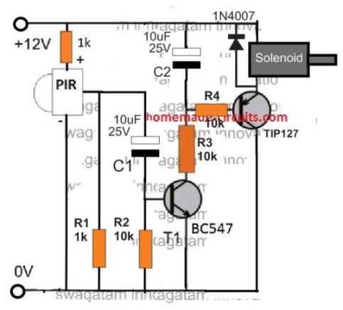
Hi Vee,
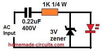
you can try the following circuit:
Please remember that the circuit is not isolated from the mains, therefore it can be extremely dangerous to touch it in the powered condition.
Can i connect more needle points… say 4 in total paralled with the one in cct but spaced apart. Also the neon indicator lamp is not shown in the cct diagram but is seen in the photograph i presume this lamp is connected across the mains input via a suitable current limiter resistor.
…..yes the neon is optional and is connected across the mains AC lines
More needle points will reduce the transmitting intensity of the needles, proportionately…
The mk3 is on the bench, using 30x 220nF caps. I’ll keep you posted.
I haven’t decided whether to use 1 or 2 carbon brushes yet.. The mk2 has 2 brushes and is fantastically powerful, but I wonder whether it would have been even better with only 1, as the mk1 had.
I made 2 like the mk1 (22nf x 24), adding a switch to the 2nd (before retrofitting switches to all 3) and higher resistance (40M) at the HV end, as the first (with 20M) was not reducing the current quite enough to be unnoticeable when touching the output!
I have 40M on the mk2 (100nF x 30) and even then it’s a bit tasty!
Also thanks Abu-Hafss for the sim. Very valuable!
I changed the Max input voltage to 340, as this is the peak to peak which gives RMS of 240V, as UK mains supply value.
I’ve added a switch to each now, as per your simulation circuit, after getting zapped by the plug pins one too many times! I used dpst on live and neutral as the caps will discharge (through you) via either pin..
Thankyou for this Swagatam!
I have built several of these in the last month or so, the first with 24x 22nF caps (12 stage) the 2nd with 30x 100nF – this mk2 version is extremely powerful. The voltage in the air near the emitters reaches over -120V, compared to around -3V max from my shop bought PureMate one! (the mk1 with 22nF, even, reads around -50V)
I used carbon fibre brushes for the emitters which gives a massive improvement over using needles. I just bought some non-woven carbon fibre tape and made the brushes using BigClive’s method.. I got this idea originally from a small car ioniser I have (AirTamer) which is very high output compared to my other commercially available (needle) ones. However, even the AirTamer’s output is nowhere near these DIY versions, at about -5V, simply measured in the air with a grounded multimeter.
I epoxied all of the solder joints, as any sharp edges will produce unwanted ionisation within the box, and reduce the desired output. I wonder if this is the reason these are so much more powerful than the commercial ones..? It is otherwise essentially the same circuit (mountain breeze, etc.)
You are welcome Jose,
Actually the output current from the device is extremely low, may be in microamps, so I doubt if this potential is measurable with a DMM. The current is too low to sustain through the probes of the meter.
Yes that’s right, the black air tight insulation sealing all around the PCB and the circuit drastically helps in improving the emission power of the unit
Hi, thanks for the quick reply. I too would have thought it unlikely to be able to measure the voltage in the air but it is indeed possible! I’ll send you a video clip if you like (email?)
I’ve seen other people’s videos where they attach an antannae of sorts (copper or other metallic sheet, croc clipped to the DMM lead) but I find this makes little difference to the reading – the potential can be measured directly with the probe.
Hi, yes it may be possible but the results won’t be correct on the meter. Because, the emitter is indeed emitting upto -4kv which is difficult to capture and check on the general purpose meters.
I agree entirely, it is not an accurate or meaningful measurement of output as such, but rather it is an indication of the relative power of this one compared to the ones I bought. The PureMate (PM-100) measured between -2v or -3V at about 1 cm away from the needles, but this reading would drop quite quickly. The mk1 version I made measures around -50v DC at same 1 cm distance – and this value drops much more slowly. The mk2 (100nf x 30) measures a sustained -120V at 1cm.
The PureMate one, however, has a gounded plate in front of the needles to increase the ‘ion wind’, with holes for the points to partially poke through, and the ozone generated thus is quite high! (This method is used in pure ozone generators, as it increases the strength of the corona discharge – but also reduces the negative ion output as a lot of the charge is dissipated through the grounded plate). I modified that PureMate one, disconnecting the grounded plate, rearranged the needle assembly infront of the plate which also mounted the needles via insulated bushings, and added carbon fibre tips instead. The output wasn’t increased all that much (still around -3V max.) but there was a massive reduction in the ozone smell…
All the best, Jose
OK, thanks for the interesting feedback!
Hello, I could not set up the circuit with proteus. If you have installed from another program before, can you throw it? 🙂
Hello, I built it practically with real parts, did not simulate.
Hello, I made this project with,
30x 22nF 630v
30x 1N4007
1x 4.7mOhm resistor before the needle
Powered by 220v ac.
However some of the caps burned in the first try. I dont know where did I make a mistake? Can anyone help me to fix that?
Hi, the capacitor cannot burn, they should be virtually indestructible with their 630 V rating, I think your caps may be faulty or duplicate quality…
is there any range?i mean can it purify a entire house?if it does how much time it would take on average consider a regular room size.
The results are actually time dependent and how well the room is sealed from all sides. For quicker results you may have to install at least one unit per wall
for a small room closed from all sides may take up to 5 hours to clean up
Hi, No, 275 V will not work, it should be over 600 V, and also it should metallized polyester type.
The LIVE/Neutral orientation does not matter, you can put the inputs any way round