The proposed infrared or IR remote control circuit can be used to operate an appliance ON/OFF through any standard TV remote control handset.
In this write up I have explained a couple of these simple infrared remote control circuits designed for controlling any given electrical appliance through an ordinary or TV remote control unit.
Introduction
Controlling household electrical gadgets or any electrical equipment remotely can be fun.
Controlling gadgets like a TV set or a DVD player through a remote may look pretty common to us and we are very used to with the experience, however for controlling many other domestic equipment like a water pump, lights etc we are compelled to walk around for implementing the switching.
The article is inspired by our usual TV remote concept and has been applied for controlling other house hold electrical appliances remotely.
The circuit facilitates and helps the user to do the operations without moving an inch from his resting place.
The whole circuit of the proposed IR remote control may be understood by studying the following points:
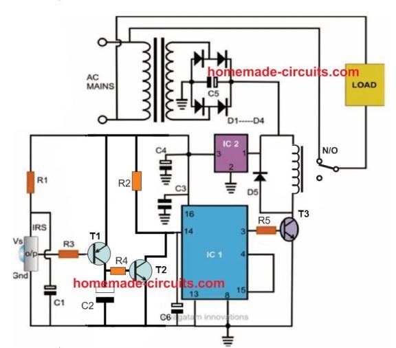
Referring to the figure, we see that the entire layout consists of just a couple of stages viz: the IR sensor stage and the flip flop stage.
Thanks to the highly versatile, miniature IR sensor TSOP1738 which forms the heart of the circuit and directly coverts the received IR waves from the transmitter unit into the relevant logic pulses for feeding the fllip flop stage.
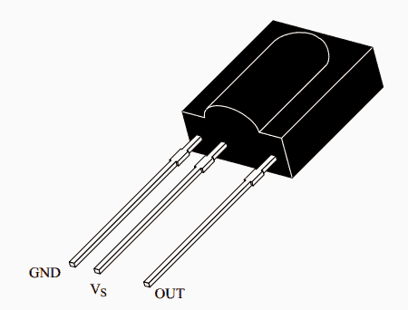
The sensor basically consists of just three leads viz: the input, the output and the biasing voltage input lead. The involvement of only three leads makes the unit very easy to configure into a practical circuit.
The sensor is specified for operating at 5 volts regulated voltage which makes the inclusion of the 7805 IC stage important.
The 5 voltage supply also becomes useful for the flip flop IC 4017 and is appropriately supplied to the relevant stage.
When a IR signal becomes incident over the sensor lens, the inbuilt feature of the unit activates, triggering a sudden drop in its output voltage.
The PNP transistor T1 responds to the negative trigger pulse from the sensor and quickly pulls the positive potential at its emitter to the collector across the resistor R2.
The potential developed across R2 provides a positive logic high to the IC 4017 input pin #14. The IC instantly flips its output and changes it’s polarity.
The transistor T2 accepts the command and switches the relay according to the relevant input provided to its base.
The relay thus switches the connected load across its contacts alternately in response to the subsequent triggers received from the IR transmitter unit.
For the sake of convenience the user may use the existing TV remote control set unit as the transmitter for operating the above explained control circuit.
The referred sensor is well compatible with all normal TV or DVD remote control handset and thus can be appropriately switched through it.
The entire circuit is powered from an ordinary transformer/bridge network and the entire circuit may be housed inside a small plastic box with the relevant wires coming out of the box for the desired connections.
Must Read for you: How to Control Appliances using TV Remote
Circuit Diagram
Video Demonstration
Parts List
The following parts will be required for making the above explained infra red remote control circuit:
- R1 = 100 ohms,
- R3 = 1K,
- R2 = 100K,
- R4, R5 = 10K,
- C1, C2, C4 = 10uF/25V
- C6 = 100uF/25V
- C3 = 0.1uF, CERAMIC,
- C5 = 1000uF/25V,
- T1 = BC557B
- T2, T3 = BC547B,
- ALL DIODES ARE = 1N4007,
- IR SENSOR = TSOP1738 image: Vishay
- IC1 = 4017,
- IC2 = 7805,
- TRANSFORMER = 0-12V/500mA,
TSOP1738 pinout Details
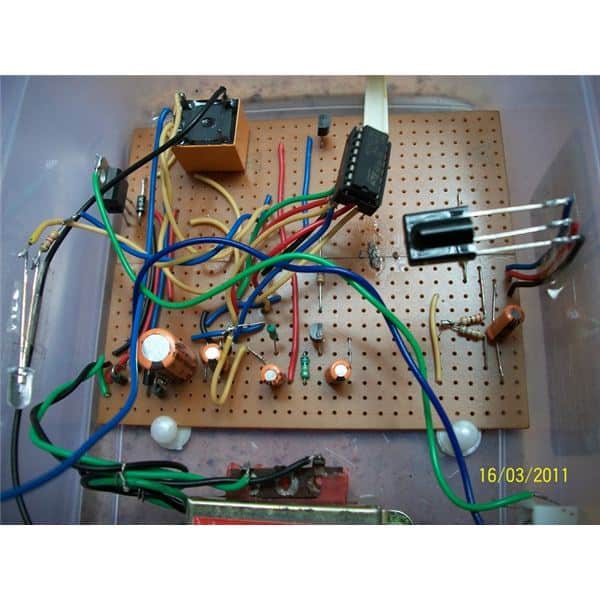
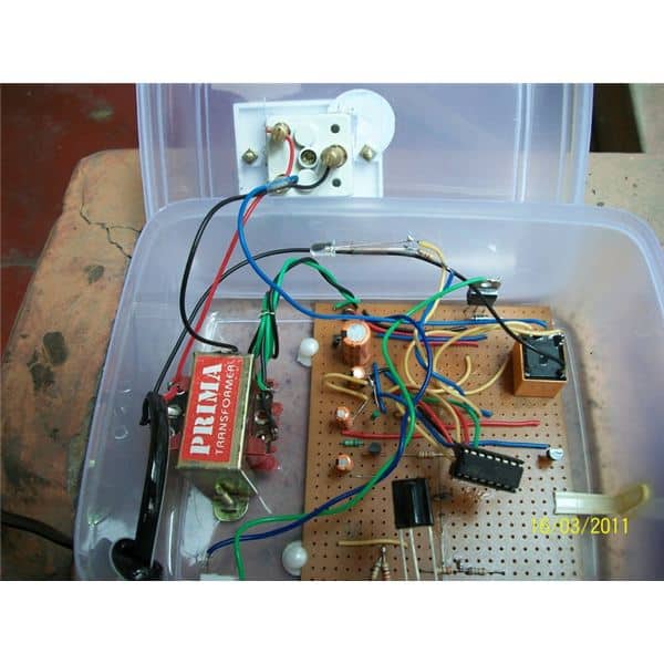
Prototype image courtesy: Raj Mukherji
2) Precision Infrared (IR) Remote Circuit
The second IR remote control circuit discussed below uses a unique frequency and detects only the specified IR frequency from the given remote transmitter unit, making the design entirely failproof, accurate and reliable.
Ordinary IR Remote Drawback
Ordinary IR remote control circuits have one big drawback, they easily get disturbed by stray external frequencies, and thus produce spurious toggling of the load.
In one of previous posts I have discussed a simple IR remote control circuit which operates quite well, however the circuit is not completely immune to external electrical disturbance generations such as from appliance switching etc. which results in false operations of the circuit causing lot of annoyance to the user.
The circuit design included here efficiently overcomes this problem without incorporating complex circuit stages or microcontrollers.
Why LM567 is Used
The solution comes easily due to the inclusion of the versatile IC LM567.
The IC is a precise tone decoder device which can be configured to detect only a specified band of frequency, known as passband frequency.
Frequencies not falling within this range will have no effect on the detection procedures.
Thus the passband frequency of the IC may be set precisely at the frequency generated by the transmitter IR circuit.
Shown below are the Tx (transmitter) and the Rx (receiver) circuits which are set precisely to complement one another.
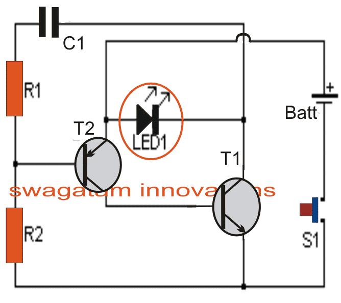
T1 ad T2 along with R1, R2 and C1 in the first Tx circuit forms a simple oscillator stage which oscillates with a frequency determined by the values of R1 and C1.
The IR LED1 is forced to oscillate at this frequency by T1 which results in the transmission of the required IR waves from LED1
As discussed above, R5 of IC2 in the Rx circuit is adjusted such that its passband frequency precisely matches with that of LED1 transmission output.
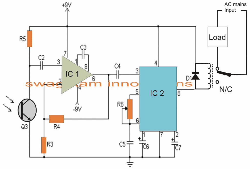
Circuit Operation
When the Tx IR waves are allowed to fall over Q3 which is an IR photo transistor, a subsequent order of varying positive pulses is applied to pin#3 of IC, which is basically configured as a comparator.
The above function generates an amplified output at pin#6 of IC1 which in turn gets induced across the input or the sensing pin out of IC2.
IC2 instantly latches on to the accepted passband frequency, and toggles its output at pin#8 to a low logic level, triggering the connected relay, and the preceding load across the relay contacts.
However the load would stay energized only as long as Tx stays switched ON, and would switch OFF the the moment S1 released.
In order to make the output load latch and toggle alternately, a flip flop circuit will need to be employed at pin#8 of IC2.
Parts List
- R1 22K 1/4W Resistor
- R2 1 Meg 1/4W Resistor
- R3 1K 1/4W Resistor
- R4, R5 100K 1/4W Resistor
- R6 50K Pot
- C1, C2 0.01uF 16V Ceramic Disk Capacitor
- C3 100pF 16V Ceramic Disk Capacitor
- C4 0.047uF 16V Ceramic Disk Capacitor
- C5 0.1uF 16V Ceramic Disk Capacitor
- C6 3.3uF 16V Electrolytic Capacitor
- C7 1.5uF 16V Electrolytic Capacitor
- Q1 2N2222 NPN Silicon or Transistor 2N3904
- Q2 2N2907 PNP Silicon Transistor
- Q3 NPN Phototransistor
- D1 1N914 Silicon Diode
- IC1 LM308 Op Amp
- ICIC2 LM567 Tone Decoder
- LED1 Infa-Red LED
- RELAY 6 Volt Relay
- S1 SPST Push Button Switch
- B1 3 Volt Battery Two 1.5V batteries in series
- MISC Board, Sockets For ICs, Knob For R6,
- Battery Holder
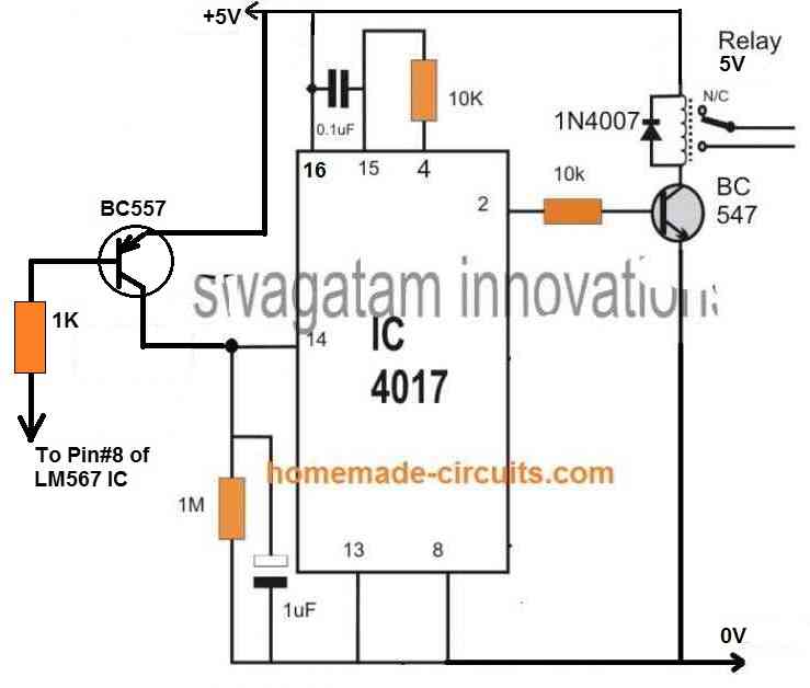
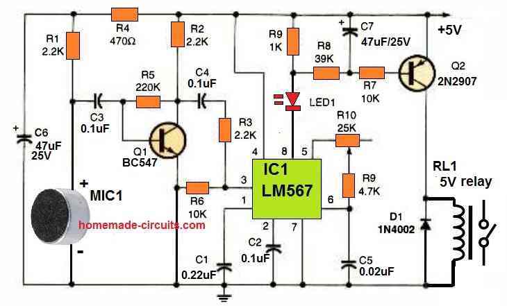
Another Simple LM567 based IR Remote Control Circuit
The next accurate LM567 based IR transmitter/receiver circuit ensures that the remote control can be operated only through a preset fixed frequency, and will not operate through any other unknown frequency.
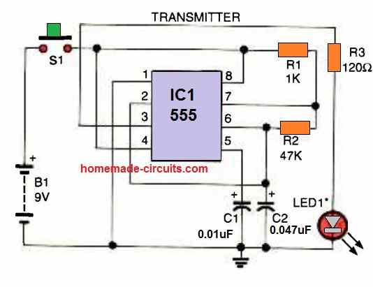
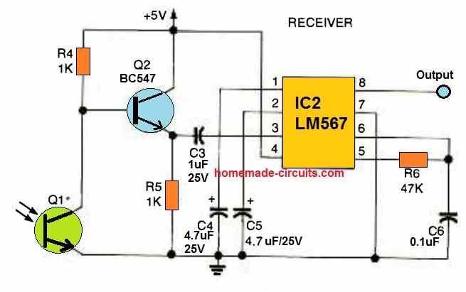
The transmitter circuit shown above produces IR light pulses through LED1, with a 320 Hz frequency (set by R2).
This frequency is focused at the phototransistor Q1 of the receiver circuit. This causes the phototransistor's collector to oscillate at the same 320 Hz frequency.
This frequency is boosted by the BC547 transistor and applied to the input pin#3 of the IC LM567.
The LM567 detects the 320 Hz signal as soon as it reaches the phototransistor, which instantly causes the output pin#8 of LM567 to turn low.
If the pulses of some other frequency is focused to the phototransistor, the LM567's output stays high and unresponsive, because it is calibrated to respond only for 320 Hz (as set by R6).
If you wish to operate the remote control with some other frequency, make sure to use identical values for R2 and R6, so that the transmitter frequency matches the receiver's detection frequency.
Remember that the LM567 operates between 100 Hz and 1 kHz and the detection frequency range must not be selected beyond these limits.
A multi-channel remote control system may also be created by substituting R2 with additional number of resistors (for multiple frequencies) and LM567s set to the desired frequencies.
Switching an Output Load
If you want to switch an output load ON/OFF at pin#8 of the LM567, you can do it by integrating a 4017 IC flip flop circuit with pin#8 of LM567.
To implement this you just have to integrate the following 4017 flip flop relay circuit with pin#8 of the LM567 circuit explained above.
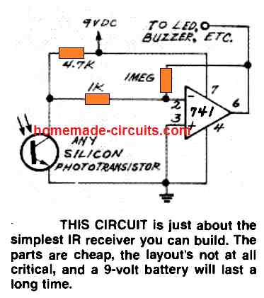
Simple Infrared Receiver using IC 741
Infrared Remote Control Circuit using IC 555 and Transistors
Here's a straightforward infrared switch designed for remote control purposes. It utilizes a typical IR LED and IR diode detector pair, specifically the CGIY89A/BPW50 components.
Transmitter Circuit
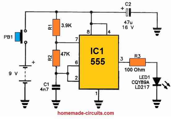
The 555 IC based IR transmitter circuit generates a series of pulses to drive the IR LED.
IR Receiver
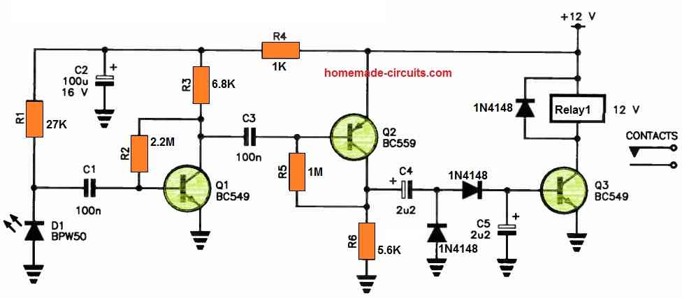
These pulses are then picked up by the IR receiver circuit through the BPW50 IR sensor and subsequently amplified by a high-gain amplifier, employing Q1 and Q2.
The output from Q2 undergoes rectification via a voltage-doubler rectifier, which supplies the base current required for the relay driver, Q3, ultimately enabling relay operation.
The transmitter is enclosed within a compact handheld enclosure, powered by a 9 V transistor radio battery.
In contrast, the receiver is powered by a 12 V DC source, such as a plug-in adapter. It's worth noting that all the components used in this setup are readily available at electronics retailers.


Questions & Answers
Hello Sir.
I have a project proposal to construct an AUTOMATIC DOOR BELL that uses IR sensors. So it works in that; when an individual happens to appear at the door, the one inside is audibly notified. But now, this alert is to appear also as a notification on phone. How do I go about this Sir?
Hello Jedidiah,
Sending the alert on a smart-phone will require an Arduino GSM circuit. You can try modifying one of the following concepts accordingly, and check the response:
https://www.homemade-circuits.com/?s=SMS
“Infrared Remote Control Circuit using IC 555 and Transistors”:
1. could you provide the mathematics part of how you found the values of different components (resistors, capacitors, and so on) in the transmitter circuit and IR receiver circuit?
2. Could you explain why you used a relay on the IR receiver?
3. Is there a way to simplify the IR receiver such that we do not use a relay? if yes, please provide a new schematic of the IR receiver (use cheap components for cost effective).
4. Would it be possible to modify the IR receiver schematic and also use an IC 555 as well?
I AM WORKING ON A PROJECT TO BUILD A “SIMPLE IR REMOTE CONTROL” PCB AND TEST IT, BUT THE TOTAL BUDGET IS LIKE $35. SO, I NEED TO USE CHEAP COMPONENTS AND SIMPLIFY THE SCHEMATIC AS MUCH AS I CAN.
3.2 Another Simple LM567 based IR Remote Control Circuit
I want to modify this circuit on the receiver side such as:
1. Remove Q1 and add a photodiode, which photodiode would you recommend me using?
2. I am using a 12 VDC barrel jack (for the receiver and transmitter) and need to use an LM317 so that it regulates the voltage in the receiver side to be 5V. Could you tell me how I can calculate the values of the resistors and capacitors to accomplish that?
3. I want the transmitter circuit shown above that produces IR light pulses through LED1 to be 38KHZ instead of 320 Hz frequency (set by R2). what would the new values of my capacitors and resistors be?
4. If you can provide a clear schematic of how you made the modifications, it will be great. I want to see how you did it so I can compare it to what I have?
All those modifications are certainly possible, however the phototransistor cannot be directly replaced by a photodiode, instead this can be done through another BJT stage replacing Q1 and photodiode being added across the base/emitter of this BJT.
By the way, if you are interested in a 38kHz Tx output then you can simply replace the LM567 Rx circuit with a TSOP17XXX based circuit and get an extremely accurate and long range response…… let me know your thoughts on this….
Providing the calculations for the circuit designing can be difficult because it might require a lot of explanations.
The relay is used for operating an AC load or any high power load as desired by the user, in response to the remote control switching actions.
Whether you want to use the relay or not depends on what type of load you wish to use at the output, if you specify the load spec, then i can modify the relay section accordingly.
Yes, the receiver can be replaced with a 555 version.
$35 sounds too high and an overkill, in India this project might cost not more than $5.
Let me know about your application details, I will try to figure it out for you…
please can you gave me calculation of IR Receiver
what calculations do you need?
Transmissor de infravermelho com ci4047 list peças, please. Thank you , Brasil.
I cannot see any 4047 based circuit in the above article??
Hi!
I’m trying to make an IR-gate with TSOP38438 and TSAL6200. The receiver is an Arduino Nano with direct input from the receiver and the system works fine. The transmitter is made with Arduino Nano and 2222A that drive the IR-LED. Power for driving the LED is taken through voltage regulator with 5V output and Arduino is fed straight from 12 V battery. This as such works also fine. irRemote with NEC is used for send/receive.
The problem is that for some reason I can only get a working distance of 6-8m outdoors during daytime and 11-13m when dark. With a normal TV remote (several different ones tested) I get easily distances of 20m daytime and 40+m when dark. The TV remote uses two AAA-batteries/2,8V while I’m using 5V. Changing resistors to smaller does not seem to help. Neither did placing a 100 nF capasitor between regulator +/- and regulator 5Vout/-.
What could be causing this differece in distances? Is it just distorted signal from arduino or something else?
Hi, are you using a precise 38kHz frequency from the Arduino for activating the TSOP38438?
I’m using what ever comes with irRemote library’s NEC code, for which according to Wishay the receiver should be specially well suited… What ever that means. I’ve not set the frequency manually.
One thing I forgot to mention is that I’m using a bread board as a test base. I’m suspecting it might be causing some distortion on the signal.
Yes, possibly the breadboard can introduce distortion; otherwise, there is no apparent reason why a TV remote would have a greater range than your Arduino circuit.
Can any of the mentioned sensors detect human body radiated IR waves?
For human detection you can try the following circuit:
https://www.homemade-circuits.com/pir-burglar-alarm-circuit/
Spoke too soon!!!! C2 is needed to insure better response. Thanks!
That’s correct!
Hi Swagatam! What is the purpose of C2 and C6 in the first circuit? I have built this circuit and it works with C2 and C6, but it has a long delay on start and a long delay on stop. I removed C2 and C6 and it works better for my situation.
Hi Norman, these capacitors are used to stabilize the input pulse frequency from the IR sensor and prevent the 4017 IC from behaving erratically. Yes these components might create some delay so you can reduce the values of these capacitors appropriately to minimize the delay.
How did you arrive at the choice and size of components used? I need calculations
For the circuit with tone decoder,
(1) how can I calculate the right frequency using R1 and R2 that will operate the receiver. The formula.
(2) I observed that my room LG TV remote can’t operate my LG DVD and my parlour Philip LED TV remote can’t operate my room LG TV maybe because they transmit at different frequencies. So can’t I use TV or DVD remote and tune the receiver circuit to the remote frequency instead of assembling transmitter
(3) for the cd4017 based control, will it be possible to configure the circuit so that the relay will only operate when it receive five remote-press, that is ON-OFF-ON-OFF-ON, then the relay will switch just like double clap circuit, to avoid external unwanted sign from having influence on the circuit?
(4) what is the maximum range or distance for the receiver circuit to get the signal from the transmitter?
(5) for the transmitter circuit given, does the signal strength has the ability to penetrate wall, because I will like to incorporate it to generator remote start/stop, Gen/Mains ATS, so that it will operate
You can calculate the frequency using the following formula:
fo ≃ 1 / (1.1 × R6 × C5)
where
• R6 = Timing Resistor
• C5 = Timing Capacitor
2) No, TV remote cannot be used for the LM567 based circuit.
3) The 4017 cannot be disturbed with eternal disturbances. It will never operate unless you press the remote control button. 5 times pressing can make the circuit very complex, that will require two 4017 circuits to be integrated with each other.
4) The first circuit’s range is above 4 meters. For the second circuit it can be around 1 meter.
5) IR signals can never penetrate walls or opaque obstacles.
Thanks for your response. Please can you give me the circuit for the 5 times pressing using CD4017, because the children can press it easily if it is one press. I don’t want them to know it’s 5 pressing, so that when they press the remote once or twice or thrice, the receiver won’t respond. Beside, one can mistakingly press the remote once and then receiver will respond if it is not 5 times pressing
Actually you can do it with a single 4017 IC in the same circuit. But there will be a problem. If somebody else presses the remote for say 3 times, then the remote will remember the 3 pressing of the button. Then subsequently if somebody presses the button twice the load will be activated. So if somebody presses the button for a few times it will not reset back to zero after the remote is left unused.
You can try the following circuit for the 5 times press ON/OFF.
Whenever you want to reset the circuit just switch OFF the power and switch it ON back…..the circuit will reset to the start point. The LED at pin#3 will indicate the start point.
Ok. Thanks so much. I will put it to practical
my name is christian am from nigeria .in think u need transmitter an receiver an u also need switch an two or more sensor bub an capacitor an power button for controlling the receiver part an u also need two motor engine I don’t no if u get me but is difficult to explained more about that is some that I can show u how I do it thank u an u also need battery an transformer
yeah it work perfect it can also control any type of project if u want it be it work perfectly thank u
Thank you very much for your valuable feedback. Much appreciated!
Hi mr swagatam am faith from nigeria.can tsop1838 be used instead of the mdntioned tsop1738 as it(tsop 1838) is the only available sensor in the local market near me?d
Hi Faith, yes it can be used.
EXELENTES TODOS SUS PROYECTOS Y MUY UTILES GRACIAS POR ILUSTRARNOS CON SUS CONOCIMIENTOS DE ESTA HERMOSA CIENCIA CUIDESE MUCHO POR FAVOR SALUDOS DE GUADALAJARA MEXICO
de nada, agradecemos sus comentarios
Dear Swagatam,
The hobby projects innovated by you are really excellent. However, I am very much interested in the remote control fan and light. Would you kindly let me know any circuit diagram in which one fan ( including speed control) and one light ( ON/OFF) can be controlled.
I shall be highly obelized for your early reply.
Regards,
DK Ghosh
Thank you Dear Dilip,
Light ON OFF can be controlled using the circuit explained above. I have yet to test and verify a, IR remote controlled fan regulator circuit which I may do soon. Once I test it I’ll post it in this website for you and others.
Hi Swagatam,
I have successfully built this circuit and it is working perfect. thanks for that. I have an issue like others will have. the TSOP1738 is picking up any remote key pressed which is making not acceptable for any home appliances because In same room I use my TV, AC and many other remote controlled devices and this is picking up signals from any remote with any key press. Can you please suggest some additional circuit for it to only pickup the signals from specific key from remote. I am also good to make a transmitter for this too.
Hi Saqib,
To correct this issue you may have to modulate the 38kHz frequency from the remote with another frequency and then use an intermeiate LM567 IC based circuit to detect this modulated frequency, this will allow you to get a intended unique frequency operation, if possible I’ll try to update the design soon in my website
wow that would be great. I am waiting for your new design and will continue upgrading this circuit using your guidance. Thanks Swagatam I appreciate your response.
sure, if possible I’ll try to do it soon..
whenever you do it. just drop me a message on [email protected] to check it on your blog.
OK, I will try!
Can I use this for TV ,ac ext…
Sir
Can I use this TV, ac, and ext..
yes definitely you can…
hello sir ,
in this will a 6v relay work or i will have to get a 12v relay.
hello siddarth, your relay voltage must match the available supply voltage value, or you can use a supply source in accordance with your relay specs….but both must be approximately equal.
however 5V can be used for operating a 6V relay, therefore you can use the 5V from the 7805 for supplying the relay also
what is the value of c3 is any special importance to c3
john
it's 0.1uF, for decoupling the IC supply pins, and prevent incorrect switching of the IC during power switch ON
sir i assembled the circuit on breadboard only
john
good day sir
i have assembled the circuit. instead of relay i used a led from pin no 2
i found the light is flickering continuously, when i press the remote i can see the light flikering more so i am concluding that the circuit detecting ir signals .but how to make it stable so that i wll be able to connect the relay
i have did all the modifactions u mentioned in the above comments
still its not getting stable
thanking you
john
john
Good day John,
did you try increasing the value of C6? increase it to 100uF and see the response. if still it's flickering then definitely there's some other fault in your circuit or may be the IC 4017 itself is faulty.