A visitor counter is a machine that counts the of number people who visited a place. Visitor counters are usually installed at the entrance and exit points of commercial buildings such as shopping malls, theme parks, museums, Airports, schools, departmental shops and other business etc.
The registered counts on the machine are used for business purposes for example, auditing or to maintain records of number of people who visited a place on a given day or a given month or annually.
These data are useful for businesses who are concerned about the number of visitors visiting their place and may try to bring more people compare to previous day or previous month or previous year to improve their businesses.
In this post I will show how to construct a visitor counter circuit using IC 555, IC 4026 and laser (for contactless triggering) which can count up to 9999 visitors and showcases it on four 7 segment displays.
In this post we will see the following:
- Block diagram and explanation.
- IC 555 monostable multivibrator and laser trigger circuit.
- IC 4026 counter stage and 7 segment display connections.
- Simulation of the proposed project.
Block diagram:
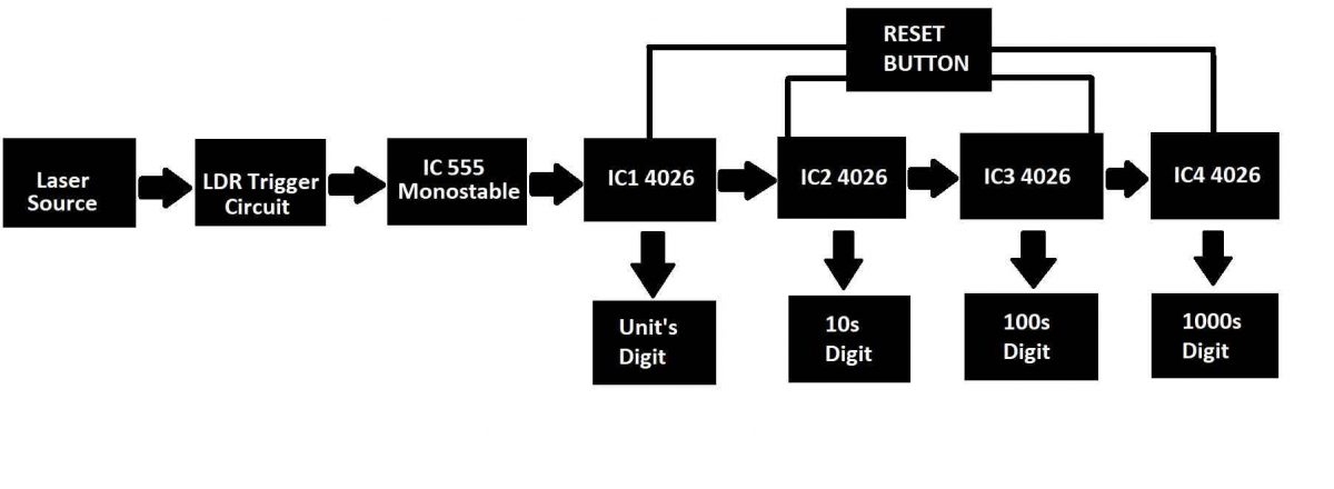
The above image illustrates the block diagram of the proposed visitor counter project. Let’s try to understand each of the blocks.
- In this project we are utilizing one IC 555 and four IC 4026s along with other active and passive components such as resistors, capacitors, transistors and trim potentiometers.
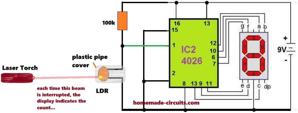
- The first block is a laser source which emits a reasonably bright laser beam which is visible even during day time. We recommend a 5mW laser module which is easily found on e-commerce sites.
- The second block is a trigger circuit which is activated optically. When the laser beam gets interrupted by a person, the circuit generates a negative pulse momentarily.
- The next block is a monostable multivibrator stage which utilizes IC 555 for debouncing the output pulse i.e., the circuit generates a clean clock pulse for IC 4026 counting stage.
- The next 4 blocks consist of four IC 4026s which drives four 7 segment common cathode displays to showcase the number of visitors passed since the circuit turned ON. A reset button is connected to four IC 4026s to reset the display to zero manually.
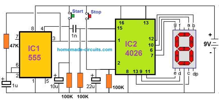
Laser trigger circuit and monostable multivibrator stage:
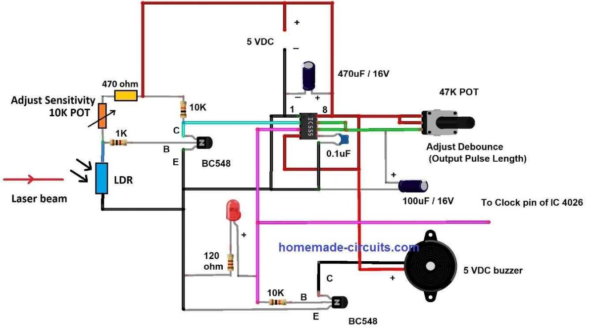
The above circuit consists two circuit stages the laser trigger circuit and the monostable multivibrator. Let’s try to understand the laser trigger stage first.
Laser trigger circuit:
The laser trigger circuit consists of a NPN transistor configured to operate at saturation mode and cut-off i.e., transistor acts like a switch (either fully ON or full OFF).
When the laser beam hits the LDR its resistance drops significantly thus creating a low resistance path for ground signal to enter via base terminal of the transistor.
Now the transistor is OFF and no current passes between emitter and collector terminals and since a pull-up resistor is connected at the collector, there will be +Ve signal at pin number 2 of IC 555. A constant +Ve signal will not trigger the IC 555.
When the laser beam gets interrupted by a person the LDR’s resistance increases significantly, almost like an open circuit. Now the +Vcc signal passes through the base of the transistor via the 10K potentiometer (which can be used for adjusting the sensitivity of LDR).
Now, the transistor has turned ON and conducts current from emitter to collector and a negative signal will be available at collector terminal which triggers the IC 555 to output a pulse to the next stage.
The laser beam hits the LDR again and the transistor goes back to the previous state once the person unblocks the laser beam.
Note: The 470-ohm resistor is here to prevent short-circuit when you set the potentiometer to minimum position and when the LDR is at a lower resistance.
Monostable multivibrator:
Debounce: In electrical and electronic terms, debouncing is a circuit that prevents producing irregular signals generated at the instant of mechanical switching and gives out a clean output.
The purpose of the monostable multivibrator in this project is to debounce the input signal from the laser trigger circuit and to provide a clean signal to the next stage.
When a person blocks the laser beam the transistor could produce more than one pulse at the collector terminal due to the jerky moments of a person and when you couple this directly to the next stage (without monostable multivibrator) the circuit will register incorrect counts.
When we utilize a debouncing circuit the output signal stays constant until the person passes the sensor point, basically you are introducing a delay to the circuit after the detection.
The debouncing length can be adjusted using the provided potentiometer from 0 to 5 seconds. We recommend you to set one second as debouncing delay. A LED and 5V DC buzzer is employed to indicate a person has interrupted the laser and a count has been registered.
The length of LED and buzzer duration depends on debouncing length that you have set, so until the buzzer deactivates no new count will be registered on the machine.
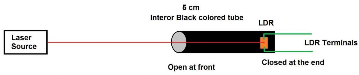
How to mount the LDR and laser setup:
Counter circuit:
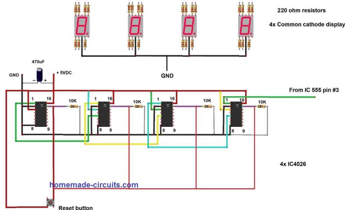
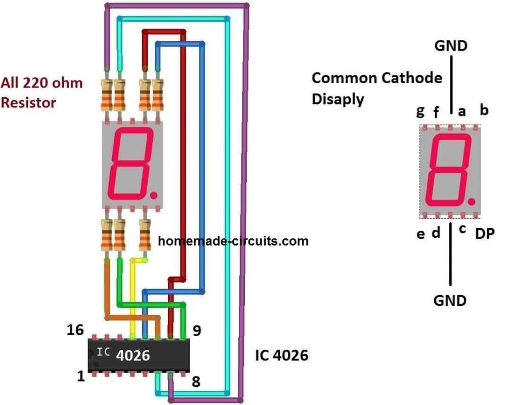
Note: Display connections are not shown in the first diagram for drawing convenience. The second diagram above shows how the displays can be configured to individual 4026 ICs through 220-ohm current limiting resistors.
This proposed stage is responsible for counting the number of visitors and also driving the 7 segment displays. Before we dive into the explanation of the above circuit, it is important to know about the pin diagram of IC 4026 and what each of the pin does, at the same time you will also understand the above circuit stage.
Pin diagram of IC 4026:
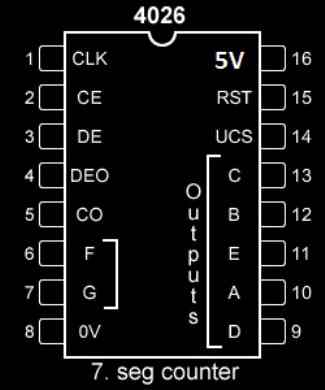
- Pin 1: Clock input, receives clock signal from an external source.
- Pin 2: Clock inhibit, when this pin is connected to +Vcc, the IC ignores the clock input, when this pin is connected to GND, IC accepts input clock pulses.
- Pin 3: Display enable / disable pin. When this pin is connected to +Vcc the 7 segment pins are enabled (A to G) and when connect to GND display pins are disabled.
- Pin 5: This pin performs divided by 10 operation or carry-out. This pin turns high for every 10th input pulse. This is used for cascading multiple IC 4026s to work with 2 or more digits.
- Pins 6, 7, 9, 10, 11, 12,13 are output pins for common cathode 7 segment display (A to G).
- Pins 16 and 8 are +Vcc and GND respectively.
- Pin 15: Reset, when this pin is turned high the count resets to zero, during normal operation this pin must be grounded.
Circuit explanation:
Cascading IC 4026s is done by connecting the clock input pin number 1 of one IC 4026 to pin number 5 of another IC 4026.
The right most IC 4026 will receive the clock signal when a person interrupts the laser beam. When the laser beam gets interrupted 10 times (when the IC receives 10 clock pulses), the right most IC gives out a pulse to next IC (left hand side) and it will display 1 and the right most IC turns zero, now the display will show 0010 (for 10 people), similar process takes place for next two IC stages at higher counts.
A 470uF capacitor is connected to suppress switching noise that could occur while turning ON the circuit. A reset button is provided to reset the display to zero (0000) and also can used to clear any “garbage value” that may appear on the display at the instant of switching ON.
The reset pins of all IC 4026s are connected to ground via 10K resistors, this is because during the normal operation the pin 15 must stay LOW and when you press the reset button the reset pins must go HIGH. If the 10K resistors are absent, it could make a short-circuit.
Simulation:
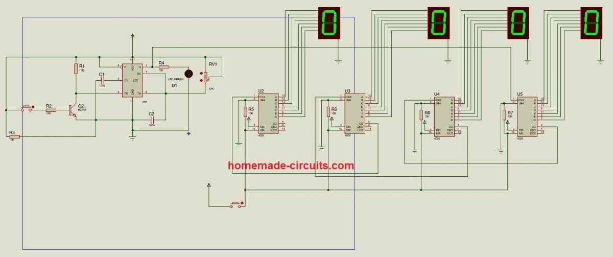
We developed a simulation using proteus software of the proposed project. You can download the given file and test the project on your computer.
When you press the button (on the left-hand side at the base terminal of the transistor) it emulates laser beam interruption and increments a count on the display. A potentiometer connected to IC 555 can be adjusted for testing debouncing delay. The reset button is provided at the bottom of the circuit to reset the displays to zero.


Questions & Answers
Hi Swagatam, I’m a student building a bidirectional version of your visitor counter (IC 555 + IC 4026) — using two LDRs to count up on entry and down on exit, plus a buzzer/LED alarm when the count hits a set limit (like a room capacity warning). Three quick questions:
1. Is comparing which LDR triggers first a reliable way to detect direction?
2. Did daylight ever cause false triggers in your design?
3. What’s a simple way to trigger an alarm once the counter reaches a specific number (e.g., 20)?
Thanks for the great circuit really helped our project!
Hi Sochan, thanks for selecting this circuit for your project, here are the answers to your questions:
Using LDR is fairly reliable way to detect interruptions, provided no ambient light is able to reach the LDR.
Yes, daylight will affect the LDR working, that is why we need to encapsulate the LDRs inside an opaque pipe, open only on one side for the laser beam to enter.
The best way to trigger an alarm after 20 counts is to use a couple of 4017 ICs to count the triggers from the 555 monostable output and when it reaches the specific output of the 40117, drive a transistor based alarm circuit.
I want a visitors counter circuit diagram with single 4026 ,single 555 and it sensor circuit for iti students ,will you please help me sir.And also how to get all these componets.
Hello Suresh,
Please build the following the diagram and check whether the display is showing the counting for the 555 oscillations….if it does then the circuit is working correctly, and now we can replace the 555 section with a sensor for enabling counting of visitors, or objects…please let me how it goes..
yes sir, it is working properly.How to replace 555 with sensor?
ok, then you can try the following modified design:
Can a single 4026 be employed to count from 1 to 9
Yes, as shown in this diagram:

Mr. Swagatam says sir thanks a lot your published article. are available your site counter 7 segment display circuit .
Thank you Zafar, for more counter circuits, you can refer to the following link:
https://www.homemade-circuits.com/?s=counter
I would like to do something like this but need to account for 2 double doors and three single doors, as well as in and out traffic. Could you show accurate info on this? And would this be able to identify moms holding infants?
you can install one on each door and get separate readings. Sorry it cannot differentiate between a single human and a human with an infant