An FM transmitter circuit is a high frequency wireless device which is able to transmit voice signals into atmosphere so that it can be received by a corresponding FM receiver circuit for reproducing the voice signals in a loudspeaker.
Here we’ll discuss how to build small FM transmitter circuits using 10 different methods, one that consists of wire link from the transmitter to the receiver, and the other which is completely wireless and can be used to eavesdrop a particular conversation over a range of about 30 meters, over an ordinary FM radio.
All the FM transmitter circuits presented below are significantly powerful, hard to trace in their hidden positions, and equipped for grasping even the weakest of whispers in the vicinity. Moreover, some of the designs are capable of transmitting the picked information upto radial distances exceeding 500 meters.
The above extraordinary capabilities have forced the legal authorities to enforce stringent laws against the use of these transmitters without permission, so before you make and use one of these make sure you have all the legal formalities completed.
Interested to learn how to detect these hidden Spy transmitters? The details can be found in this bug detector article.
Wireless Design:
I will begin with a transmitter which I have actually built numerous number of times and tested it thoroughly. Subsequently I am going to discuss more such designs which were selected from other websites online.
The sent signals can be received over any standard FM radio, tuned accurately to the respective frequency.
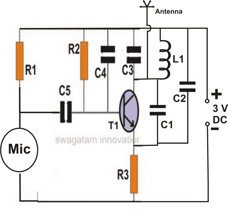
The above shown wireless FM transmitter circuit is basically a small RF transmitter built around a single transistor.
The circuit functions quite like a Colpitts oscillator incorporating a tank circuit for the generation of the required oscillations.
The frequency mainly depends on the positioning and the values of the inductor, C1, C2 and C3. The coil turn distance and diameter may be manipulated a little for optimizing best response over the FM receiver.
A small antenna in the form of a 3 inches wire may be attached at the shown point for making the “bug” highly responsive and generate distortion free signals.
Circuit Diagram
Parts List
- R1 = 3k3,
- R2 = 100K,
- R3 = 470 Ohms
- C1 = 10 pF,C2 = 27 pF
- C3 = 27pF,
- C4 = 102 disc
- C5 = 10uF/10V,
- Mic = condenser mic
- T1 = BC547
- L1 = 3 to 4 turns of 22SWG super enamel copper wire, 5 to 7 mm diameter, air corePlease refer the scanned image of the prototype for getting an idea regarding the coil dimensions.
Now let's discuss a few FM transmitter circuits which can be built using different configurations and features.
One Transistor Design
You might have already come across a host of these extremely basic one transistor FM transmitter circuits, however these may incorporate certain drawbacks as mentioned below:
- No substantial transmitting range.
- No enhanced sensitivity range
- Use 1.5V for operating which render limited capabilities.
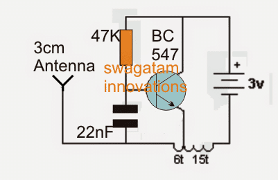
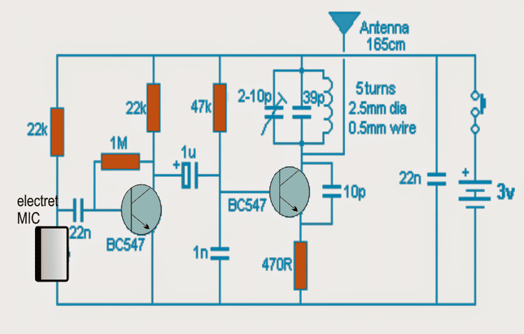
Among the first in the line, which is probably the simplest is shown in the following circuit diagram.
Surprisingly it does not employ a MIC, rather the antenna coil itself performs a dual function of detecting sound vibrations and also transmitting it into the atmosphere.
The design is void of a frequency determining stage and thus does not come under tuned transmitter circuits (we’ll discuss about these later on in the article).
Circuit Operation
The following single transistor FM spy circuit may be understood as follows:
When switched ON, the capacitor 22n inhibits the transistor from switching until it gets charged. A soon as this happens the transistor switches ON via the 47k resistor forcing the pulse through the inductor which feeds back a negative pulse to the base of the transistor discharging the 22n capacitor.
This switches OFF the transistor until 22n yet again charges fully. The procedures take place rapidly generating a frequency across the coil which is transmitted as carrier waves through the connected antenna.
In the course if the coil is subjected to an external vibrational pulse, it’s forced to mount the above explained carrier waves in the air and could be received and retrieved over a standard FM radio positioned and tuned at the same frequency nearby.
The circuit may be expected to work at around 90MHz frequency band.
Calculations
In the above design, a BC547 BJT is used, collector is connected to +3V, emitter is connected to the tapping taken after 6 turn of an air core inductor. The end of the inductor from 6 turn end is connected to the antenna, the other end of the inductor is taken after 15 turns which goes to the -3V. A 4.7k resistor is connected between the base and +3V supply, and a 22nF capacitor is connected between the base of the BJT and the antenna.
Base Biasing (Using the 4.7kΩ Resistor)
The base of the BC547 is biased using a resistor network. The resistor RB = 4.7kΩ is connected between the base and the +3V supply. This sets the base voltage (VB) and thus determines the emitter current.
Since the BJT is in active mode, then the base-emitter voltage (VBE) is typically around 0.7V (for a silicon transistor like the BC547).
Therefore the emitter voltage VE can be calculated as:
VE = VB - VBE = 3V - 0.7V = 2.3V
So the emitter voltage is 2.3V relative to the ground (or -3V, depending on the reference point used).
Inductor and Tank Circuit Calculation
The air-core inductor when combined with the 22nF capacitor in the circuit becomes a resonant LC circuit. We can calculate the frequency of oscillation for this tank circuit using the following formula:
fosc = 1 / (2π√(L * C))
Where:
- fosc = 100 MHz = 100 * 106 Hz
- L = 0.8 µH (chosen value)
- C = 22nF (capacitor value)
In order to calculate the L, we need to estimate it based on the 6-turn and 15-turn arrangement of the coil. However for simplicity we can assume an inductance value L = 10 µH (a reasonable estimate for a 6-turn coil).
Now we can substitute the values into the formula:
L = 10 µH = 10 * 10-6 H
C = 22 nF = 22 * 10-9 F
fosc = 1 / (2π√(10 * 10-6 * 22 * 10-9))
Step-by-step calculation:
Calculate the product of L and C:
(10 * 10-6) * (22 * 10-9) = 220 * 10-15 H * F
Take the square root:
√(220 * 10-15) = 14.83 * 10-6
Calculate the resonant frequency:
fosc = 1 / (2π * 14.83 * 10-6) = 10.7 MHz
Antenna Frequency Response
The frequency of the transmitter (approximately 10.7 MHz) is primarily determined by the LC tank circuit (inductor and capacitor). The antenna should be compatible with this frequency and efficiently radiate the signal.
For getting an efficient transmission, the antennas resonant frequency should ideally be close to the transmitter frequency (around 10.7 MHz). A half-wave dipole antenna for 10.7 MHz would be approximately:
Lantenna = c / 2 * fosc
Where c is the speed of light (3 × 10⁸ m/s) and fosc = 10.7 * 106 Hz.
Lantenna = 3 × 10⁸ / (2 * 10.7 * 106) = 14 m
So the antenna length would need to be around 14 meters for optimal performance at 10.7 MHz.
Modulation with the 22nF Capacitor
For frequency modulation (FM) a 22nF capacitor placed between the antenna and the BJT base is usually utilized. The base voltage can be changed by the input signal such as an audio modulating signal which will modulate the oscillator circuit's frequency. The frequency deviation is determined by the capacitance fluctuation that the capacitor is capable of producing.
In basic FM modulation the frequency deviation from the center frequency is determined by the signal power and the value of the capacitor. In actual use, the divergence may be negligible (a few kHz or MHz), contingent upon the modulation depth and audio signal volume.
Using Tuned Circuit
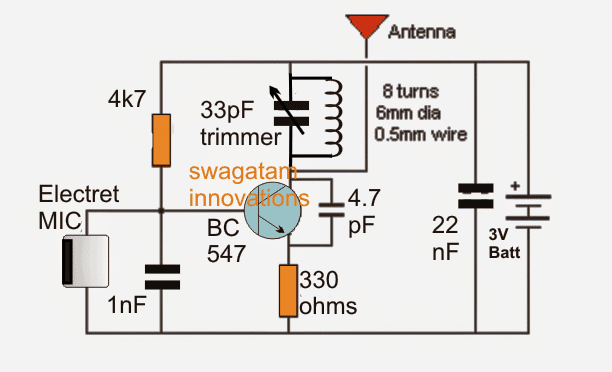
The second example below shows another single transistor FM spy circuit that incorporates a tuned circuit or a frequency determining stage in it.
In the original prototype the coil was created by etching a spiral track layout on the PCB itself, however for optimal gain and performance such etched antenna coil must be avoided and the traditional wire wound type of coil must be employed.
Incorporating Q Factor
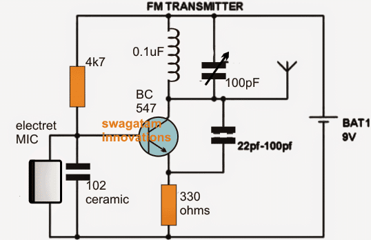
Below's another circuit you would like to know about. The circuit basically makes use of the “Q factor” of the tank network achieved from the coil and the capacitor for generating a relatively high voltage. This stepped up potential attributes the circuit with a rather longer range of transmission.
For an improved performance make sure the coil and the capacitor are positioned as close as possible. Insert the coil leads as deep down the PCB as possible in order to make it tightly hugging the PCB. C2 value could be tweaked for achieving even better response from the circuit.
Preferably a 10pF could be tried. The coil is made of 5 turns of 1mm thick super enamelled copper wire, with 7mm diameter.
Better Saturation Capability
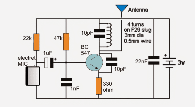
The next FM transmitter design is a bit different than the above types. Fundamentally the design could be classified as a common emitter type, unlike the others which are rather common base types with their design.
The circuit employs an inductor at its base which adds a better saturation capability to the device which in turn allows the transistor to respond in a much healthier way.
Adjustable Coil Slug
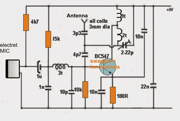
The next design in the list is much superior to its previous counterparts since it uses a slug based variable inductor.
This enables the transmitter to be tuned by adjusting the slug core using a screwdriver. In this configuration we can see the coil being attached to the collector of the transistor which allows a massive 200 meters range to the design, with a current that may be not more than 5mA.
The MIC stage is isolated from the base with the help of a 1u capacitor and the gain of the mic could be well tweaked by adjusting the series 22k resistor.
This circuit could be rated as the best as far range is concerned however it may lack stability which could be improved, we’ll learn how in the following explanation.
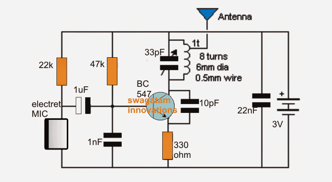
Improved Stability
The stability of the above circuit could be improved by tapping the antenna from one top turn of the coil as shown in the following figure.
This actually enhances the response of the circuits due to a couple of reasons. The antenna gets aloof from the collector of the transistor allowing it to function freely without unnecessary loading, and the slipping of the antenna to the top further allows the relevant side of the coil to get a higher stepped up voltage induced across itself and also the coil generating a higher concentration of transmission power on the antenna.
Although this enhancement may not actual increase the range of the device, it makes sure that the circuit does not get rattled when hand held, or when the grip is encircled close over the circuit inside its enclosure.
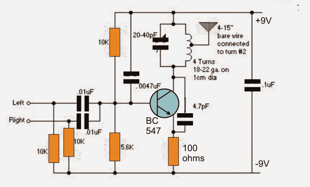
Transmitting Music
If you want your tiny FM transmitter circuit to transmit music instead of spying or eavesdropping, you would probably find the following design interesting.
The proposed FM transmitter will allow combining a stereo input simultaneously from the source so that the info contained inside both the channels get into the air for an optimal reception.
The design configuration is quite identical to the one that’s discussed above so does not need much of an explanation.
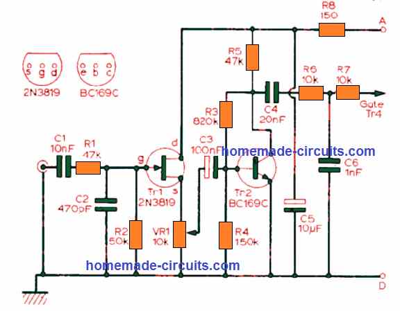
Analyzing a Two Transistor Spy Circuit
Adding a transistor stage to the above discussed single transistor FM transmitters could enable the designs with extreme sensitivity.
An electret MIC itself has a built in FET which makes it very efficient and makes it a stand alone vibration amplifier device. Adding another transistor stage with it enhances the sensitivity of the device to overwhelming limits.
As may be witnessed in the following diagram, the involvement of an extra transistor stage adds up to the gain of the MIC making the entire unit highly sensitive such that it now picks even the sound as low as a pin dropping on the floor .
The extra transistor prevents excessive loading of the MIC thereby ensuring better efficiency to the sensitivity.
Five things that that make the circuit extremely good with it reception are:
- The use of a fix capacitor in the tank circuit along with a adjustable trimmer.
- A low value coupling capacitor with the MIC sufficient to handle the capacitive reactance of the MIC which may be around 4k at 3kHz.
- A 1u coupler is included between the oscillator and the audio amplifier in order to make up for the low impedance rendered by the 47k base resistor.
- The coil used is wound practically using super enameled copper wire which ensures higher efficiency than PCB etched type of coil.
- The entire circuit could be compactly constructed over a small sized PCB for acquiring better stability and a drift free frequency response.
IC 741 Transmitter Using Wire Connection
In the above section we earned about wireless FM transmitter, if you are also interested to know how to make wired transmitter, in which voice could be transmitted through wires into a loudspeaker, then the following design may help
The IC 741 if configured as a non inverting amplifier which performs the function of a pre-amplifier stage.
The gain of this IC 741 preamplifier stage may be varied as desired, using the pot across its input and output pin outs.
The gain setting is used to set the sensitivity of the amplifier and is set to maximum so that even low volume speech conversation may be picked through it.
The mic at the input transforms sound vibrations into minute electrical pulses, which is further amplified by the IC 741 to suitable levels before applying it to the output amplifier stage consisting of a standard push-pull stage. This push pull stage is made using a couple of high gain transistors 187/ 188.
Here, the signal received from the 741 output is suitably amplified so that it finally becomes audible over the speaker.
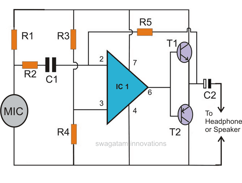
For the 741 circuit, the speaker is only positioned and used as the receiver and may be placed in some other room, where the eavesdropping may be intended to be carried out.
The linking of the speaker from the amplifier circuit may be done through wire connections, preferably by using thin wires and escorting the entire length up to the speaker in some hidden way, probably by laying it under the carpet or across the corners of the room.
For the wireless spy transmitter circuit everything becomes pretty simple and you just have to hide the transmitter circuit in some suitable place, like under the table, couch, sofa etc.
Parts List
- R1 = 10K,
- R2 = 10k,
- R3, R4 = 27K,
- R5 = 1.5 M,
- C1 = 104,
- C2 = 220uF/25V,
- T1 = 188,
- T2 = 187,
- MIC = electret mic,
- IC1 = 741,Power = 9 volt battery
- Headphone = 64 Ohms, or a small speaker of 8 Ohms, 2 inches
Morse Code Transmitter
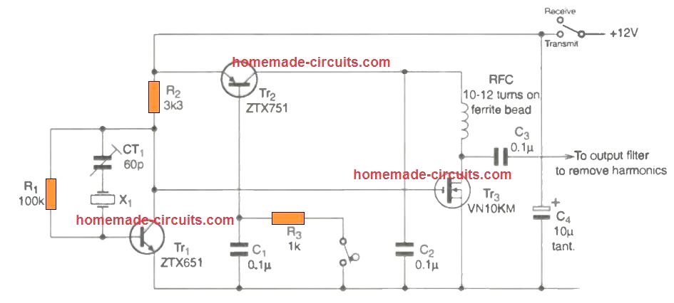
This morse transmitter circuit can be used for transmitting morse codes by tapping the switch associated with R3.
The transmitter will be able to send the signal thousands of miles away which could be received by all VHF, UHF band receivers over a suitable station.
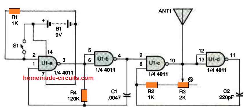
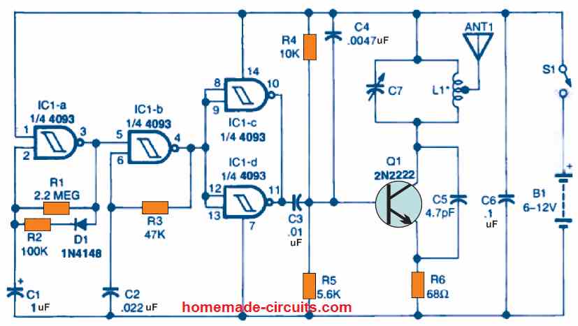
CMOS IC Transmitter Circuit
The project is a straightforward AM/FM transmitter using a single CMOS IC 4011, which could be used to broadcast audio into your AM or FM Radio, TV set, CB radio, police scanner, ham radio, or whatever nearby gadget that is able to catch and reproduce radio waves. The unit will not cause disturbance on your neighbor receiving units, since the Transmitter range is just enough to be restricted to an average-size room, but as long as nobody is standing between the transmitter and the receiver.
Circuit Description
The circuit diagram for the CMOS Transmitter can be seen in the following figure. Power to the circuit is derived via B1, which is a 9 volt battery. A pair of 4011 NAND gate stages, U1c and U1d, are configured like a radio-frequency (RF) oscillator (carrier). The remaining a couple of CMOS gates, U1a and U1b, are utilized to build an audio frequency (AF) oscillator (modulator).
Switch S1 helps activating an deactivating the modulation process to enable the exchange of an complex information with the Transmitter. Once the switch S1 is pressed, the AF oscillator using U1a, U1b, R4, and C1, begins producing an acoustic signal. This signal switches ON and OFF the CMOS gates U1c, U1d, R2, R3, and C2. included in the the RF oscillator stages.
During the ON periods, the RF oscillator operates at 1 MHz frequency. This frequency output is delivered out to the ANT1 as an AM signal.
In the switched ON position, the RF oscillator operates at 1 MHz. The frequeny output is delivered to ANT1 in the form of AM signal. Remember that apart from R3, the AF and RF circuits are organized exactly in an identical manner. The function of R3 is to cause tuning to the Rf oscillator.
As soon as the momentary-contact, pushbutton S1 is pressed and released, the AF oscillator is switched off. Resistor R1 causes the voltage at pin 2 of UIa to become low deactivating the circuit. When you press S1 again, pin 2 turns high. This allows the circuit to yet again begin flicking across its a couple of stable states.
The first of these states is the condition where the U1a output remains high and the U1b output is rendered low. The second state is that condition where the U1a output turns low and the U1b output turns high.
The function of capacitor C1 in this CMOS transmitter circuit is to regulate the speed at which the changeover happens between the two states. If the capacitor hadn't been used, would have caused the circuit to oscillate at an abnormal, and incredibly fast rate. This would have also caused the frequency to get unstable due to varying room temperature, the wire dimensions that join the circuit with each other, and even with the proximity of your body part to the IC.
This is exactly how C1 handles the frequency of the flipping states: As soon as U1a flips and attempts to switch the circuit through the 1st state to the second state, C1 holds the circuit within the first state for a short time, by doing so helps to reduce the frequency. The capacitor is able to do this since it is coupled to the input of U1a, in the same way as R4 is.
So long as C1 is in the charged up condition, it is able to "overpower" resistor R4, stopping it from modifying the U1a input. Now, as C1 begins losing charge by means of R4, this permits U1a to topple over to the second state.
More Transmitter Circuits
The transmitter coil L1 for all the following circuits are created by hand winding 4 turns of 18 to 22 SWG super enameled copper wire over a 1 cm air cored former, using card board or plastic for the former material. The number of turns of L1 can be manually adjusted so that FM transmitter circuits are able to transmit signals within the high VHF range using 2 or 3 turns for L1, or across the lower VHF range of 50 to 80 MHz using 5 to 7 turns for L1.
The variable capacitor connected parallel to the coil L1 in the all the following circuits can be a 33 pF trimmer or any FM gang capacitor.
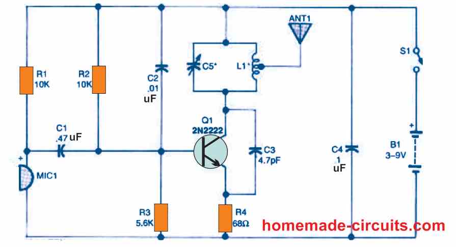
150 Feet Range Transmitter
The below shown One-Transistor FM Transmitter circuit's output, which can be received by any FM receiver within approximately 150 feet or less of the transmitter, provides great functionality and is suitable for wireless mic usage.
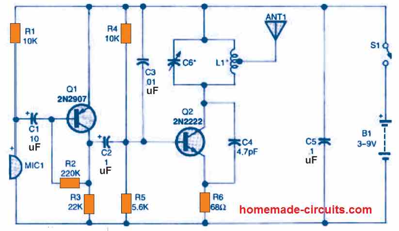
100 meter Range Transmitter
The next Two-Transistor FM Transmitter is essentially similar to the preceding design, with the exception of an additional transistor and a pair of resistor/capacitor values that have been changed to match the new circuit layout. The range of this transmitter is around 100 meters.
Example Calculation for a 100 MHz FM Transmitter:
Resonant Frequency Formula:
The frequency of oscillation for the LC tank circuit is:
fosc = 1 / (2π√(L * Ceq))
Where:
fosc = 100 MHz = 100 × 106 Hz
L = 0.8 µH (chosen value)
Ceq = Equivalent capacitance of the capacitors in the tank circuit (which is to be calculated)
Calculating Equivalent Capacitance (Ceq):
We can rearrange the formula to solve for Ceq:
Ceq = 1 / ((2π * fosc)2 * L)
Now we substitute the known values:
fosc = 100 × 106 Hz
L = 0.8 × 10⁻⁶ H
Step-by-step calculation:
Calculate 2π * fosc:
2 * 3.1416 * 100 × 106 = 628.318 × 10⁶
Squaring the result:
(628.318 × 10⁶)2 = 3.947 × 10¹⁷
Multiplying by L:
3.947 × 1017 * 0.8 × 10-6 = 3.158 × 10¹¹
Taking the reciprocal to find Ceq:
Ceq = 1 / (3.158 × 10¹¹) = 3.17 * 10-12 F = 31.7 pF
Thus we get Ceq ≈ 31.8 pF.
If we split the Ceq into Two Capacitors (C1 and C2), then:
In a Colpitts oscillator, the Ceq is formed by two capacitors in series. The equivalent capacitance can be calclated using the following formula:
Ceq = (C1 * C2) / (C1 + C2)
Rearranging the formula to solve for the C2:
C2 = (C1 * Ceq) / (C1 - Ceq)
Choosing the C1 and Calculating the C2:
Let us choose C1 = 15 pF (a realistic value).
Substituting the values into the formula:
C1 = 15 pF
Ceq = 31.8 pF
C2 = (15 * 31.8) / (15 - 31.8)
Step-by-step calculation:
Multiplying C1 and Ceq:
15 * 31.8 = 477
Subtracting Ceq from C1:
15 - 31.8 = -16.8
Dividing:
C2 = 477 / -16.8 ≈ 47.1 pF
Final Tank Circuit Values are given below:
C1 = 15 pF
C2 = 47 pF
L = 0.8 µH
The above values produce an equivalent capacitance of approximately 31.8 pF which causes a resonant frequency of 100 MHz.
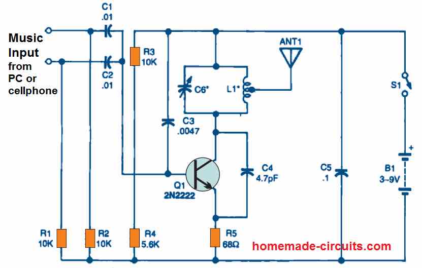
Music Player Transmitter
The next CD player, USB device, and mobile phone The Multimedia Transmitter sends audio signals from your PC, CD player, or smartphone to your FM audio system for playback through the system's loudspeakers without using connecting wires.
Beeper Transmitter
The Beep Transmitter emits a series of intermittent beeping frequency that may be easily received and picked up by any FM radio within its range.


Questions & Answers
As to the second schematic’s inductor I have 2 questions:
1) what is is the diameter and length of the coil, and
2) does the inductor have to be a single continuous winding?
The diameter can be 5mm or 6mm, yes it has to be a single continuous winding….
Good morning Sir
Thanks for the circuits.
Sir I need circuit diagram for an fm transmitter for a community radio.
Range 20km
thanks
Good Morning Ngang,
I think you can try the following concept and see if it works or not:
https://www.homemade-circuits.com/27-mhz-am-fm-transmitter-circuit-for-citizen-band-communication/
thanks Mr swag for this post but I need a little help for my school project is there uwb based transceiver that I can apply for voice communication
You are welcome Nnaji, I think I have a transceiver related circuit in this blog, you can check it through the following link:
https://www.homemade-circuits.com/mini-transceiver-circuit/
You can use USB 5V for the first circuit and check how it works.
thank you sir but I meant uwb ultra wide band
Oh, sorry I misinterpreted it to be USB. In that case, unfortunately i do not have the one you are looking for.
Ratings of the variable capacitance C7 and the inductance L1 of beeper transmitter are not mentioned in the circuit diagram. Also the antenna particulars also not mentioned. Antenna to be tapped from center fo L-1 coil?
Please read the section under “More Transmitter Circuits”.
The antenna can be any flexible wire of 6 inches, or any telescopic type antenna will also work…
Sir instead of 3volt may I use 3.7 volt battery to power the transmitter , will the circuit work
Hi Shantanu, yes, 3.7V battery also work…
sir, what is the risk you mean that I have to face while constructing this transmitter circuit? How to avoid the risk then?
hello sir I love the way u teach is understandable thanks. Pls sir what component cause the ” hisss” sounds in the mic receiver and transmitter
Thank you Joseph, what kind of receiver are you using, is it an FM radio? There should not be any hissing sound at the receiving frequency, it should be totally silent.
Hello L.Amalraj, there are no risks except facing legal issues if personal wireless broadcasting is restricted in your area or country.
Are there no mono audio transmitters (stereo exists, but mono without microphone does not exists)?
The above designs are all mono transmitters.
hey, how can i get the components?
here in Rwanda it’s hard to find all those components but some!
i want to build a two transistor spy circuit, if someone have them DM me
are there circuits for power amplifier?
Sorry help me to know the lines of positive and negative in old mobile phone camera,am confused so much!
What frequency range can we expect for the first wireless design?
Between 70 MHz and 110 MHz
How to tune the frequency for the first wireless design?
You can tune by gently expanding or compressing the L1 coil with your fingers.
Hi,
I have a incumming 433.92 mHz signal and I would like to convert this to a Bluetooth signal, is this possible?
Rgds
Eddy
Hi, there are “Bluetooth converter modules” available in the market which you can investigate, and check if those units can be used for your application or not.
Hey, I wanted to ask if you have a design for a simple AM modulator and demodulator. I am a Communications student and we are doing a project on modulation. I have already got two oscilloscopes built which generate 5khz and 165khz for message and carrier, respectively. I couldn’t find any circuits for AM on your site that’s why I commented here. Thanks in advance!
Hi, I have an article in this blog which discusses a few AM radio circuits, you might find it useful:
https://www.homemade-circuits.com/simplest-am-radio-receiver-with-speaker/
I also have another related article, which you can check it out here:
https://www.homemade-circuits.com/tuned-radio-frequency-receiver-trf-circuits/
Nice program! I am helping a friend whose assignment for school is to construct the 741 transmitter and I am assisting her finding the required parts. Perhaps you can provide me with a little more info regarding the 187 & 188 transistors. I have located a couple of different items with a variety of prefixes to 187, 188 but am not sure what to get. Appreciate any help you can provide!
Michael
Hi, thanks, and glad you liked this post! 188 and 187 transistors are actually the newer versions of the old AC128 and AC127 transistors. If you are unable to find these transistors then you can simply replace them with the modern 2N2222 and 2N2907 transistors, without any issues.
The above mention circuit are good for experimenter or novice who want to explore and learned the FM transmission, hiw about synthesized or crystal controled transmitter for 5- to 30watt community radio service sir ?
Thank you for your feedback! I have a long range transmitter circuit in this blog which can reach upto 5 km, but I am not sure how much wattage it can produce. You can find the link here:
https://www.homemade-circuits.com/long-range-transmitter-circuit-2-to-5/
I assembled and tested the your music player transmitter circuit , i used battery power supply , but when i connectted it my TV AV output, i hear hum noise of power freqnency at the background in my head phone radio reciver, how to eliminate it .
I am glad you could build it successfully. It can be perhaps solved if a 50 Hz hum filter or a notch filter is inserted between the TV AV output and the transmitter input.
You can also try increasing the C5 value to 100uF/25V and check the response.
https://www.homemade-circuits.com/simple-hum-filter-circuit-for-amplifiers/
será que funciona esses circuitos e tem bom rendimento no audio
Yes, they will work with good audio performance.
What is the range of Two Transistor Spy Circuit?
maximum 100 meters
Greetings sir, please sir is it possible to have two antennas on a wireless FM Microphone circuit base on diversity concept?
Thanks for your kind answer.
Hello Charis, as far as I know two antennas cannot be used in any FM transmitter circuit, because that won’t make sense and would be technically inefficient.
Thank you so much for these detailed and useful guidance,sir.
Thanks, and glad you liked it…
Hello sir, may I ask, for the two transistor spy circuit, in order to listen from a specific frequency, is it possible I use a fixed capacitor of my choice in place of the trimmer capacitor so as to transmit my signals at that frequency provided by the fixed capacitor?
Hello Jonathan, yes that is possible. You can use a fixed capacitor in place of the trimmer to transmit signals at a specific frequency.
Hello Swagatam Sir !
I’m trying to make a Wireless Telegraph for my 2nd year project. Which leaves me some questions.
1. Is it possible to make a Transmitter which only transmits signal when key is pressed ON/OFF and Receiver circuit receives signal and turns LED light ON/OFF (Like Morse code) with just basic electronic components and with no IC’s and microcontrollers.
2. As its operating range would be just few 2-3 meters, Is it legal in India to make one.
Hello Yash, yes it is possible.
You can try the concepts presented in the following article:
Simple FM Radio Circuit Using a Single Transistor
A room transmitter is legal all over the world.