The post describes a simple 220V mains transformerless LED candle light circuit which switches ON automatically in the absence of ambient light in the room and vice versa. The idea was requested by Mr. Don
Technical Specifications
I only dabble with electronics here and there but in trying to move from incandescent and CFL's to LED's I have come across a strange dilemma.
I have used electric 110v-120v "Sensor Candles" for many years and they employ a very simple circuit of an LDR/Resistor/Switching Transistor on a circuit board about 1/2" square that fits into the body of the candle.
The candles (not flickering) use c7 5-7 watt incandescent bulbs. The equal c7 LED of about .5 watts do not work in these candles.
What is it about the LED bulbs that causes them not to work? Is there a modification that can be done to the existing circuit boards to make them compatible with LED's?
I have searched all over for electric candles that use LED's and can find none.
The LED candles that are available are only battery operated. It boggles my very old and simple mind that the switching transistor does not simply switch the necessary voltage to the LED.
I find it hard to understand why these products have not been produced to function with LED's. Perhaps this is a product to might want to design for manufacturers.
I have one grandchild who has a degree in electrical and computer engineering that promised to review the possibilities but other his other priorities have taken precedence, even though I told him that a patent on the idea might be rewarding.
I can send you a candle, circuit board, or whatever information you may require.
Thanks,
Don Jengo
The Design
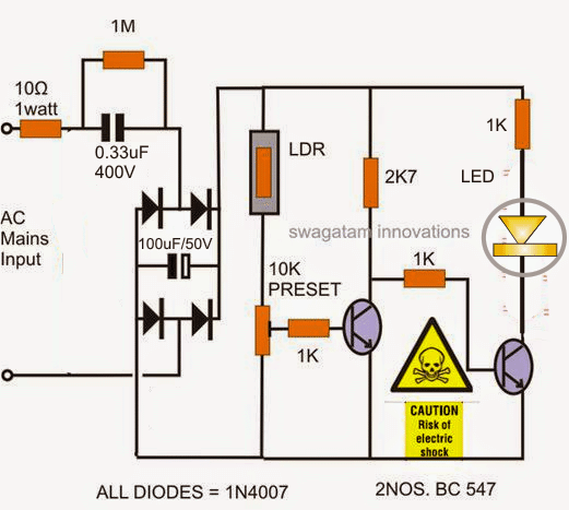
The proposed automatic darkness triggered candle light circuit can be seen in the shown diagram which uses an amber colored LED for simulating a candle light effect.
As per the request the circuit needs to be LDR based which also means the unit must activate only when it's sufficiently dark inside the room or as soon as the main indoor lights are switched OFF, or when the user goes to bed.
The presented automatic LED candle light is very straightforward and fairly reliable with its operations, I have explained it through the following explanation:
The 0.33uF/400 V capacitor along with the four diodes and capacitor forms a compact transformerless power supply circuit stage for powering the LED during dark or in the absence of ambient light.
The first transistor from left in the presence of ambient light conditions receives sufficient base drive via the LDRs lower resistance and conducts to keep the base of the second BC547 at ground potentials.
Due to this the second transistor remains inactive and switched OFF making sure that the connected LED also remains switched OFF under such ambient external illuminations.
However as soon as the ambient light around the LDR diminishes or is switched OFF, the left transistor is inhibited from the base drive due to the LDRs high resistance in the absence of ambient light, which further prompts the right hand side transistor to start conducting, thereby switching ON the LED.
The opposite reaction is quickly exhibited in case the ambient light is switched ON or during daybreak.
Caution: The circuit is not isolated from mains voltage, utmost care and precaution is expected from the user wile assembling, testing, installing the unit in powered situation.
The LDR must be appropriately enclosed inside a suitable cover such that the LED light never reaches it under any condition, otherwise it may lead to false triggering and oscillations of the circuit and the LED.


Questions & Answers
Hi,
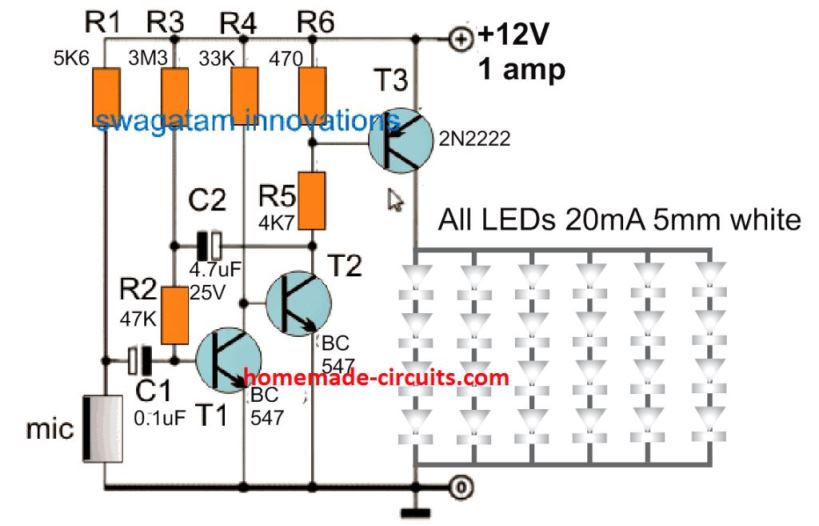
I have had an idea of music driven LEDs wirelessly which seems to be very complex to me. Let me try to make the problem understandable. I want a music activated led driver but without a mic as the audio input to the driver. I want to stream the music to my Bluetooth speakers/headphones meanwhile the LEDs reacting to the music as they would have with the mic. Basically I want to play loud music with the light effects without bothering my neighbors. I know how to build the circuit using Arduino, mic being the source to the driver. I have been looking for a solution to drive it wirelessly as I explained above for months now but I couldn’t get to a solution. I hope I have made you understand the problem, kindly help me to build this project. If you need any clarification please get in touch with me. I hope you find this project exciting and provide me enough input so that I could build it.
Please post your question under the following article, the above article is about LED candle light:
Wireless Music Level Indicator Circuit
Sir I have 12v 8ah battery and 12v dc led bulb and I want to add LDR function please help me with circuit
Gurucharn, you can try one of these concepts:
https://www.homemade-circuits.com/how-to-make-light-activated-day-night/
Hi Swag,
What’s the minimum voltage I can apply to this circuit?
NA
Hi Nelio,
you can use 12V DC without the capacitor. With the capacitor the minimum input should be above 25V AC.
yes can be used
Sir can I use 9v battery for this circuit
And is their any value for LDR sir
a good recommended LdR will normally have a resistance value between 10K to 100K in room light and over 3M in darkness….you can check this while buying with a ohm meter
Sir can I use 12 v battery for this circuit
yes 12V battery or adapter can be used
Dear sir Can I use the 12v relay
yes can be used, but will need to make 0.33uF into 1uF
what is the wattage of the led use and the color
3.3 v, 20 ma, amber or yelllow
Dear sir in my area I can't found 0.33uf/400v & 100uf/50v. If its possible with a few changes please help me out.. I'm very interested about your site. Thank you.
Chiranjit, you can try other closer values between 0.22uF/400V to 0.47uF/400V
same for 100uF/50V…. use any close value, it's not critical