A very simple temperature indicator circuit can be built by interconnecting a single transistor, a diode and a few other passive components.
Using Transistor as a Heat Sensor
As we know that all semiconductors have this "bad habit” of changing its basic characteristics in response to ambient temperature changes.
Especially basic electronic components like transistors and diodes are very much prone to their case temperature variations.
The change with their characteristics with these devices is typically in terms of the passage of voltage through them, which is directly proportional with the magnitude of the temperature difference surrounding them.
Using a Transistor (BJT) as the Temperature Sensor
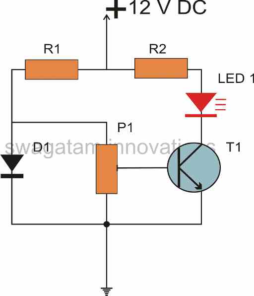
In the present design a diode and a transistor are configured in the form of a bridge network.
As both these active parts have identical properties as far as ambient temperature changes are concerned, they both complement each other.
Using Diode for Creating a Reference Voltage
The diode is place as the reference device while the transistor is connected to perform the function of a temperature sensor.
Obviously since the diode is placed as the reference, it has to be placed in an environment with relatively consistent temperature conditions, otherwise the diode will also start changing its reference level causing error in the indication process.
A LED is used here at the collector of the transistor, which directly interprets the transistor conditions and therefore helps to show how much temperature difference is taking place around the transistor.
LED Indicates the Temperature Change
The LED is used to get a direct indication of the temperature level sensed by the transistor.
In this design the diode is placed at the ambient temperature or at the room temperature which the transistor is placed or attached to the heat source which needs to be measured.
The base emitter voltage of the transistor is effectively compared with the reference voltage level produced by the diode at the junction of D1 and R1.
This voltage level is taken as the reference and the transistor remains switched OF as long as its base emitter voltage remains below this level. Alternatively this level may be varied by the preset P1.
Now as the heat over the transistor starts rising it base emitter starts rising due to the altering characteristic of the transistor.
If the temperature crosses the preset value, the base emitter voltage of the transistor exceeds the limit and the transistor starts conducting.
The LEDs gradually begins to illuminate and its intensity becomes directly proportional to the temperature over the transistor sensor.
Caution
Caution must be maintained, not to exceed the temperature over the transistor above 120 degree Celsius, other wise the device may get burnt and damaged permanently.
The proposed simple temperature indicator circuit can be further modified for making it switch an external appliance ON or OFF in response to the sensed temperature levels.
How to Calculate the Temperature Thresholds
I will discuss it in my forth coming articles. The resistor values of the configuration is calculated using the following formula:
R1 = (Ub - 0.6)/0.005
R2 = (Ub - 1.5)/0.015
Here Ub is the input supply voltage, 0.6 is the forward voltage drop of the BJT, 0.005 is the standard operating current for the BJT.
Similarly, 1.5 is the forward voltage drop for the selected RED LED, 0.015 is the standard current for illuminating the LED optimally.
The calculated results will be in Ohms.
The value of P1 may be anywhere between 150 to 300 Ohms


Questions & Answers
Hello sir I was making a relay switch for my little project but the problem is my power supply is 48v and the load is also 48v 8a but I couldn’t found out the 48v contact rating relay with 5pins can you help me because all the relay rated at 30v 10a maximum I just. Wanna know that can I connect this relay with the 48v load ? The coil voltage is 48v of the relay !
Hello Salim, If the coil voltage of your relay is 48V then you can safely connect it with a 48V supply.
The contacts of a relay is rated with amps not with voltage. So if the contacts are rated at 10 amps then you can connect a 48V 8 amp load with your relay contacts.
Thanks for the information sir so thats means 48v coil voltage relay is super good for the 48v 8a load ! And also I wanna tell you something I have tried another relay 12v coil voltage and 28v 10a contact rating it worked but the issue is I can see some sparks under it when it’s going to turn off !
Salim, if you multiply the I x V of your 48V relay’s contact rating, you get 30 x 10 = 300 watts.
So if you are using 48V load for the contact rating make sure the current doesn’t exceed 300/48 = 6 amps.
So I think 8 amp cannot be used, you must upgrade the relay contact wattage rating.
Sparks are actually normal as long as the rating is selected as per the above explanation.
Please note that you are commenting under the wrong article, so i will have to delete these comments after sometime.
To continue the conversation please comment under an article related to RELAYs.
sir I get 2280 for R1 ,and 700 for R2 respectively.
are the values in kilo ohms or just ohms ,
and can I use _TIP41 For the transistor and IN4007 For the diode? ,am thinking of placing the transistor as close as possible to the heatsink of my amplifier bolting it beside the chip.
Shedies,
The results will be in Ohms.
TIP41 is a power transistor and might not be suitable for this application, same for the 1N4007 diode also.
You can use BC547, 2N2222, 8050 for the transistor, etc. For diode only 1N4148 is recommended for a perfect response.
Please sir, how to make it to automatically on/off an appliances and how to calculate the temperature value. Thanks
you can try this
https://www.homemade-circuits.com/how-to-build-simple-electronic/
Please tell me how can I get heat in the range of 45 deg. to 50 deg.
Can this be used to indicate water temperature? Can a sl100b transistor be used?
yes it can be used for indicating water temp
What is the rating of preset?
Can i connect buzzer@100c
buzzer will not work properly
sir, can i use diode NI5408 for this circuit?
yes you can use it.
Drop me an email pls @ styleang@gmail.com if possible. Thanks sir!
Hi sir, I would like to check with you how can I use temperature circuit to detect the water temperature, if the water temperature is high, the relay will turn on the fan for cooling purposes. Thanks!
yes you can send it through email or upload on any free image hosting site and provide the link to me.
I have a simple circuit from my school textbook and i have made it out. i have a problem now is that i don't know how to set the 2 variable resistor to make the circuit work. i may need to send you the circuit diagram, can i send it thru email to you?