Linear Hall-effect ICs are magnetic sensor devices designed to respond to magnetic fields to produce a proportionate amount of electrical output.
It thus becomes useful for measuring the strength of magnetic fields, and in applications that require an output switched through magnetic triggers.
The modern hall effect ICs are designed with immunity to most mechanical stressful conditions such as vibrations, jerks, shocks and also against moisture and other atmospheric pollutions.
These devices are also immune to ambient temperature variations which otherwise could make these components vulnerable to heat producing incorrect output results.
Typically, modern linear Hall Effect ICs can work optimally over a temperature range of -40 to +150 degree Celsius.
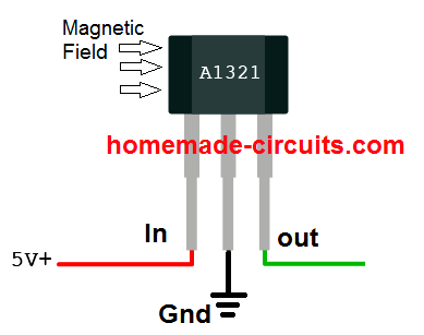
Basic Pinout Diagram
Ratiometric Specified Functioning
Many standard linear Hall-effect ICs such as A3515/16 series from Allegro or DRV5055 from ti.com are “ratiometric” by nature, wherein the devices quiescent output voltage and sensitivity vary in accordance with the supply voltage and ambient temperature.
The quiescent voltage could be typically half the supply voltage. As an example if we consider the supply voltage to the device to be 5V, in the absence of a magnetic field its quiescent output would normally be 2.5V and would vary at a rate of 5mV per Gauss.
In case the supply voltage was to increase to 5.5V, the quiescent voltage would also correspond to 2.75V, with the sensitivity reaching the 5.5mV/gauss.
What is Dynamic Offset
Linear Hall-effect ICs such as the A3515/16 BiCMOS incorporate a proprietary dynamic offset cancellation system with the help of an in-built high frequency pulse so tat the residual offset voltage of the Hall material is controlled appropriately.
The residual offset could arise normally due to over-molding of the device, temperature discrepancies or due to other relevant stressful situations.
The above feature renders these linear devices with a significantly stable quiescent output voltage, well immune to all types of external negative impacts on the device.
Using a Linear Hall-effect IC
The Hall-effect IC may be connected with the help of the given connections, where the supply pins must go to the respective DC voltage terminals (regulated).The output terminals may be connected to an appropriately calibrated voltmeter having a sensitivity matching the Hall output range.
Connecting a 0.1uF bypass capacitor directly across the ICs supply pins is recommended in order to safeguard the device from externally induced electrical noise or stray frequencies.
After powering up, the device may require a few minutes of stabilization period during which it must not be operated with a magnetic field.
Once the device gets internally temperature-stabilized, it may be brought under the influence of a external magnetic field.
The voltmeter should immediately register a deflection corresponding to the strength of the magnetic field.
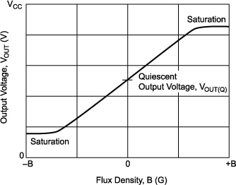
Identifying Flux Density
For identifying the flux density of the magnetic field, the devices output voltage may be plotted and located over the Y-axis of a calibration curve, the intersection of the output level with the calibration curve would confirm the corresponding flux density on the X-axis curve.
Linear Hall Effect Application Areas
- Linear Hall-effect Devices could have diverse application areas, a few of them are presented below:
- Non-Contact Current sensing meters for sensing current externally passing through a conductor.
- Power sensing meter, identical to the above (watt-hour metering) Current trip-point detection, where an external circuitry is integrated with a current sensing stage for monitoring and tripping a specified over current limit.
- Strain gauge meters, where the strain factor is magnetically coupled with the Hall sensor for providing the intended outputs.
- Biased (magnetically) sensing applications Ferrous metal detectors, where the Hall effect device is configured to detect the ferrous material through relative magnetic induction strength detection Proximity sensing, same as the above application, the proximity is sensed by approximating the relative magnetic strength over the Hall device.
- Joy-stick with intermediate position sensing Liquid-level sensing, another relevant sensing application of the Hall device. Other similar application which involve magnetic field strength as the main medium along with the Hall effect device are: Temperature/pressure/vacuum sensing(with bellows assembly) Throttle or air valve position sensing Non-contact potentiometers.
Circuit Diagram using Hall Effect Sensor
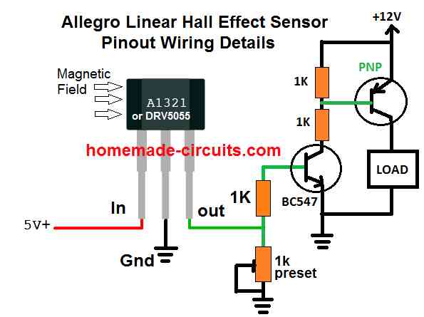
The hall effect sensor explained above can be quickly configured through a few external parts for converting magnetic field into electrical toggling pulses for controlling a load. The simple circuit diagram can be seen below:
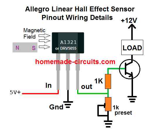
In this configuration, the hall effect sensor will convert a magnetic field within a specified proximity and will convert it into a linear analogue signal across its "out" pin.
This analogue signal can be easily used for driving a load or for feeding any desired switching circuit.
How to Increase Sensitivity
The sensitivity of the above basic hall effect circuit could be increased by adding an additional PNP transistor, with the existing NPN, as shown below:
Using Opamp
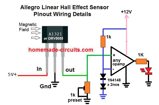
The DRV5055 hall effect sensor can be also integrated with an operational amplifier for getting the switch ON results in response to a magnetic proximity with the hall effect device.
Here the inverting input of the op amp is set to fixed reference of 1.2 V using two series 1N4148 diodes, while the non-inverting input of the op amp is configured with the output of the hall effect for the intended detection.
The 1k preset is used for setting up the switching threshold at which the op amp is supposed to switch, depending on the strength and the proximity level of the magnetic filed around the hall effect.
In the absence of a magnetic field, the hall effect sensor output remains below the set threshold of the op amp inputs.
As soon as the output from the hall effect goes above the non-inverting threshold of the op amp, as set by the preset and the reference level of the inverting input, the output of the op amp turn high, causing the LED to switch ON. The LED could be replaced by another circuit stage for a switching ON some other desired load.


Questions & Answers
Can SS49E linear hall effect sensor be used in place of A1321 in your above circuit for increasing sensitivity?
Yes the SS49E can be used instead of the A1321, because both are linear hall effect sensors and their output voltage changes linearly with magnetic field strength.
But Sensitivity will NOT really increase by using SS49E compared to A132 because Both SS49E and A1321 have similar sensitivity ranges around 1.4 mV/Gauss to 2.5 mV/Gauss.
дякую за працю.
продовжуй
Great site!
You are an excellent teacher. Creative and patient.
Thanks for all the shared knowledge.
Thanks, I appreciate your kind feedback.
Hi Swagatam,
I want to control the brightness of a 3W power LED using a hall effect sensor. The circuit will work with a 3.7 v Li-Ion battery. The LED current will vary between 600mA-1A. When the magnet approaches the sensor, the brightness of the LED will increase, and when it moves away it will decrease. I would be very happy if you could help me design this circuit.
It works well.
Hi Ibrahim,

I think you can try the following circuit diagram, with some modifications:
Remove the load (LED) from the collector side and put it between the emitter and ground of the transistor.
For the transistor use TIP122.
The 1K preset may not be needed, you can remove it.
Let me know if you any more doubts.
How do I find the part number of a Hall Effect Sensor with TO-92 case 0V out at zero mag field, 2.5V out at 50% mag field, 5V out at full mag field ? Similar to 49E series. I do not know how to find the part number and there are 30,000 data sheets to look through.
I understand your problem, however the challenge is as difficult for me too. I am too having difficulty figuring out the exact part number, I may have to scan many datasheets which I find quite difficult.
Hello, I have a solar DC coupled inverter and battery – myenergi only uses AC CTs but I would like to trick the system by matching the outputs. i.e. if there is 2kW of power being sent from the solar to the battery what is the output of the hall effect sensor (is this measured in 0-5volt?) for the sam amount of power in an AC circuit what is the output of the CT (is this measured in 4-20mA) is ther a way to convert the hall effect to output to match the equivelent AC CT output. therefor the system will see the amount of power – I also need to know if this can be directional (dual sensor?)
Sorry Mark, I can’t figure it out, looks difficult to understand and solve.
Reversible Turns Counter
I have a (approximately) 25 turn roller inductor in my antenna matching device. The inductor is adjusted my turning a hand knob on its 1/4 inch shaft to obtain the desired impedance. My intent is create a digital readout of turns (1/2 turns actually using 2 narrow tape magnet strips) that will decrease count when the knob is turned in reverse.
I know I need a dual-hall sensor (looking at TI TMAG5111) and wish to combine it with my obtained Digiten GDD7949AT-P24V-BU counter, which is a PCB attached to a nice 4 segment display. The PCB has 2 directional contacts: one for incrementing the count up (BROWN) and another for decrementing the count down (BLUE wire).
I’m not an engineer, so I need recommendations on
* the dual-hall sensor
* small breadboard to mount the sensor and bolt to chassis
* a switching circuit from OUT2 of the sensor to utilize either BROWN or BLUE wire to connect to OUT1 of the sensor
Would you please help me with this?
Sorry, I could not understand your application, so it is difficult for me to answer your questions.
This is great information for a problem I’m having with a Harley Davidson motorcycle throttle. The throttle actually uses two hall effect sensors. One circuit is setup to provide a 0-5V signal increasing in voltage and the other provides a 5-0V signal decreasing (as the throttle is turned). They sum the outputs and check that they are about 5V as a safety to prevent runaway acceleration.
On my motorcycle I can measure the 5-0V decreasing signal but I cannot get a value from the output of the 2nd sensor. My guess is that the output circuit is “open” between the sensor and the Electronic Control Module (broken wire, bad connector, failed ECM module). Do you agree that I’m in the correct direction.
thank you
I agree, your assumption may be correct, however it can be verified only after a practical checking.
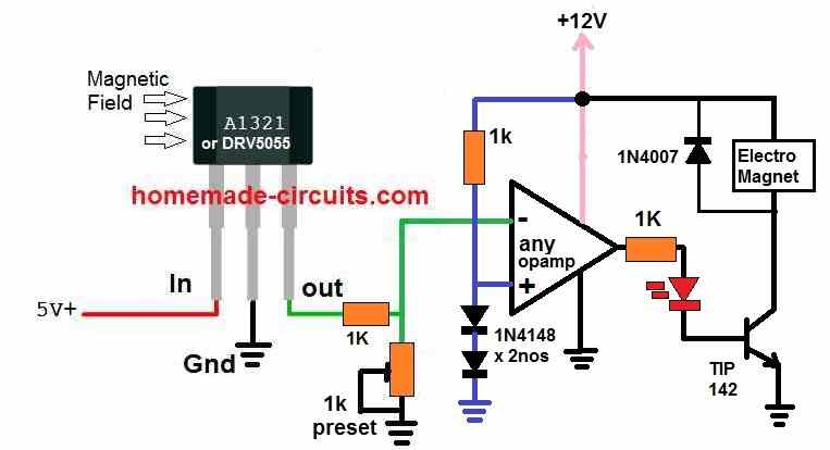
Hi Could you help me design a hall effect circuit board capable of powering an attractive electromagtic holding a 40-50lb load?
Hi, can you please explain the role of the hall effect sensor, how it would be implemented to function.
Thanks for your reply! I want to use the hall sensor to hold a 40-50 lb weight, attached to a permanent magnet in levitation below the electromagnet. Plan to use a permanent electromagnet that uses current to neutralize the magnetic field instead of create it.
OK, you can try the following design:
Interesting information. Regards and Good luck
Thank you!
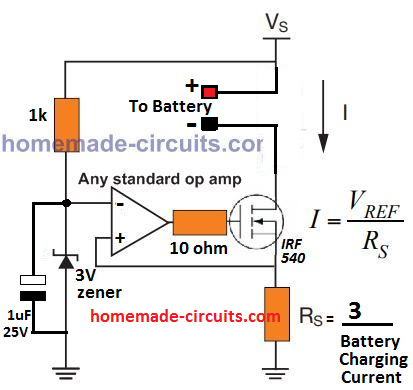
Can I use the last circuit which has opamp to sense overload current to switch off inverter during overload condition? If possible, how can I connect it to sense the overload? Thanks
You can try the following circuit instead. Replace the “battery” with your inverter and connect Vs with your battery positive:
Good morning Sir. Thanks for your response. I have some questions and observation.
[1] Should I Connect drain of irf540 to inverter negative and battery negative terminal to ground of the circuit?
[2] is this correct for 1000w inverter, to get shunt for the referred circuit?
P=IV
700w=I×12v
I=58.33A
Then R=3/58.33, R=0.05ohm
That is 1/R=(1/r1)+(1/r2)
I/R= 1/0.1+ 1/0.1
R=0.05ohms when using two 0.1ohm in parrallel.
[3] will the circuit function for 24v or 48v input inverter?
[4] In case for higher power like 5kw, will I change any components apart from the shunt resistor and addition of voltage regulator to protect the IC?
[5] I studied the circuit and is like the overload shutdown will be fluctuating like ‘on’ ‘off’ ‘on’ ‘off’……. Until the heavy load is removed. It will not shutdown permanently like SCR as in the case of low battery shutdown.
Hi Emmanuel,
Your [1] and [2] points are correct. You can also replace the 3V zener with a 1N4148 diode (cathode towards ground) and replace the 3 value in the formula with 0.6. The wattage of the resistor can be calculated using the formula = 3 x 58 or 0.6 x 58. The wattage will be huge because the current is huge. Instead of using this setup I would recommend using the shut down feature that may be available in your oscillator IC of the inverter
3) If 741 opamp is used then it will not work 24V and above. In that case you may connect a 10K resistor across pin7 and positive line, and also connect a 12V zener diode across pin7 and ground.
4) For 5kw you will have to mainly upgrade the mosfet power and the shunt resistor power appropriately.
5) Yes that’s correct, the opamp will keep switching ON/OFF during the overload thresholds
There’s one modification that needs to be done so that the circuit works for the inverter overload application. You must swap the +/- input pins of the op amps with each other,, meaning now the + input will go to the zener diode and the – input will go to the Rs shunt resistor.
To make the circuit latch during overloads you can add a 1N4148 diode between the + input and the output terminal of the op amp, cathode will go to the output of the opamp and anode to the + input pin.
Hello again,
Do all Hall sensors sense a magnetic field the same way? Do they have to sense the south pole as shown in your circuit? Does one side of the sensor sense south, and the other north. Or does it just go high or low depending on the pole?
Thanks again!
Hello Ken,
According to me the all the hall effect sensor will sense the difference in magnetic poles, but their output response may be different. For analogue hall effect the output will be gradual and exponential, for digital it will be in the form of ON or OFF.
No I don’t think the hall effect device itself has a polarity, the response will be the same no matter from which side the magnet is introduced.
because it is normally the face that is marked with the part number (the datasheet for each device indicates the active area depth from the branded face). To optimally operate the switch, the magnetic flux lines must be oriented to cross perpendicularly through the active area (the branded face of planar Hall devices, or the sensitive edge of vertical Hall devices), and must have the correct polarity as it crosses through. Because the active area is closer to the branded face than it is to the back side of the case, and is exposed on the branded-face side of the chip, using this orientation produces a cleaner signal.
Hi Mr. Swagatam sir,
On the above hall circuit diagram can used it to drive a solenoid coil of 12v dc.
Regards,
Romeo
Hi Romeo, yes you can use a solenoid coil…
Thank you Sir,
How much would it cost to make 5 pcb circuits with voltage
variable from 3 to 12 or 3 to 24 volts can please give me quotation for 5 pcb.
Romeo, sorry we don’t sell electronic items from this website…
Hi Sir
Can you help find the website and i want your circuit to be the same.
Thank you
Romeo
Hi Sir,
Can i copy your design to be used for magnetic coil (solenoid)
Thanks
Romeo
Yes you can…
Presently I do not know any website that will help you to get PCBs for my designs…
I am an automotive technician and instructor desperately trying to better understand the operation of hall effect sensors. In your linear hall effect sensor diagrams I have two questions. First and probably the most important, is the actual direction of current (electron) flow on the schematics from ground to power? Second question, why is the 1K resistor required between the 12V power and the base of the PNP transistor. It’s really difficult trying to explain how circuits work without a true understanding of them.
The movement of electron will be from negative to the positive, but for ease of representation and understanding schematics, the conventional direction is considered to be from positive to negative. The positive side resistor ensures that the base of the PNP is at the positive potential and perfectly switched off and never floating with an undefined voltage level, whenever the NPN is in the OFF state.