Looking for a simple 12 V LED string light flasher circuit for your next Christmas decoration project? Learn how easy it is to build a LED wig wag string light flasher using just a couple of transistors and few other passive components.
LED Flashing String Lights for Decorating Homes

A LED flasher schematic has also been provided to facilitate the ease of construction.
It’s a simple home fun project that will cost you hardly anything, yet the result will truly amuse you.
Build a simple LED flasher and find ways to use it for decoration. There you must have studied how a transistor can be used to switch a load connected to its collector through a small voltage applied to its base.
The circuit of a simple LED wig wag flasher presented here incorporates just a couple of transistor and is wired as a multivibrator.
The transistors alternately switch the LEDs connected to their collector points to produce an attractive flashing effect of LEDs. The circuit may also be used as an LED emergency flasher unit.
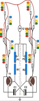
Many series parallel connected could be configured with this transistor astable circuit as shown in the following image

The next image shows how series parallel LED string lights could be arranged using the same multivibrator flasher concept for decorating a Christmas tree or for making a Christmas star.
Parts Required for the proposed LED flasher circuit using transistor AMV
- You will require the following very few numbers of components to build this circuit: Resistors ¼ watt, CFR, 5%
- R1 and R2 = 22 K,
- Potentiometers = 47 K,
- LED series resistors are all = 150 Ohms,
- LED RANDOM COLORED 5mm = 40 nos.
- Capacitors Electrolytic Radial
- C1 and C2 = 10 µF / 25 Volts,
- Transistors, General purpose
- T2 and T2 = BC 547 B
- General Purpose Board = Small piece 4” by 4”
How to Build a LED String Light AMV Flasher?
The construction of this LED flasher is very simple and is finished through the following simple steps:
In the given general purpose board, begin by inserting the two transistors somewhere around the center of the board.
Keep at least an inch of space in between them.
Solder and cut of their leads cleanly. Next fill the board with the resistors and the capacitors.
As above solder and cut their leads with the help of a nipper. Now go on interconnecting their soldered leads as shown in the circuit diagram.
The entire procedure should take not more than ½ an hour. This concludes the circuit board assembly.
Take a suitable plastic enclosure, drill appropriate holes for the potentiometers on its front panel.
Fix the potentiometers into these holes and connect them to the relevant points of the circuit board with the help of flexible wires as per the circuit schematic.
How to make the LED Series Connections?
To complete the LED string wiring just go through the following points:
In one of my previously written articles you can find a detailed discussion regarding the method of connecting the LEDs in series and then in parallel.
Just follow the circuit description of the article and complete the construction of two LED strings. Or alternatively you may just do it as per the wiring diagram of the LED connections in this article itself.
Ultimately you will find that there are two negative points coming out of the two LED strings and a common positive.
How to Test it?
With the help of the given LED wig wag flasher schematic you may proceed the testing of the unit in the following manner:
Connect by soldering the LED string outputs to the appropriate points of the circuit board.
Finally connect a 12 supply to the completed circuit assembly, instantly the whole of the LED string will start flashing displaying a true fairy light effect.
This LED string light may be positioned appropriately over the wind shield of your car for a nice little decoration.
The potentiometer controls may be optimized as per your taste to get more amazing results from the circuit.
Building a Small LED Christmas Star

The above explained transistor astable circuit can be used for making a beautiful looking, LED studded, flashing Christmas star, as shown in the above GIF image.


Questions & Answers
Dear Sir;
Let me say that I very much appreciate your concise circuit description and the simplicity of your designs. I built the above circuit after reading many of your articles and, just as you said, it came to life immediately flashing vibrant colors and actually responded to adjustments of p1 and p2…thank you.
Thank you Dan, I am glad you could make it successfully….please keep up the good work!
It may be possible by using higher rated transistors, such as TIP122, 8050, 2N2222 etc
Hello, and thanks for all you do here!
I need to put flashing strobes on the back of my dump truck. This is a 12 volt automotive application. I plan to use either 2 or 4 lights, 6 inch oval commercial lights, for this with 10 leds in each light. Can you do an article on combining the wigwag circuit above with the 2 transistor strobe circuit? I’ve been trying to figure it out but have not had success.
Thank you very much!
Todd
Hi, thanks, I have uploaded the design at the end of this post:
https://www.homemade-circuits.com/2012/01/how-to-make-any-light-strobe-light.html
I have attached a circuit please let me know what change should i make to stop glowing LED when no battery attached.Please help
https://1drv.ms/i/s!AtIIpoX_u7CWvgQTlGVzN3AkV7N_
if Vdd is not the battery positive, then make sure that the IC 555 gets the supply only the battery.
and ignore my previous suggestion of connecting LED with the base of Q6…it is not required..instead simply connect the yellow LED from Vdd to pin#7 of the charger IC via a resistor.
assuming Vdd is the battery positive, and pin#7 of TN5002 is zero when battery is charging, and logic high when battery is fully charged, you need to do the following changes in the circuit:
remove all the transistors and the associated resistors…. except Q6.
replace Q6 with a PNP such BC557, emitter to capacitor, collector to base.
connect the yellow LED in series with the base this Q6 (anode towards base, cathode towards R3.
That's all this will hopefully satisfy your requirement
Actually i need yellow LED which will glow when no battery that works fine but When no battery the 555 Green LED remain solid ON as its should be off.
When battery attach it flashes its working ok and wehn full it stays flashing as it should be solid on.I am attaching my updated circuit please suggest.
So two issues when no battery green should be off and when batt full it should be solid on.
https://1drv.ms/i/s!AtIIpoX_u7CWvgbzO0ewaEviA9fG
what do you get at pin#7 of the charger IC when there's no battery??
When no battery what will happen?
LED will be OFF
Hello;
I am new in this field i need a simple single LED flasher/Solid circuit that accepts 3 types of input signal from a circuit one is positive +5v to gnd and other is -5v to gnd when +5 signal input to arduino it should solid ON and when -5v signal input the LED starts flashing LED at rate of 2sec and when no signal (below 2v) LED off.Please reply at faizan.hamayun@hotmail.com
you can try the following concept and change it according to your specifications