In this post I have explained 4 easy to build, compact simple transformerless power supply circuits. All the circuits presented here are built using capacitive reactance theory for stepping down the input AC mains voltage. All the designs presented here work independently without any transformer, or no transformer.
The Transformerless Power Supply Concept
As the name defines, a transformerless power supply circuit provides a low DC from the mains high voltage AC, without using any form of transformer or inductor.
It works by using a high voltage capacitor to drop the mains AC current to the required lower level which may be suitable for the connected electronic circuit or load.
The voltage specification of this capacitor is selected such that it's RMS peak voltage rating is much higher than the peak of the AC mains voltage in order to ensure safe functioning of the capacitor. An example capacitor which is normally used transformerless power supply circuits is shown below:
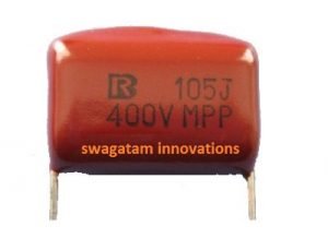
This capacitor is applied in series with one of the mains inputs, preferably the phase line of the AC.
When the mains AC enters this capacitor, depending on the value of the capacitor, the reactance of the capacitor comes into action and restricts the mains AC current from exceeding the given level, as specified by the value of the capacitor.
However, although the current is restricted the voltage isn't, therefore if you measure the rectified output of a transformerless power supply you will find the voltage to be equal to the peak value of the mains AC, that's around 310V, and this could be alarming for any new hobbyist.
But since the current may be sufficiently dropped level by the capacitor, this high peak voltage could be easily tackled and stabilized by using a zener diode at the output of the bridge rectifier.
The zener diode wattage must be appropriately selected according to the permissible current level from the capacitor.
WARNING: BE EXTREMELY CAREFUL WHILE TESTING THE CIRCUITS EXPLAINED BELOW SINCE THEY ARE NOT ISOLATED FROM AC MAINS, AND CAN PRODUCE LETHAL ELECTRIC SHOCK IF TOUCHED DIRECTLY IN AN UNCOVERED AND POWERED CONDITION. MAKE SURE TO PROPERLY INSULATE ALL THE POINTED OR EXPOSED CONNECTIONS OF THE WIRING. WE STRICTLY CAUTION YOU THAT YOU BUILD THESE CIRCUITS ONLY IF YOU ARE AWARE OF THE DANGERS OF MAINS AC AND KNOW HOW TO MAINTAIN EXTREME SAFETY AGAINST IT.
NOTE: The transformerless power supply circuits I have explained below are specifically intended to be used as cheap and compact power supply alternatives for powering small circuits. For maximum safety the user must ensure that the whole assembly is enclosed inside a well insulated box such as a plastic box. These circuits are NOT intended to be used as AC to DC adapters for powering external gadgets.
Advantages of using a Transformerless Power Supply Circuit
The idea is cheap yet very effective for applications that require low power for their operations.
Using a transformer in DC power supplies is probably quite common and we have heard a lot regarding it.
However one downside of using a transformer is that you cannot make the unit compact.
Even if the current requirement for your circuit application is low, you have to include a heavy and bulky transformer making things really cumbersome and messy.
The transformerless power supply circuit described here, very efficiently replaces a usual transformer for applications which require current below 100 mA.
Here a high voltage metalized capacitor is used at the input for the required stepping down of the mains power and the preceding circuit is nothing but just simple bridge configurations for converting the stepped down AC voltage to DC.
The circuit shown in the diagram above is a classic design may be used as a 12 volts DC power supply source for most electronic circuits.
However having discussed the advantages of the above design, it will be worth focusing on a few serious drawback this concept may include.
Disadvantages of a Transformerless Power Supply Circuit
First, the circuit is unable to produce high current outputs, but that won’t make an issue for most of the applications.
Another drawback that certainly needs some consideration is that the concept does not isolate the circuit from dangerous AC mains potentials.
This drawback can have serious impacts for designs which have terminated outputs or metal cabinets, but won’t matter for units which have everything covered up in a non-conducting housing.
Therefore, new hobbyists must work with this circuit very carefully to avoid any electrical casualty. The last but not the least, the above circuit allows voltage surges to enter through it, which may cause serious damage to the powered circuit and to the supply circuitry itself.
However in the proposed simple transformerless power supply circuit design this drawback has been reasonably tackled by introducing different types of stabilizing stages after the bridge rectifier.
This capacitor grounds instantaneous high voltage surges, thus efficiently safeguarding the associated electronics with it.
How the Circuit Works
The working of this transformless power supply can be understood with the following points:
- When mains AC mains input is switched ON, capacitor C1 blocks the entry of the mains current and restricts it to a lower level as determined by the reactance value of C1. Here it may be roughly assumed to be around 50mA.
- However, the voltage is not restricted, and therefore the full 220V or whatever may be at the input is allowed to reach the subsequent bridge rectifier stage.
- The bridge rectifier rectifies this 220V C to a higher 310V DC, due to the RMS to peak conversion of the AC waveform.
- This 310V DC is instantly reduced to a low level DC by the next zener diode stage, which shunts it to the zener value. If a 12V zener is used, this will become 12V and so on.
- C2 finally filters the 12V DC with ripples, into a relatively clean 12V DC.
1) Basic Transformerless Design
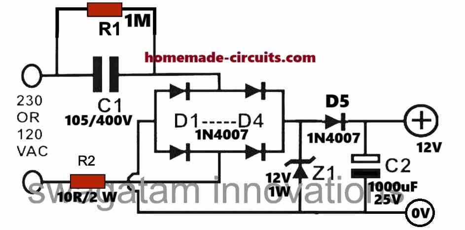
Let's try to understand the function of each of the parts used in the above circuit, in greater details:
- The Capacitor C1 becomes the most important part of the circuit since it is the one that reduces the high current from the 220 V or 120 V mains to the desired lower level, to suit the output DC load. As a rule of thumb every single single microFarad from this capacitor will provide around 50 mA current to the output load. This means, a 2uF will provide 100 mA and so on. If you wish to learn the calculations more precisely you can refer to this article.
- The resistor R1 is used for providing a discharge path for the high voltage capacitor C1 whenever the circuit is unplugged from the mains input. Because, C1 has the ability to store the 220 V mains potential in it when it is detached from the mains, and could risk a high voltage shock to whoever touches the plug pins. R1 quickly discharges the C1 preventing any such mishap.
- Diodes D1---D4 work like a bridge rectifier for converting the low current AC from the C1 capacitor into a low current DC. The capacitor C1 restricts the current to 50 mA but does not restrict the voltage. This implies that the DC at the the output of the bridge rectifier is the peak value of the 220 V AC. This can be calculated as: 220 x 1.41 = 310 V DC approximately. So we have 310 V, 50 mA at the output of the bridge.
- However, the 310V DC may be too high for any low voltage device except a relay. Therefore, an appropriately rated zener diode is used for shunting the 310V Dc into the desired lower value, such as 12 V, 5 V, 24 V etc, depending on the load specs.
- Resistor R2 is used as a current limiting resistor. You may feel, when C1 is already there for limiting the current why do we need the R2. It is because, during the instantaneous power switch ON periods, meaning when the input AC is first applied to the circuit, the capacitor C1 simply acts like a short circuit for a few milliseconds. These few initial milliseconds of the switch ON period, allows the full AC 220 V high current to enter the circuit, which may be enough to destroy the vulnerable DC load at the output. In order to prevent this we introduce R2. However, the better option could be to use an NTC in place of R2.
- The C2 is the filter capacitor, which smoothens the 100 Hz ripples from the rectified bridge to a cleaner DC can be any value between 100uF/25V to 1000uF/25V.
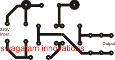
PCB Layout for the above explained simple transformerless power supply is shown in the following image. Please note that I have included a space for an MOV also in the PCB, at the mains input side.
Improving the Design
The above transformerless design looks simple, but it has some unavoidable downsides. The resistor R2 is mandatory in the circuit, otherwise the zener diode may burn instantly. However, adding the resistor R2 causes a significant drop in the output current, and there's also some serious dissipation through the resistor R2, making the circuit somewhat inefficient.
The idea to make sure that R2 is as low as possible, yet the entire circuit remains completely safe from all possible electrical hazards.
For this, we reinforce the zener diode with a high voltage transistor wired in the crowbar format, as shown in the following diagram:
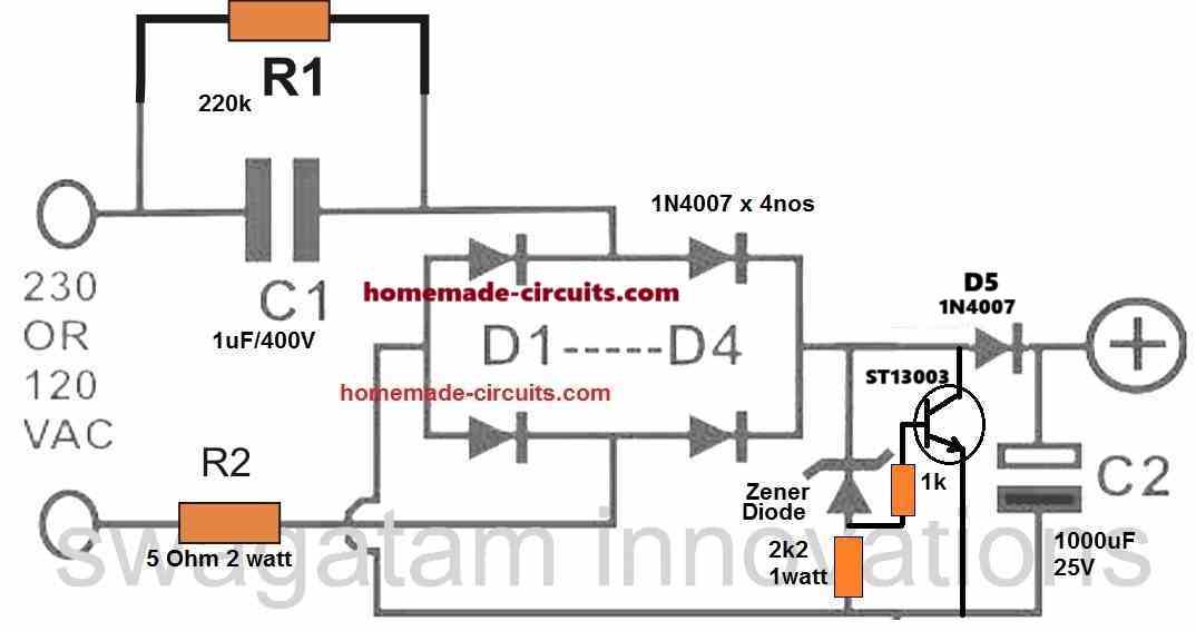
The design looks entirely fail-proof, yet provides a perfectly stabilized output. The power transistor ST13003 is used like a shunting device, which grounds the entire power from the capacitor C1 as soon as the output DC from the bridge tries to reach above the zener diode level.
In this situation, the transistor conducts and shorts circuits the DC causing the voltage to drop.
When the voltage drops, the zener stops conducting switching OFF the transistor, and the cycle keeps repeating at a fast rate, enabling a stabilized DC output voltage that is almost equal to the zener voltage value.
If you do not wish to include the power transistor, you can also modify first design in the following manner:
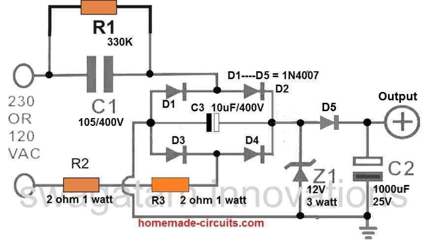
Here we have introduced 3 improvements in the circuit. We have used two current limiting resistor through R2 and R3, so that the surge current is shared across both the resistors uniformly. We have introduced C3 which helps to ground and absorb the initial switch ON surge current to a great extent causing less stress on the zener diode.
We have also increased the rating of the zener diode to 3 watts so that it does not burn under any circumstances.
You can further improve the above transformerless power supply design by replacing R2 and R3 with a single 5 ohm NTC thermistor.
How to Calculate the above Circuit
Assumptions:
Let's assume we have the following parameters in hand:
- Output Voltage (Vout): 12V DC.
- Output Current (Iout): 100mA.
- Input AC Voltage: Either 230V RMS or 120V RMS.
- Zener Diode Voltage (Z1): 12V.
- Frequency: 50Hz (for 230V) or 60Hz (for 120V).
Step 1: Current through Capacitor C1
The capacitor C1 limits the current in the circuit. Current through a capacitor in an AC circuit is calculated using the formula:
Ic = Vac × 2 × π × f × C1
Where:
- Vac = RMS voltage across the capacitor (approximately equal to the input AC voltage).
- f = AC frequency (50Hz or 60Hz).
- C1 = Capacitance in farads.
To supply Iout = 100mA, the required Ic must be slightly higher to account for losses and diode drops. Assume Ic ≈ 110mA.
Step 2: Calculate C1
Using the formula for C1:
C1 = Ic / (2 × π × f × Vac)For 230V RMS (50Hz):
C1 = 0.11 / (2 × 3.1416 × 50 × 230) ≈ 1.52 µF
For 120V RMS (60Hz):
C1 = 0.11 / (2 × 3.1416 × 60 × 120) ≈ 2.43 µF
Choose standard values: 1.5µF (for 230V) or 2.5µF (for 120V). Use an X-class capacitor rated for at least 400V AC.
Step 3: Safety Resistors R1 and R2
Resistors R1 discharge C1 when the circuit is powered off. Discharge time constant (τ) is given by:
τ = R1 × C1

For a discharge time of 1 second:R1 = τ / C1
For C1 = 1.5µF (230V):
R1 = 1 / (1.5 × 10⁻⁶) ≈ 666,667Ω (use 680kΩ standard value).Use two 680kΩ resistors in parallel for R1 rated at least 1/4W.
Step 4: Zener Diode Z1
The Zener diode regulates the output voltage. For a 12V output use a Zener diode with:
- Zener Voltage: 12V.
- Power Rating: At least 0.5W.
Power dissipated in the Zener diode is:
Pz = (Ic - Iout) × VzSubstitute values:
Pz = (0.11 - 0.1) × 12 ≈ 0.12W
Choose a Zener diode with a power rating of 0.5W for reliability.
Step 5: Smoothing Capacitor C2
The smoothing capacitor filters the rectified output. To reduce ripple voltage use the formula:
Vripple = Iout / (f × C2)Rearranging for C2:
C2 = Iout / (f × Vripple)

For Vripple = 1V (acceptable for 12V output):

C2 = 0.1 / (100 × 1) = 1000µF
Choose a capacitor rated for at least 25V.
Step 6: Rectifier Diodes (D1 to D4)
Use 1N4007 diodes for rectification. These are rated for 1A current and 1000V reverse voltage sufficient for this circuit.
Step 7: Optional Series Resistor R3
Resistor R2 + R3 limits inrush current during startup. Use a value around 10Ω rated for 1W.
Final Component Values:
- C1: 1.5µF (for 230V) or 2.5µF (for 120V), X-class capacitor.
- R1: 680kΩ, 1/4W each.
- Z1: 12V Zener diode, 0.5W.
- C2: 1000µF, 25V electrolytic capacitor.
- D1 to D4: 1N4007 diodes.
- R2 + R3 (optional): 10Ω, 1W.
The above design can be improved even further by doing the following modifications:
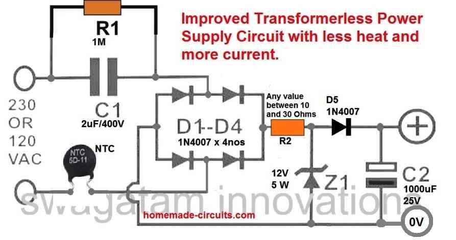
You can see we have entirely removed the capacitor across the bridge rectifier which makes the load on the zener diode 50% less, creating 50% less heat.
The filter capacitor can be seen after the diode D5 which means the capacitor voltage is much reduced to only 25V and the filtration is increased to a very high level due to the high value of 1000 uF.
Another Simple Transformerless Power Supply for long LED Strings
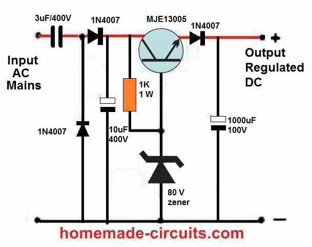
The above transformerless power supply circuit uses an MJE13005 transistor as an emitter follower regulator with a base zener diode to regulate the output voltage. The input side includes a 3uF/400V capacitor to limit the maximum output current to around 150 mA, and two diodes (horizontal and vertical) are used for rectification, converting AC voltage to pulsating DC voltage.
Example Circuit for LED Decoration Light Application
The following transformerless or capacitive power supply circuit could be used as an LED lamp circuit for illuminating minor LED circuits, such as small LED bulbs or LED string lights.
Remember, since the circuit is not isolated from AC mains the whole wiring can carry lethal AC mains voltages. Please build it only if you exactly know how to correctly insulate the circuit using plastic covers and plastic sleeves. Do it at your own risk.
The idea was requested by Mr. Jayesh:
Requirement Specifications
The string is made up of about 65 to 68 LED of 3 Volt in series approximately at a distance of let us say 2 feet ,,, such 6 strings are roped together to make one string so the bulb placement comes out to be at 4 inches in final rope . so over all 390 - 408 LED bulbs in final rope.
So please suggest me best possible driver circuit to operate
1) one string of 65-68 string.
or
2) complete rope of 6 strings together.
we have another rope of 3 strings.The string is made up of about 65 to 68 LED of 3 Volt in series approximately at a distance of let us say 2 feet , such 3 strings are roped together to make one string so the bulb placement comes out to be at 4 inches in final rope . so over all 195 - 204 LED bulbs in final rope.
So please suggest me best possible driver circuit to operate
1) one string of 65-68 string.
or
2) complete rope of 3 strings together.
Please suggest the best robust circuit with surge protector and advice any additional things to be connected to protect the circuits.
and please see that circuit diagrams are with values required for the same as we are not at all technical person in this field.
Circuit Design
The driver circuit shown below is suitable for driving any LED bulb string having less than 100 LEDs (for 220V input), each LED rated at 20mA, 3.3V 5mm LEDs:
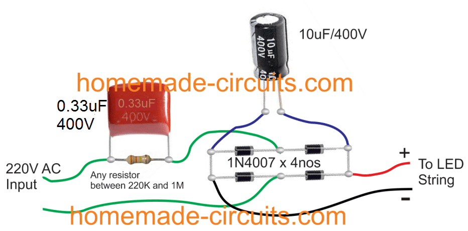
Here the input capacitor 0.33uF/400V decides the amount of current supplied to the LED string. In this example it will be around 17mA which is just about right for the selected LED string.
If a single driver is used for more number of similar 60/70 LED strings in parallel, then simply the mentioned capacitor value could be proportionately increased for maintaining optimal illumination on the LEDs.
Therefore for 2 strings in parallel, the required value would be 0.68uF/400V, for 3 strings you could replace it with a 1uF/400V. Similarly for 4 strings this would need to be upgraded to 1.33uF/400V, and so on.
Important: Although I have not shown a limiting resistor in the design, it would be a good idea to include a 33 Ohm 2 watt resistor in series with each LED string for added safety. This could be inserted anywhere in series with the individual strings.
WARNING: ALL THE CIRCUITS MENTIONED IN THIS ARTICLE ARE NOT ISOLATED FROM MAINS AC, THEREFORE ALL THE SECTIONS IN THE CIRCUIT ARE EXTREMELY DANGEROUS TO TOUCH WHEN CONNECTED TO MAINS AC........
Another Basic Capacitive Power Supply Circuit with Zener Protection
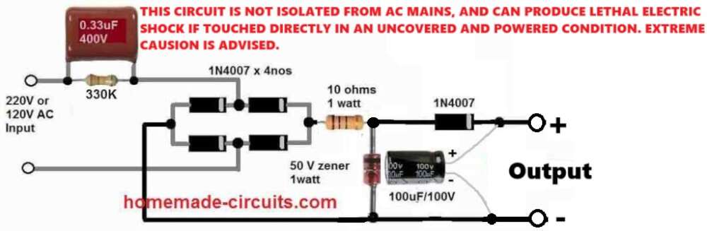
The above explained power supply circuit require a transformer for stepping down the mains AC voltage to lower levels such as 12V or 24V or 50V. They require transformer since they are supposed to handle higher amounts of current in Ampere range.
However, for low current requirements in the mA range, a transformerless power supply generally can work well. A simple general purpose transformerless power supply circuit is shown below.
This design can deliver an output of fixed voltage between 3 V and 90V depending on the zener diode value which can be selected as per the output voltage requirement.
One big disadvantage of this type transformerless power supply is that, these are not isolated from the input AC mains, and therefore contains a floating high mains voltage which can inflict a lethal electric shock if the circuit is touched in an uncovered, powered condition.
The output current is decided by the value of the input capacitor which is a 0.33uF here. As a rule of thumb every 0.5 uF capacitor will be able to deliver an output current of 30 mA. This means a 0.33uF would be able to deliver an output current of around 20 mA.
WARNING: BUILD THIS CIRCUIT ONLY IF YOU ARE AWARE OF THE DANGERS OF MAINS AC AND KNOW HOW TO MAINTAIN EXTREME PRECAUTIONS AGAINST IT. BE EXTREMELY CAREFUL WHILE TESTING THIS CIRCUIT SINCE IT IS NOT ISOLATED FROM AC MAINS, AND CAN PRODUCE LETHAL ELECTRIC SHOCK IF TOUCHED DIRECTLY IN AN UNCOVERED AND POWERED CONDITION.MAKE SURE TO PROPERLY INSULATE ALL THE POINTED OR EXPOSED CONNECTIONS OF THE FINAL ASSEMB
2) Upgrading to Voltage Stabilized Transformerless Power Supply
Now let's see how an ordinary capacitive power supply may be transformed into a surge free voltage stabilized or variable voltage transformerless power supply applicable for almost all standard electronic loads and circuits. The idea was requested by Mr. Chandan Maity.
Technical Specifications
If you remember, I communicated you sometime before with comments at your blog.
The Transformerless circuits are really good and I tested couple of those and running 20W, 30W LED.Now, I am trying to add some controller, FAN and LED all together , hence, I need a dual supply.
The rough specification is:
Current rating 300 mAP1= 3.3-5V 300mA ( for controller etc)P2= 12-40V (or higher range), 300mA (for LED)
I thought to use your 2nd circuit as mentionedhttps://www.homemade-circuits.com/2012/08/high-current-transformerless-power.html
But, I am not able to freeze the way how to get 3.3V without using extra capacitor. 1. Can, a second circuit may be placed from the output of first one? 2. Or, a second TRIAC, bridge to be placed in parallel with first one, after capacitor to get 3.3-5V
I shall be glad if you kindly help.
Thanks,
The Design
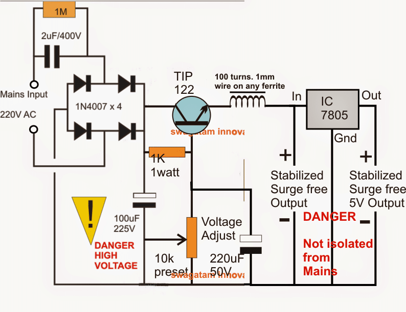
The function of the various components used across the various stages of the above shown voltage controlled circuit may be understood from the following points:
The mains voltage is rectified by the four 1N4007 diodes and filtered by the 10uF/400V capacitor.
The output across the 10uF/400V now reaches around 310V which is the peak rectified voltage achieved from the mains.
The voltage divider network configured at the base of the TIP122 makes sure that this voltage is reduced to the expected level or as required across the power supply output.
You can also use MJE13005 in place of TIP122 for better safety.
If a 12V is required the 10K pot may be set to achieve this across the emitter/ground of the TIP122.
The 220uF/50V capacitor ensures that during switch ON the base is rendered a momentary zero voltage in order to keep it switched OFF and safe from the initial surge in-rush.
The inductor further ensures that during the switch ON period the coil offers a high resistance and stops any inrush current to get inside the circuit, preventing a possible damage to the circuit.
For achieving a 5V or any other attached stepped down voltage, a voltage regulator such as the shown 7805 IC may be used for achieving the same.
Circuit Diagram
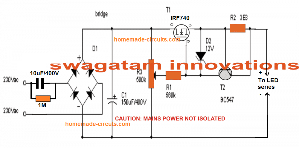
Using MOSFET Control
The above circuit using emitter follower can be further enhanced by applying a MOSFET source follower power supply, along with a supplemental current control stage using BC547 transistor.
The complete circuit diagram can be seen below:
Video Proof of Surge Protection
3) Zero Crossing Transformerless Power Supply Circuit
The third interesting explains the importance of a zero crossing detection in capacitive transformerless power supplies in order to make it completely safe from the mains switch ON inrush surge currents. The idea was proposed by Mr. Francis.
Technical Specifications
I have been reading about the transformer less power supply articles on your site with great interest and if I am understanding correctly the main problem is the possible in-rush current in the circuit upon switching-on, and this is caused because switching-on does not always occur when the cycle is at zero volts (zero crossing).
I am a novice in electronics and my knowledge and practical experience are very limited, but if the problem can be solved if zero crossing is implemented why not use a zero crossing component to control it such as an Optotriac with zero crossing.
The input side of the Optotriac is low power therefore a low power resistor can be used to lower the mains voltage for Optotiac operation. Therefore no capacitor is used at the Optotriac’s input. The capacitor is connected on the output side which will be switched on by the TRIAC which turns on at zero crossing.
If this is applicable it will also solve high current requirement problems, since the Optotriac in turn can operate another higher current and/or voltage TRIAC without any difficulty. The DC circuit connected to the capacitor should no longer have the in-rush current problem.
It would be nice to know your practical opinion and thank you for reading my mail.
Regards,
Francis
The Design
As rightly pointed out in the above suggestion, an AC input without a zero crossing control can be a major cause of a surge current inrush in capacitive transformerless power supplies.
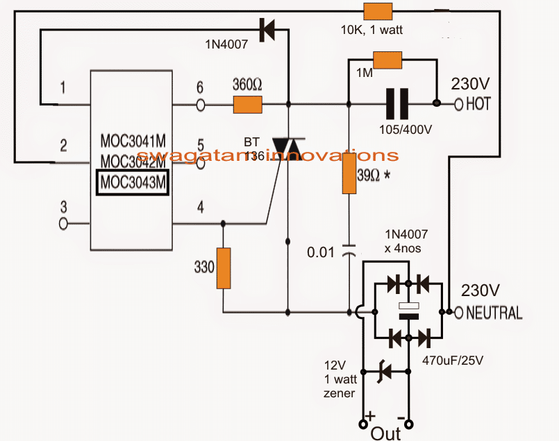
Today with the advent of sophisticated triac driver opto-isolators, switching an AC mains with zero crossing control is no longer a complex affair, and can be simply implemented using these units.
About MOCxxxx Opto-couplers
The MOC series triac drivers come in the form of optocouplers and are specialists in this regard and can be used with any triac for controlling AC mains through a zero crossing detection and control.
The MOC series triac drivers include MOC3041, MOC3042, MOC3043 etc all these are almost identical with their performance characteristics with only minor differences with their voltage spces, and any of these can be used for the proposed surge control application in capacitive power supplies.
The zero crossing detection and execution are all internally processed in these opto driver units and one has to only configure the power triac with it for witnessing the intended zero crossing controlled firing of the integrated triac circuit.
Before investigating the surge free triac transformerless power supply circuit using a zero crossing control concept let's first understand briefly regarding what's a zero crossing and its involved features.
What is Zero Crossing in AC Mains
We know that an AC mains potential is composed of voltage cycles which rise and fall with changing polarity from zero to maximum and vice versa across the given scale.
For example in our 220V mains AC, the voltage switches from 0 to +310V peak) and back to zero, then forwarding downwards from 0 to -310V, and back to zero, this goes on continuously 50 times per second constituting a 50 Hz AC cycle.
When the mains voltage is near its instantaneous peak of the cycle, that is near 220V (for a 220V) mains input, it's in the strongest zone in terms of voltage and current, and if a capacitive power supply happens to be switched ON during this instant, the entire 220V can be expected to break through the power supply and the associated vulnerable DC load.
The result could be what we normally witness in such power supply units.... that is instant burning of the connected load.
The above consequence may be commonly seen only in capacitive transformerless power supplies because, capacitors have the characteristics of behaving like a short for a fraction of a second when subjected to a supply voltage, after which it gets charged and adjusts to its correct specified output level
Coming back to the mains zero crossing issue, in a converse situation while the mains is nearing or crossing the zero line of its phase cycle, it can be considered to be in its weakest zone in terms of current and voltage, and any gadget switched ON at this instant can be expected to be entirely safe and free from a surge inrush.
Therefore if a capacitive power supply is switched ON in situations when the AC input is passing through its phase zero, we can expect the output from the power supply to be safe and void of a surge current.
How it Works
The circuit shown above utilizes a triac optoisolator driver MOC3041, and is configured in such a way that whenever power is switched ON, it fires and initiates the connected triac only during the first zero crossing of the AC phase, and then keeps the AC switched ON normally for rest of the period until power is switched OFF and switched ON again.
Referring to the figure we can see how the tiny 6-pin MOC 3041 IC is connected with a triac for executing the procedures.
The input to the triac is applied through a high voltage, current limiting capacitor 105/400V, the load can be seen attached to the other end of the supply via a bridge rectifier configuration for achieving a pure DC to the intended load which could an LED.
How Surge Current is Controlled
Whenever power is switched ON, initially the triac stays switched OFF (due to an absence of the gate drive) and so does the load connected to the bridge network.
A feed voltage derived from the output of the 105/400V capacitor reaches the internal IR LED through the pin1/2 of the opto IC.
This input is monitored and processed internally with reference to the LED IR light response.... and as soon the fed AC cycle is detected reaching the zero crossing point, an internal switch instantly toggles and fires the triac and keeps the system switched ON for the rest of the period until the unit is switched OFF and ON yet again.
With the above set up, whenever power is switched ON, the MOC opto isolator triac makes sure that the triac is initiated only during that period when the AC mains is crossing the zero line of its phase, which in turn keeps the load perfectly safe and free from the dangerous surge in rush.
Improving the above Design
A comprehensive capacitive power supply circuit having a zero crossing detector, a surge suppressor and voltage regulator is discussed here, the idea was was submitted by Mr. Chamy
Designing an Improved Capacitive Power Supply Circuit with Zero Crossing Detection
Hello Swagatam.
This is my zero crossing, surge protected capacitive power supply design with voltage stabilizer,i will try to list all of my doubts.
(I know this will be expensive for the capacitors,but this is only for testing purposes)
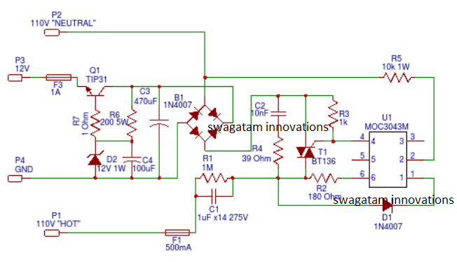
1-I'm not sure if the BT136 haves to be changed for a BTA06 for accommodating more current.
2-The Q1 (TIP31C) can handle only 100V Max. Maybe it should be changed for a 200V 2-3A transistor?,like the 2SC4381.
3-R6 (200R 5W),I know this resistor is pretty small and its my
fault,i actually wanted to put a 1k resistor.But with an 200R 5W
resistor it would work?
4-Some resistors have been changed following your recommendations to make it 110V capable.Maybe the 10K one needs to be smaller?
If you know how to make it work correctly,i will be very happy to correct it.If it works i can make a PCB for it and you could publish it in your page (For free of course).
Thank you for taking the time and viewing my full of faults circuit.
Have a nice day.
Chamy
Assessing the The Design
Hello Chamy,
your circuit looks OK to me. Here are the answers to your questions:
1) yes BT136 should be replaced with a higher rated triac.
2) TIP31 can be replaced with a 200V Darlington transistor such as BU806 etc otherwise it might not work properly.
3) when a Darlington is used the base resistor could be high in value, may be a 1K/2 watt resistor would be quite OK.
However the design by itself looks like an overkill, a much simpler version can be seen below https://www.homemade-circuits.com/2016/07/scr-shunt-for-protecting-capacitive-led.html
Regards
Swagatam
Reference:
4) Switching Transformerless Power Supply using IC 555
This 4rth simple yet smart solution is implemented here using IC 555 in its monostable mode to control in rush surge in a transfomerless power supply via a zero crossing switching circuit concept, wherein the input power from the mains is allowed to enter the circuit only during the zero crossings of the AC signal, thereby eliminating the possibility of surge inrushes. The idea was suggested by one of the avid readers of this blog.
Technical Specifications
Would a zero cross transformerless circuit work to prevent the initial inrush current by not allowing turn on until the 0 point in the 60/50 hertz cycle?
Many solid state relays which are cheap, less then INR 10.00 and have this ability built in them.
Also I would like to drive 20watt leds with this design but am unsure how much current or how hot capacitors will get I suppose it depends on how the leds are wired series or parallel, but lets say the capacitor is sized for 5 amps or 125uf will the capacitor heat up and blow???
How does one read capacitor specs to determine how much energy they can dissipate.
The above request prompted me to look for a related design incorporating a IC 555 based zero crossing switching concept, and came across the following excellent transformerless power supply circuit which could be used for convincingly eliminating all possible chances of surge inrush.
What's a Zero Crossing Switching:
It's important to learn this concept first before investigating the proposed surge free transformerless circuit.
We all know how a sine wave of an AC mains signal looks like. We know that this sine signal starts from a zero potential mark, and exponentially or gradually rises to the peak voltage (220 or 120) point, and from there exponentially reverts to the zero potential mark.
After this positive cycle, the waveform dips and repeats the above cycle but in the negative direction until it comes back yet again to the zero mark.
The above operation happens about 50 to 60 times per second depending upon the mains utility specs.
Since this waveform is what enters the circuit, any point in the waveform other than the zero, presents a potential danger of a switch ON surge due to the involved high current in the waveform.
However the above situation can be avoided if the load confronts the switch ON during the zero crossing, after which the rise being exponential doesn't pose any threat to the load.
This is exactly what we have tried to implement in the proposed circuit.
Circuit Operation
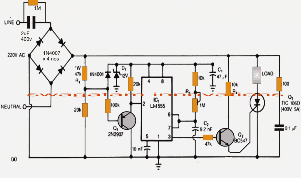
Referring to the circuit diagram below, the 4 1N4007 diodes form standard bridge rectifiers configuration, the cathode junction produces a 100Hz ripple across the line.
The above 100Hz frequency is dropped using a potential divider (47k/20K) and applied to the positive rail of the IC555. Across this line the potential is appropriately regulated and filtered using D1 and C1.
The above potential is also applied to the base Q1 via the 100k resistor.
The IC 555 is configured as an monostable MV which means its output will go high every time its pin#2 is grounded.
For the periods during which the AC mains is above (+)0.6V, Q1 stays switched OFF, but as soon as the AC waveform touches the zero mark, that is reaches below the (+)0.6 V, Q1 switches ON grounding pin#2 of the IC and rendering a positive output of the IC pin#3.
The output of the IC switches ON the SCR and the load and keeps it switched ON until the MMV timing elapses, to begin a new cycle.
The ON time of the monostable can be set by varying the 1M preset.
Greater ON time ensures more current to the load, making it brighter if it's an LED, and vice versa.
The switch ON conditions of this IC 555 based transformerless power supply circuit is thus restricted only when the AC is near zero, which in turn ensures no surge voltage each time the load or the circuit is switched ON.
Circuit Diagram
For LED Driver Application
If you are looking for a transformerless power supply for LED driver application at commercial level, then probably you can try the concepts explained here.
Transformerless 220 V to 50 V Converter Circuit
The bridge-rectifier BR1 receives the AC voltage from PL1 and produces a fullwave output of about 300 volts DC. A sequence of 5 volt pulses are produced by the network R1, R2, D1, D3, and D4 and serve two crucial purposes:
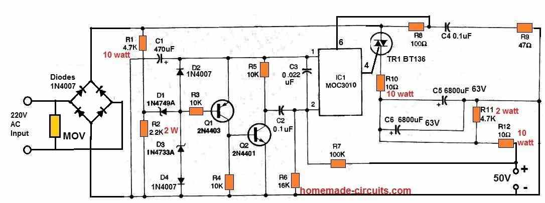
Firstly, using D2 and C1, the pulses are employed as a 5-volt power supply for the monostable circuit and pulse shaping.
Secondly, the pulses activate the monostable circuit formed of C2 and R6, the pulse-shaping circuit consisting of Q1, Q2, and R3-R5, and the optoisolator 1C1 and power-triac TR1.
The peak output voltage is determined by resistor R2, which also controls the highest pulse width.
If the feedback network is removed the output peak voltage would be about 90 volts. The feedback configuration made up of R6, R7, and C3 reverse biases the optoisolator whenever the output voltage increases beyond 50 volts in order to get the desired 50 volt output.
The unregulated voltage then drops to zero volts, forcing TR1 to switch off. Thus, the RC feedback circuitry effectively modifies the conduction state of 1C1 to control the output voltage.
The optoisolator's current is limited by resistor R8, and C4 and R9 guarantees its constant and stable functioning.
Additionally, R10 controls the surge current that passes across TR1 whenever the power is first switched on. A low-pass filter stage with the components R10, C5, and C6 reduces ripple current.
C5 and C6 are discharged by the resistor R11 whenever the power source is switched off.
New Entry: Cheap, Surge-Free Transformerless Power Supply (Recommended)
Recently, while exploring a cheaper version of a zero crossing based surge free transformerless power circuit I happened to design the following circuit, which looks very promising.
The following figure shows the full circuit diagram. I have not yet tested it but the working looks very obvious.
The working of the circuit is very interesting.
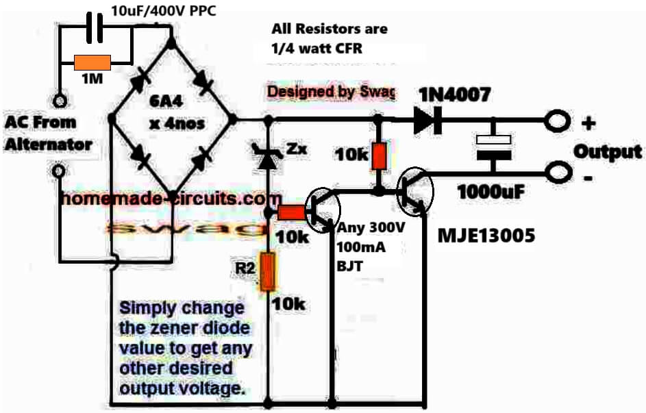
The input 10 uF capacitor drops the AC input current to 500 ma and feeds the 220 V to the bridge rectifier. The bridge rectifier rectifies the low current 220 V AC into a 310 V DC to the transistor/zener zero crossing controller circuit.
Now, as long as the output DC from the bridge is above the zener diode value, it keeps the left transistor turned ON which shorts the base of the right side transistor to ground, keeping it shut off, so the output has no voltage.
This means that, any form high voltage input surge is completely eliminated during any period of the AC cycle waveform.
However, each time the AC waveform reaches below the zener value ZX, it causes the zener diode to shut off and allow the left transistor to shut off and the right side transistor to switch ON. This in turn allows the connected load to be switched ON for these low voltage sections of the AC waveforms.
While the right side MJE transistor conducts, it delivers the low voltage DC to the 1000 uF capacitor so that the voltage is stored inside the capacitor.
This stored voltage is subsequently fed to the load for a safe and a well regulated operation of the load.
The transistor and the zener network makes sure that the load gets the required operating voltage whenever the AC input voltage for this circuit is below the selected zener value.
This ensures that the load is never subjected to a switching high voltage or high current surge, and can operate safely without any relevant concerns.



Questions & Answers
you can use a 5.1V zener in place of the shown zener, 0.22uF will not work because it won't be able to support the relay.
Hi Swagatam
Is it possible to have current in between 100mA and 200mA?
Hi Abu-Hafss,
It is possible, provided the load voltage is rated at the input mains level, otherwise most of the current would drop producing no significant enhancement in current.
No, it isn't.
Hello
is input polarity important in this design? e.g. in many european countries there is no wiring standard to dictate which wire/pole is the phase and which is the neutral. and even if there were, the plugs can just be reversed.
and if input polarity is not important could you give a brief explanation why?
many thanks
Justin Adie
For mains AC inputs the polarity is never critical because of its alernating nature which oscillates from positive to negative at the specified frequency, in your area and India it's 50Hz (50 cycles per second), therefore the polarity is undefined and becomes immaterial.
I don't quite agree completely with this comment. There may not be a difference in the operation of the circuit but if Ground is connected to LIVE/PHASE instead of NEUTRAL, inner circuit becomes vulnerable for electric shock and there is no way to prevent this 🙁
The ground connection is a different issue, we are not considering ground here, we are only discussing how the phase/neutral may be used for a given AC load.
The polarity consideration is not critical when the output is DC, just as in the above explained transformerless power supply, but is definitely crucial if an AC appliance is used such as fridge, geyser etc, and also in plug sockets, where the phase must always come through the switch in the socket…
so it doesn't matter that the filtering circuit is on the neutral (tied to ground) rather than the phase?
is that true even for electrical systems that do not tie neutral to ground?
and does that also mean that it makes sense to put fuses at both terminals of this kind of AC circuit?
It doesn't matter to the circuit operation, but certainly matters to living beings in terms of getting or avoiding a lethal shock.
Therefore when it comes to adding a fuse, it must be always added to the phase line, never to the neutral.
and therein lies the problem! In my country (France) there is _no_ way to determine visually which line is the phase and which the neutral. the plugs and sockets are not physically polarised.
so what is the recommendation? to fuse both lines?
You can simply identify them by using a line tester device, the touching the tester to the relevant lines will provide an illuminated neon indication for the phase line and no illumination for the neutral.
Please can a dimmer switch be used to regulate transformerless power supply like the ones above with no damage to the triac since load seems to be capacitive. I have built the circuit and it’s working fine now but I do not know whether it will be faulty at the long run
Yes that is possible. In fact I already have a related circuit design explaining a similar concept
https://www.homemade-circuits.com/high-current-transformerless-power/
Ok I have seen it. Thanks!
yes. however that is not practical when the power supply and device are in their container and freely movable by the consumer from socket to socket.
it is not, of course, reasonable to require a user to have a phase tester and insert it into a socket to test (and in fact for security reasons it is not quite that simple either).
i guess by not answering the question about fusing you are indicating either that it is not safe to use this circuit when there is no visual way to determine phase or you do not have an opinion on whether it is good practice (and effective) to fuse both poles.
as always, thanks for your time.
Justin, since this circuit utilizes a full wave bridge rectifier (the 4 diodes in a circle) input polarity is not an issue. All Swagatam was saying is that if you wanted to add a fuse for additional protection, then polarity would be important.
Thanks for your understanding David, yes a fuse is not essential for the above circuit since it has a DC output, but for other appliances a fuse must be added to the LIVE line so that in case it blows of no Phase current stays floating within the house electrical.
Hii…
what will be the voltage across the output terminals for this circuit, given that the Zener diode is not used for regulation?
Also, does the AC capacitor(PPC) act as the series reactance as opposed to the Series resistance(Rs) in a standard Zener Voltage regulator circuit?
The voltage will be always equal to the input mains peak, for 220V AC it would be 330V DC.
In presence of load, whether a zener or any other load, the reactance behaves like a resistance and restricts current as per the load.
I designed a transformerless power supply for 12vdc fan using 225j/400v. When it is connected the fan rotates and immediately stops but when the same fan connected to a 12vdc supply from 0-12v transformer it works perfectly. Could be as a result of lack of zero crossing. How can I correct this going forward. Please I need your help.
Try a larger filter capacitor. If still it doesn’t work then it may be due to low current.
Sir i want to replace a 12-0-12 transformer in one of my projects with this transformerless power supply you have mentioned here. I want your help in implementing it, would you please guide me on how to do it, whether i can use the same circuit mentioned above or any changes are required.
Thanks in advance
Hi Shriram, what is the current requirement of your circuit? If it's above 100mA then capacitive power supplies as described above should not be used
How much AMPERE is this 12V transformerless,?
50mA
Do you have a 12V 1A transformerless? Or 2A
presently i don't have it.
Hi Fazal, yes you can use a 5V zener to get a 5V output from this circuit.
Hello Swagatam Majumdar.. How can I make the output of this power supply be 12V 1A?
hello Jason, getting current above 100mA is not recommended for capacitive power supplies…because it could dangerous for the connected load under those specs.
Sir
I made this circuit but sum time after r2 is burn
Help me
Jagdish, use 474/400V in place of 105/400V
have two TM-619-2 timers that work on 220v.Would like to run a 120v. Uses transformerless cap power supply. Components are .33uf cap with 1M ohm resister in parallel as well as 180 ohm resistors in series on both sides of 220v input. Bridge rectifier follows. Can you help?
you can use the same circuit with 120V also, the output result from transformerless supply would be the same as for 220V.
They also have model TM-619-1(120vac) and TM-6331(120/220vac). When I plug in the 619-2(220vac) to 120vac the timer portion will work but the power supply is suppose to convert to 24vdc to run a relay which it is not doing. I have 2 brand new and neither will switch relay running at 120vac.
you ca try increasing the value of the 0.33uF cap by putting another 0.33uF parallel to it or by replacing it with a 0.68uF/250V cap.
I did try a .47uf with no luck but will try with a .68.uf. Thx for quick response! Great name by the way Swag.
sure Pete! thanks, my pleasure:)
Above circuit can i use in your Li-ion Emergency Light Circuit with Over charge and Low Battery Cut off Features circut. Instead off cellphone charger circuit
No, it won't charge Li-ion batt
Sir. Plz give ac oprated mobile battery li – ion batt circuit
Have u made it?
my friend said we can't put resistor facing 220 volt AC
a resistor can be inserted anywhere in a circuit for suppressing surge, the position is never critical.
Hello Sir;
I want to try this circuit for Making LED series for Diwali. I try to test this circuit using Circuit design PCB software but in this software there is no 250v electrolytic capacitor so i use 200v electrolytic capacitor so it give me a voltage of approximately 13V but i am satisfy with output current . My Doubt is if i use 250v electrolytic capacitor then it will give the 12v output voltage or less than 12 . And how much watt is R1.
Please tell me some PCB design software which use AC power supply component and can run stimulation test.
Hello Deepam,
200V capacitor will also do, this voltage is not relevant to the the output voltage of the circuit, the zener diode is responsible for it.
Don't use simulators, they are very unreliable and mostly give misleading results.
R1 will be always 1/4 watt
Surprisingly in cheap led bulbs available in the market, they use 474K /250V main cap and no filter cap.and they are doing good… Now how these bulbs servibe in the 240 V mains?? thanks
Yes it's possible, I'll try to address it soon in my blog
Hi Swagtam
Can this supply be used to power up the following project:
https://www.homemade-circuits.com/2014/06/energy-saver-solder-iron-station-circuit.html
I am bit concerned about the voltage surges.
Hi Abu-Hafss,
although I too don't recommend capacitive power supplies for operating sophisticated electronic circuits, the above circuit could become relatively safer if C1 is reduced to 0.47uF/400V….the zener diode is crucial here and should not be removed from the circuit.
there isn`t 50 ohm/1w resisiton to find then what can i use to that?
the value is not critical, you can try other values such 33, 47 68, ohm etc.
why the 50ohm 1watt resistor is very hot?
It is not a calculated value, it’s only to prevent surge current to the load. You can reduce it to 20 ohms and check the difference.
I want to convert 230 or 220 vac to 5 or 6v dc without transformer so pls help me it's urgent i need for a project
you can try the circuit discussed in the above article….use a 5V zener at Z1, and 0.33uF/400V for C1
can you please explain the function of R1 and C1 ?
i mean why they are in parallel ?
R1 makes sure that C1 gets discharged immediately while someone unplugs the unit from the mains socket, thus cancelling any chance of an electric shock to the user from C1 discharge
For wat purpose the circuit can be used for……….
for powering any DC circuit below 50ma
can i use regulator ics instead of zenar dode?
what is the dc output after the rectifier, without using the zenar ( capacitor is not removed)
yes regulator ICs can be used, without a zener it would be restricted to the capacitor's breakdown voltage rating…..but that would create a lot of stress of the capacitor
Plz just tell me how capacitor contribute in step down ac voltages and what value of capacitor we will choose for 220-6v and how???plzzzz
capacitor steps down the current not the voltage…voltage is controlled by the zener diode
Can I use this circuit to power 12v computer Fan?
yes, but at a slower speed…
What should i do to maximize the speed of the fan?
add anther capacitor parallel with C1
Thank you Swagatam.. Can you give the modified circuit? Just to make sure that I make this right.
My pleasure pakol, make C1 = 2uF/400V that's all, and preferably use a 12V 2 watt zener.
Please help me.Can I use 2uF/400V for C1?
1uF/400V is not available near my area.
2uF will cause more surge current to flow into the circuit….you may use it, but make sure to employ two zener diodes in parallel each rated at 1 watt
sir can u help me to convert 230v ac to 110v ac …step down circuit
Arun, you'll need an auto-transformer for that
you can wind 300 turns of magnet wire (25SWG) over an iron laminated core (transformer E core) and connect the ends to the 220V, the 110V may be collected from anywhere at the middle of the winding
Sir good work. But what is the use of r2 50ohm 1w resistor. Can I use 100ohm resistor instead of this. Plz replay me.
Binu, it's for limiting current, you can use lower values than 50 ohms, higher values can cause increased heat for the resistor and lower current outputs
hello sir
i am tring to make supply from 220v ac to 72 v dc with 2ampere
could u please help me in it
sorry I do not have this circuit at the moment…
Hi
You can try to find a center-tapped transformer having 220V input and output 36-0-36V rated 2A or 3A. Leave the center-tap and use the remaining two terminals of the transformer with suitable diodes (bridge rectifier) and 1000µ (or more)/100V capacitor to get 72VDC.
Hello sir,
I had made this circuit and trying to get output
But whenever i connect zener diode as shown,i gain the output of 1.5v while removing the zener i get 28v so can u plzz tell me where i am getting wrong?
How could i get 12v 1a finally..?
Hello Malay, It could be due to a faulty zener diode or may be you are connecting it with a wrong polarity…try replacing it with a new one.
12a/1A from this power supply could be impractical and not recommended.
Sir i replaced 3 diodes but the problem remains same…every time the diode blows off.
Can i attach any resistor or capacitor in series to diode,and hece collect 12v power.?
the zener should be rated at 1 watt…connect a 1N4007 also in parallel to the zener to reduce the stress on the zener…the 1N4007 anode should be connected to the positive line
I tried this too but it still not working sir.
I am not getting the output.
Instead of zener,can i use any other component?
It means your capacitor is faulty…you can try 7812 IC
Sir, I have made egg incubator timer that you have written on another article, and I want to ask that, can I use this transformerless to be power supply the egg incubator timer circuit that use two 4060 ics?
Harvest, no it's not recommended and might not work….use a 12V ad to dc SMPS adapter or a transformer power supply
please sir tell me , i want 220v ac to 60v dc transformerless circuit without transistor
you can use the above shown circuit and replace the zener with a 60V zener
hai friend…how can i do my project of mobile charge sharging transfromerless+
Hi Vicky, have you previously built an SMPS circuit? if yes then you can try the following design for your requirement:
https://www.homemade-circuits.com/2014/02/220v-smps-cell-phone-charger-circuit.html
i need a transformerless in this conditions: 6V at 120VAC and 12V at 220VAC! have you circuit for this ?
just change the zener value accordingly in the above shown design…that's all is neeeded
R2 is NTC for inrush current or power resistor?
R2 is an ordinary resistor but you can definitely replace it with a suitable NTC
Hi Sir,
can i use a 10k NTC in place of R2?
and a 474 630vac mylar in place of 105 400vac capacitor?
im using it as a power supply for a 12v relay driver circuit to power a 12v dc motor, can i just also use the same power source for the 12v dc motor?
thanks,
amor
Hi Amor, yes you can try the mentioned components, it should work. If it is a relay that you want to connect at the output, you can eliminate the 12V zener, or use a 24V zener instead. Because a relay is a relatively heavy load and will never burn from a 474 capacitor’s surge, therefore the zener diode can be eliminated or a some higher value can be used.
Thank you Sir,
how about the 12vdc motor can i just tap it with the same power source? i mean one source to power both relay driver stage and a 12vdc motor load
Amor, If the motor current is within 100mA or 200mA then it might be possible otherwise I won’t recommend using a capacitive power supply
good day Sir,
Without the 12v zener the output after the rectification will be 310vdc (as mentioned above) if i eliminate the 12v zener i think it is not safe for the relay driver stage to connect in the output Sir.
another thing Sir a dc motor will be connected to the relay output which is also a 12vdc my question is can i just tap the common terminal of the relay in the above power supply?
Amor, a transistor driver stage won’t be required here. You can connect the relay coil directly at the output of the transformerless power supply, that’s the zener diode would be necessary. If your motor is a low current motor then you can tap the power from the same source otherwise not.
Thank you Swagatam.
i can not speak english fluently.
i need a transformerless in this conditions:12V,180mA
i use C1 = 2uF/400V , Z1=12V 5 watt zener
output voltage =12.3v
but,while the no-load power, Warm up zener diode.(why the zener diode Heated ! ?)
and too: make two zener diodes in parallel each rated at 1 watt. but zener diode Heated !!!why ?
plz help.thanks.
beni, a 5 watt zener is not supposed to get warm, but if it is then you can try adding a 1N4007 diode parallel with the zener in the same polarity, and check the difference.
thanks,
i adding a 1N4007 diode parallel with the zener, i use 12V 1 watt zener ,then i use 12V 5 watt zener
the power is OK.OK.
But while the no-load power(If any consumer is not connected to the circuit) Warm up zener diode.
you can keep the circuit switched OFF when there's no load connected because anyway without a load it may not be a good idea to keep the circuit switched oN
I want 12v/300ma transformer less power supply circuit diagram please send link sir
https://www.homemade-circuits.com/2014/02/simple-1-watt-to-12-watt-smps-led.html
Hi friend,
I see that in the above pic, you used 12v zener, so the output of this circuit is 12v.
I did not get 12v 1w zener so I made little changes,
Here is my alteration:
I removed zener and placed with 7812 and replaced c2 with 10uf 16v..
this is correct????
Hi friend, yes that will do, but if due to surge current 7812 blows-of then it will be a bigger lose than a 12V zener….put an NTC at the input to solve this issue
can i change the polarity of input(Line and N)?
yes you can!
Sir can I use this circuit to power your egg incubator thermostat circuit.
no you can't, either an SMPS adapter or a transformer based power supply can be used and is recommended.
Sir ,thanks for your previous reply. Can you please recommend me any of your circuits without transformer suit able for the incubator circuit.
Sonal, Would you be able to build an SMPS circuit? I don't think so.
So it's better to buy a ready made 12V 1 amp SMPS adapter and use it for the purpose
Sir I want to make an rechargeable 12v emergency light with battery level indicator without transformer plz help me
waqas, similar circuits are already present in this website please search it through the given search boxes…
hi swagatam , i made the circuit and its working i used it to power my 12vdc 3w led bulb, now how can i modify it to be used on 240V AC instead of 220v AC
Hi Davis, you can use the same circuit for 220V as well as 240V.
3 watt LED will not work with this circuit.
i have a query about out put from this circuit that if there is variation on input voltage like 220 volt to 180 volt or below, will this circuit change the out put voltage ?
NO, unless and until the input AC drops below the zener voltage value
Hi, Swagatam,
In the above simple transformerless power supply, the circuit shows a reduced DC voltage after the zener diode and a ground connection. What provides the ground. It is not connected to the neutral, so what do I ground the connection to? I'm using this with a 120vac supply and I am using a 6v zener diode. I have connected a 1n4007 across the cap and the resistor as you suggested, but I don't know how to ground the low voltage circuit. I am using the low voltage(6vdc) to power a white LED in a night light circuit. Help! Thanks!
Hi Norman, you don't have to connect anything in the indicated area, the ground symbol emphasizes the negative line in all DC circuits….so here too the symbol just signifies the negative common line in the DC section…you can simply ignore this symbol if you wished to.
Thanks for the quick response! I will build the circuit as soon as the parts arrive. Have a nice day!
OK thanks!
OK what i have learned so far:lol…. if i connect two extra Z2 and Z3 in series and parallel, will i get 24Volt-@2amp. Thank you.
you are partially correct, it will give you 24V, but not 2 amp current, because current level is determined by the input capacitor value…..you can read more on this here
https://www.homemade-circuits.com/2015/01/calculating-capacitor-current-in.html
Ok, so I just have to add extra ppc to get the amperage needed, anyways thanks to you sir, I am learning a lot.
yes that's right!!
Thank you thank you Swagatam you are the greatest, I was like 50% sure about adding extra ppc but I guessed it right lol but its all because of you sir, I am learning a lot only after I found your great site, wish I had found it sooner but its never too late BTW I never thought I will learn so much in less time, and its all because of great and kind man like you who gives hope to new beginners like me, in what we just loves to spend time on whenever we get time. God bless you sir. Looking forward to learn as much as I can. Keep up the great work, appreciated.
You are welcome Lima, keep posting your queries, your involvement will help others also to learn more… keep up the good work…
OK, surely i will(: thank you so very much sir, i just love this site… keep up..
Swagatam, thank you for your kind responses since 2013 and probably earlier!! Hats off to your consistency. I read through all the responses written on this page.
I came here to find if I can charge Li-Ion battery (The one in dead cell phone) using this circuit and you said it is not possible. But didn't get why it should not work. cell phone battery rating is 3.7v-4.2v. if we configure the circuit to give 5 to 6 v, 50mA would be more than sufficient for charging current, only thing is about auto cut-off. You had suggested cell phone charger circuit for Li-Ion batteries but should I directly connect the Li-Ion battery across 5V SMPS output. This is where I've stuck.
Other interesting note I wanted to tell others is your circuit is used in most cheap chinese mosquito zapper bats. Since it is cheap, it does not have zener diode and instead of capacitor, they have connected battery to be charged. So, I was thinking if I could use Li-Ion battery instead of Lead acid battery that they have.
Sorry, I've asked many questions and comments but please direct me to appropriate threads. and thanks for your help
Thank you Kirams, I greatly appreciate your involvement with my site!
Li-Ion cells are costly and highly efficient cells and that's why I don't recommend charging them with the above cheap transformerless type design, where even the mains is not isolated.
It is ofcourse possible to use these power supplies for charging a Li-ion cell but is not advisable.
Li-ion normally accept and work with high current, for quick charging, which the above design may be incapable of delivering therefore the overall feeling is that one should avoid using such crude and dangerous versions of power supplies rather use an SMPS or transformer based designs.
Still if you plan to try it make sure you include the zener diode, otherwise it can become even more dangerous for the cell.
Dear brother I made this power supply for my LDR light circuit. I made a PCB for that circuit including this power supply and found around 12.5 VDC across the capacitor diode. But the problem is the 12V relay is vibrating and the glow of the light is very low. When the circuit is powered from a separate DC source across the zener diode the circuit works perfect; no vibration. Is there any modification is required to use this power supply? Please advise.
Dear Rajib,
you will need to connect another capacitor parallel to C2 with a value around 1000uF/50V, this will solve the issue
Dear brother, now its working perfectly. Can I remove capacitor C2 as 1000uF/50V has been added?
Hi Rajib, C2 will help to safeguard switch ON surges better, if you want to remove it then make sure to connect an NTC thermistor at the input mains side of the power supply to prevent switch on surge into the connected circuit.
Dear Mr. Swagatam,
i have a mosquito zapper with 4v lead-acid battery in it. the charger circuit is similar as above, with C1=474 (is it 470nF?), no R2,Z1,and C2.
how to limit the charging voltage to say 4.5-4.6v to keep the battery in float charge range?
thank you.
Hi Indravan, you can do that by simply using a 4.6V zener diode for Z1, or alternatively replace Z1 with 8nos of 1N4007 diodes in series, with its cathode towards the ground line side.
about the 8-series of 1N4007, does they put in paralel with the battery?
so the anode of 1st-diode connected to batt(+) and the cathode of the last-diode connected to batt(-)?
and does the capacitor C2 is needed for this case?
yes that's correct, C2 is optional, but including C2 would allow more average current to the battery and therefore faster charging
Dear Mr. Swagatam,
i have put 8-series of 1N4007 in paralel with the battery, and my multimeter reads steady 5.29v at the battery terminals.
would you please help me to understand about the calculation here? why it needs 8-series of diodes and why my multimeter reads 5.29v?
please be patient with me sir, as i am completely newbie in electronics and still have my basic learning curve for it.
Hi Indravan, due to its internal characteristics a diode would block around 0.6 to 0.7V and short-circuit the rest of the voltage when its conducting or in the forward biased condition… , which implies that 8 diodes would block 0.6 x 8 = 4.8V…therefore the output would show 4.8V.
In your case it's showing 5.29V which looks quite high, to correct this you can try reducing a couple of diodes in the series and adjust the output to the preferred lower level.
it got quite steady as i need with 6-series of diodes.
thank you very much for your kind explanation Sir. 🙂
you are welcome!!
Hai sir…
Small confusion sir…
I try this circuit using 224 capacitor..and i not use zener and R2..
The output coming 39 to 40v…
My doubt is if i use 12v zener o/p will come 12v means.. remaining 28v what happen sir,,if zener will cause damage or nothing happen…
For eg if o/p coming 150v means if we use 6v zener what happen .o/p will 6v or zener will damage sir…
Is there any limitations voltage to use zener?…pls guide me sir..
Without using R2 we can connect zener or not…R2 is used for voltage drop sir..
Pls tell 224 capacitor current value..
Hi Kesava,
the excess volts will get shunted through the zener diode to ground.
the zener voltage has no restrictions, you ca use any.
you can use it without R2…. but R2 is recommended, and it can be lower than 50 ohms…
however if the input capacitor value is above 1uF then higher than 1 watt zener might be required…
For example if i use more then 3uf to 5uf capacitor. Need to increase zener watts or 1 watts enough.
Thank u sir…
yes, then you will have to calculate and upgrade the zener power accordingly…yo can calculate the input current from the capacitor through the formulas as explained in the following article
https://www.homemade-circuits.com/2015/01/calculating-capacitor-current-in.html
Instead of using zener we can use voltage regulator like LM7805 & 7812…
ICs can be prone to surge currents, and can get damaged, zener diode is more appropriate
Charging a cellphone through a capacitive power supply is dangerous and is never recommended…I accidentally failed to notice that you are intending to use it for charging a cellphone…
get an SMPS charger instead..
7812 will work!! since it's rated at 1 amp while the input current from the 105/400V is just 50mA…so even if it's 120V or 220V it will be forced to drop down to 12V ultimately….
but again this may be applicable only for ordinary circuits never for charging cellphones…..
Hello sir Swagatam,
I needed a transformerless power supply that can conveniently be used to power an IC and you referred me to this article. Thank you very much sir.
In my application, the circuit will be permanently connected to mains supply, so I need it to be very free from power surge so that the connected components will not damage during operation. What modifications do I need to make in order to achieve this?
Hello Godson, you can use the recommended design as given in the above article, just make sure C1 is selected as per the circuit’s current rating, for example if the current consumption of the circuit is 20mA, you can use a 0.33uF for C1 and so on…
good day sir, thanks for the good work u’re doing for man kind. pls can u sugest the kind of transformerless variable power supply circuit i can use to set your circuit i just came across which is twin/split change over circuit because i can’t afford transformer type. thanks i will be walting for ur response.
Hi Young king, what is the current requirement of the power supply? if it’s over 200mA I won’t recommend a capacitive power supply
Hello dear swagatam!
Please I am having this issues with transformerless power supply; “Each time I intend to use transformerless power supply to power microcontroller 8051, atmega328P and even a DC FAN of 12V, 1.4A, I notice that they never get powered even though the power supply has been tested to produce the required 12v or 5v dc as the case may be. If I read the output of the power supply after I have connected the load say 12v, 1.4A DC FAN, I noticed that the voltage dropped further to 2.4vdc which of course never powers the FAN.” So Please help me in this case. What might be the reason for the further voltage dropping? and how can I prevent it from happening. In the design, I used 105, 400V capacitor at the input stage to drop the current and 12V zener for output stabilization. just like the first circuit in this page.
Hello Kingsley, the 105 capacitor will produce only 60mA so it cannot be used to handle 1 amp current load.
By the way a capacitive power supply is never recommended for microcontrollers or any sensitive electronic circuit.
OK, Thank You boss.
Please I need your help sir.
Is their any circuit you can recommend me to use in handling high voltage supply apart from stabilizer? The problem I am having is this, I designed an inverter that powers my clients house; but their mains voltage supply sometimes go very high up to 315VAC, and this usually burns the MOSFETs each time the inverter is in charging mode and the small changeover transformer (12V, 500mA) also gets burnt too. But when the voltage supply is normal between 220VAC to 240VAC, the inverter charges and the charger switches off when the batteries are fully charged.
Therefore, I was trying to use the transformerless power supply system to correct the issue in such a way that i have written a program in C language that will read the AC voltage level from the mains supply and which will automatically turn off the inverter charger whenever the voltage supply goes up beyond 240VAC. I thought of using the transformerless counterpart since the changeover transformer also gets affected too. But now that you said that transformerless/capacitive power supply is not recommended for microcontrollers, what can i do to stop this regular damage of my MOSFET and changeover transformer?
Please sir your help is highly recommended and a good circuit will be very, very appreciated.
Thank you in anticipation of your positive response.
Hi Kingsley,
In that case you can apply the following capacitive power supply:
But remember these are not isolated from mains so everything in the inverter will be at 220V mains potential, even the battery terminals.
Sorry I observed a typographic error in the first statements. Please kindly used this one.
Good morning dear Swagatam. I sincerely appreciate your swift response to my many questions; Thank You for being always available to help resolve my circuit difficulties.
Now, looking at the circuit you suggested for me, the AC (Mains) supply terminated at the bridge rectifier as usual right? and If carefully handled, it will remain within there! The only point where the inverter circuit and battery get connected with the suggested circuit is their common ground (GND) i hope, right? But you also pointed out that “these are not isolated from mains so everything in the inverter will be at 220V mains potential, even the battery terminals” please kindly explain that part more so I can be cleared before trying to implement this circuit with the existing predicament.
i also implore you sir to help me with a surge protector circuit up to 30A that can work as a high voltage monitor just like conventional surge protector in the market that trips off if mains supply voltage is too high; maybe that would be better alternative than the capacitive power supply since the capacitive counterpart may result in huge damage.
Thank you sir as you respond to me, God bless you.
Hello Kingsley, yes due to the common ground the 220V from the capactive power supply can easily reach the battery terminals, there’s no way to prevent this.
Another alternative can be to use two 12V/500mA 220V transformer and tie their 220V wires in series. This will ensure the transformers can withstand 700V peak inputs. The secondary sides could be configured with separate bridge rectifiers and filter capacitor. The output from the bridge can be connected in series to get the required safe DC.
For the high voltage protector concept you an refer to this post:
https://www.homemade-circuits.com/highly-accurate-mains-high-and-low/
Ok, Thank you for your answers. You are too much sir. I will try the double transformer counterpart.
thanks a lot.
No problem!
Requires brain to understand 🙂 Borrow a little from somewhere then may be you’ll start understanding.
Hi sir , I want to make an Aquarium Led Light, is this applicable?
Hi Reafe, you can use it if the LEDs are not in contact with the water in any manner, because the entire circuit is attached with the AC mains and is fully prone to electric shock…
How many LED maximum sir?
I want to try the #1 Basic Transformerless
If you remove the zener then dividing the supply output from the diode with the LED forward voltage will give you the total number that can accommodate.
For example if the DC is 310V and the LED forward voltage is 3.3V then 310 / 3.3 = 93 LEDs approximately in series.
Please guide me for a transformerless supply 3.3V with zener diodes
Please Use 3.3V 1 watt zener diode for Z1
Hi sir. Can I increase c1 to be able to charge 12v battery
Miracle, a capacitive power supply cannot be used for charging a lead acid battery.
But, In Flashlights, they use it, so why not?
for small batts it will work, not for bigger batteries
Hi Swagatam,
I would like to use your Simple Transformerless Power Supply to replace a (60HZ hum) switching power supply for a radio.
Can you provide the component value changes that would must be made for optimum performance on 120V AC input and provide 6.0V DC at 0.5A output?
Thanks
Hi Tony, you can try the “MOSFET control” design, and eliminate the T2, R2 from the circuit.
After adjusting 6V at the output through the given pot, glue the pot so that the 6 V does get disturbed in future.
After this, connect a 6800uF/ 25V capacitor across this 6V output DC to ensure there’s no hum involved in the DC.
Hi Swagatam,
Thanks for your timely response. Should I also change D2 to a 6V Zener Diode?
Hi Anthony, no need to change the zener value, it should be a 12 V zener only.
Hi Swagatam! Thanks for your help on these circuits. But then I really need your help on this;
Am building a large power supply to power up a large building based on batteries. The battery bank capacity can go as high as 110V/400AH and 48V/1000AH. Charging up these large battery bank is a bit of a problem, I have already built an automatic charger and battery to load control and am currently customizing an SMPS from one of the circuit you posted (0-100v 0-100A variable power supply) which I believed will work perfectly. But I need a transformerless 230Vac mains to dc supply for the SMPS. How can I calibrate this circuit to be able to obtain an adjustable 120V/100Amps? Suitable for the SMPS. I believe stacking up the capacitor to about 2200uf/400v can obtain up to 100A? If am right, pls I need your prescription. Thanks
Hi Ben, yes that may be possible. You can try the idea with the “MOSFET control” design….but make sure the MOSFET is rated to handle a minimum of 150V at 200 amps
Hello again Swagatam,
Is it possible to use the first circuit as 12vdc source to feed 555 ic in PWM controller?
I dont want to use a 12v transformer for the application.
If you have any suggestion, kindly refer it to me.
Thanks
Hi Mah,
yes you can if the deadly floating mains AC around the whole circuit is not a concern to you. For your application you can reduce the 105/400V to 474/400V.
Dear Swagatam, nice ideas and circuits you have given here, ut I want to share my thoughts and want your opinion too… introducing optoisolator or 555 IC will also increase the complexity or atleast the circuit will need more space… then why shouldn’t I use the transformer which eliminates all issues and also provides isolation from mains…
Hello Asif, iron core transformer is the best option if weight and space are not a matter of concern to the user.
Hello Swag,
I made the first circuit and uses 7812 regulator but the zener(15v, 1w) and regulator got broke both. I know that the transformer is the ideal appraoch but i need a 12vdc transformerless power supply. Is there any reliable circuit for 12vdc? Something which does not affect the rest of circuit in the case of failure?
Hello Mah, the MOSFET version is the most reliable and is safe from switch ON surges.
Thanks
Is it possible to use mosfet type power supply to run a high amp consumer, like 5Amp, 12Vdc motor? If so what changes have to be made?
It is possible but if the input/output difference is large, then the Mosfet will become very hot and waste a lot of power.
Hello again,
I have a general question about Mosfets;
can we use couple of mosfets with same voltage rating and different current(mean Vds, Ids, Vgs) paralell together in a circuit?
Yes you can do that!
Hi, Could you please tell me the wattage rating for resistors 360, 39 and 330 ohms which are used in MOC3041?
And How to calculate the Rin for MOC3041 ? Because am not able to understand from the datasheet.
Hi, all resistors are 1/4 watt 5%, the Rin can be calculated using standard LED formula:
Rin = Supply input – LED fwd voltage / LED current
wattage = Supply input – LED fwd voltage x LED current
using transformerless power supply my rtc get reset unfortunately. i have used MCP7940 RTC
please use SMPS then.
Hi
In the case of a power supply for a few milliamps and using a limiting resistor of appropriate value in series with the capacitor, in order to limit the peak current to 1 ampere (max surge current of moc), could we eliminate the triac using only the moc? Thank you
Hi, yes that’s possible.
Hi,
I am fascinated with many of your circuits. I am hobbyist and hasn’t studied engineering.
I tried the transformerless power Supply design.
All works Ok. But, when I test the output with voltmeter (selecting AC option) it shows approximately double of DC voltage. For e.g. if DC is 5V then voltmeter in AC tab will show 10V.
If I attach -ve of voltmeter to +ve of output and +ve of voltmeter to +-ve of output.. then it shows correct (-)5v DC … And (0) AC.
Can u help me resolve this AC element yo be zero. ?
Hi, if you have used a 5V zener then the voltmeter must show a 5 V on the display, any other reading would indicate a malfunctioning meter. The best way to verify is to use an analogue voltmeter (needle type) which will help to read the parameters without confusions.
I will try that. But problem don’t appear to be in voltmeter … Because .. while I reverse the probes ..It shows exactly (-)5V Dc and 0V AC
Good day sir!
I just decided to make one, unfortunately the voltage I’m getting from the zener diode always drops till the it gets shorted. Where could the fault be from? I’ve used different zener diodes and I’m still getting shorted zener diode at the end. Why?
Miracle, did you put the series resistor with the input capacitor, without the resistor the zener will keep burning. Alternatively you can try a 5 watt zener diode.
Thanks for reply.
Don’t think so. Let me try out. I’ll give you some feedback
Hi.
Great web site.
I need a TPS with about 3Amps in the USA so it looks like a TPS with aprox 70uF will do. Question is, could it be done with smaller (a) Caps like in parallel (b) No X1-2 Caps or low voltage 16-25v.
Kind regards
Hi, thanks, No it cannot be done with smaller low voltage capacitors, since it is capacitor value that decides the current output, larger the value, larger the current and vice versa. Voltage decides its tolerance threshold to the input supply
Hello sir.
I created your surge protrcted mosfet circuit, but IRF740 is getting too hot quickly.
Will it be a problem. Will it blow up , i need to keep leds at least 8 hours a day.
i tested it by turning on it for 5 mins. And i cant even touch it.
Hello Kavindu, the heat will depend on the difference between the input and output voltages. As the difference increase so will the heat. You will have to connect a large heatsink on the MOSFET to control the heat, otherwise it may get damaged over time.
By the way what is the current output of your load
Hi dear Swagatam
Thank you so much for your very useful and informative essay regarding Power supplies.
would you please answer my questions ????
1. Is it possible to increase the power of Zener Diods by simply paralleling them? for instance to get one watt power by paralleling two 0.5 watt of those?
2. what about increasing Zener Diods’ voltage? for example: to join two pcs. 9.1 and 3.1 volts in series to get a 12 volts Zener diod?
Thank you again
Bye
You are welcome Mike!
You can put zeners in parallel by adding a small value resistor in series with each of the zeners.
Zeners can be added in series for increasing the total voltage
Is there any possibility of designing a 50v 20amp from a capacitive transformer less power supply? If yes pls give a little hint on how to go about it..
No, it is not possible since the capacitor would be huge and the surge current would be unstoppable.
Wouldn’t the zero cross method using the MOC chips be able to prevent the inrush? Or even the 555 chip version?
yes the zero crossing MOC chips can be specifically used to prevent switch ON surge
Hello Sir,
Thank you so much! I spent 2 days looking for information on a PIR sensor circuit that 24 V DC and other DC voltages but no coils to step down the 220V mains power.
Dolon
Thanks Dolon, but I think you have posted your comment under the wrong article, since the above article is about tansformerless PS
Hi Swagatam,
I am still newbie in this world but after quite some readings, can I ask you a question on combining buck converter with this step down Transformerless circuitry and to have the board safe to user. My simple idea below:
1. Applying a phase cut trigger: to cut the waveform when it come to 5V. This will need Zero crossing detector things like moc3021 and a microchip to handle this for controlling a waveform cut for the AC input)
2. Apply bridge rectifier and other things after that to improve the stability of voltage and current.
Can you please review this idea with thanks.
Dang Dinh Ngoc
NCP785A
Hi Dang, you can try the following design:
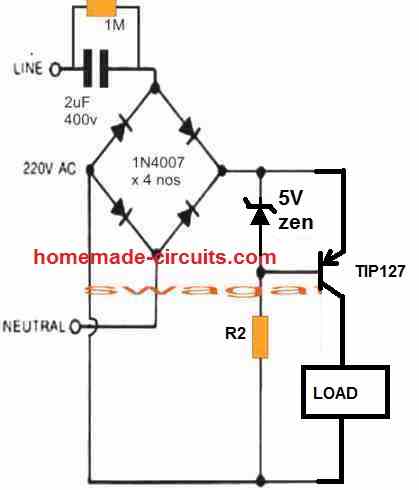
You can adjust the 5V zener value appropriately to get any other zero crossing based output voltage
Good day Swagatam,
I really appreciate all your teachings. Please, I am building a meter using Arduino and I need to power design with AC power. Which of the transformerless can I use to power my circuit because I want it to be compact.
Thanks Joseph, Arduino designs being sensitive electronics must never be used with non-isolated transformerless power supplies, so none of the above should be tried, you should go for a good quality SMPS instead
Thank you Swagatam. i am also trying to get an arduino nano project on a PCB. Do you have any advice or tutorial on SMPS? I am using Fritzing in my design
Hi Nathan, you can try applying the following SMPS concept for powering your Arduino
220V SMPS Cell Phone Charger Circuit
Dear Sir,
I am still newbie in this world of electronics even though I have studied it for 1 semester at university 40 years ago. I tried the circuit based on the first example of your diagram using a diode bridge ic and a 5 volt zener diode. It works for 0.5 watt LEDs, also for 1 watt. when I enlarge C1 to 1.5 uf, resistor R2 geting hot (about 50 degrees Celsius) even though I replace the resistor with 2 watts. Is there any other way than to replace the resistor with a larger wattage?
Thank you and best regards
Dear Maulyani, The R2 will become warm since it has to handle a significant range of current at 310V. The only way to correct is by adding 3 or 4 resistors in series to make an equivalent 50 Ohm, or use an NTC thermistor rated at 30 ohm 1 amp. Any of these options should solve the issue.
Thank you for your attention and suggestion
Best regards
Very usefull & simply explained… Thanks
this topic is “simple …power supply”
the first capacitor solution is simple. the others are not so simple. just upgrades to the capacitor version but the schematic gets so complicated that it ruins the beauty of the solution, you might want considering another approach
The bottom circuits have more features and therefore they have more stages!
Hi Swagatam,
Want to power a 2.4GHz RF module and a mcu with relay controls from either a Transformerless AC-DC Power Supply Circuit as described here or use Meanwell PCB power module IRM-03-5S (AC-DC Single Output Encapsulated power supply, SMD; Input range 85-305VAC; Output 5VDC at 0.6A). Which would you prefer? Will the PCB power module cause any interference in RF module?
Hi Asif, I think the mentioned module should work fine, since these have good EMI filters around the buck converter for eliminating interference. You can give it a try.
Dear Sir,
Although I love building electronic circuits, my problem is getting good components that are going to work. I have purchased many Cs, Rs, Chips and transistors etc in the past, a lot of which don’t work eg: 1k 1% resistor which when tested had a job to reach 800 ohms, well out of spec. Although your circuits look as though they will work, I cannot afford to keep buying duff components which is probably the reason why others have trouble getting their gadgets etc to work. I am in the process of joining Radio-Spares so that I can build your PSUs. You only need one component to be faulty, to make you think a circuit is useless. I will get back to you when I get some decent parts. Many thanks for your circuits.
Dear Harry, thanks for your feedback, I hope you get the good parts soon for building the projects from this site!
Can you tell me what’s the value of the inductor can be used in the circuit “Upgrading to Voltage Stabilized Transformerless Power Supply”,So it will be easier to find one?
The value will need to be experimented a bit, but according to me a 100 turn over any iron core should be enough to block the initial current surge….you can also try increasing it to 200 turns and see the effect.
Sir. Im using this power supply .but C1 ac capacitor is burning continues. Kindly help me.
Suresh, did you use a 400V capacitor? if still it is burning, then either your input supply peak is over 400 V which can be impossible, or the capacitor quality you are using is bad or faulty
For connecting 65 x 3V LED and a 0.33 uF capacitor, you said the supplied current was around 17 mA. My rough calculation is around 10 mA. I guess you might forget the 65 x 3V = 195V LED voltage drop that must be subtracted from the peak voltage to correctly calculating the output current. Remember the less the number of LED connected, the higher is the output current.
What you are saying is wrong. The LED specification is 20 mA so my 17 mA is absolutely correct. When you add LED in series, the voltage across it will change, not the current, the current will remain the same through the entire string. How will 10mA be sufficient for a 20 mA LED string????
Greetings, I haven’t been here so long just getting back into this type of electronics.
I like the 555 version but like I saw in an earlier example why don’t you have a resistor or Ntc or the neutral Ac phase going in?
Also I would love to build this but I would just need maximum current out and I would just need the circuit to delay for the zero crossing only once when it is turning on just like using the opto isolator triacs, so I would assume I could remove the 1M preset with a 1M resistor?
Welcome back to homemade circuits.
Yes the 555 version appares to be a foolproof design
For using the zero crossing feature only at the start, you may have to convert the IC into a set/reset configuration.
Here, the pin7 can be kept open, pin6 connected to the ground via a 10k resistor, and remove all the existing parts which are shown connected to pin6/7 in the above diagram.
hi,this is nandhu i want to power circuit in 2A and transformer less power supply circuit.also i want variable output with same circuit.this is possible to make????
It is possible to build a 2 amp using the MOSFET control design, however one drawback of the circuit is that the transistor can get significantly hot in this design.
Okay thanks you, I want variable switching mode power supply circuit please help me.+12-0-12 1A output circuit I needed.
sorry, I do not have a variable SMPS design with me right now!
I want to single power supply but positive and negative output in same variable adjustment circuit. Pls any idea
You can refer to the examples provided in the following article:
Adjustable 3V, 5V, 6V, 9V,12V,15V Dual Power Supply Circuit
I want one doubt sir, I want 12-0-12 power supply as well as I need add next 13volt also its possible to make pls give me any ideas.
Nandhu, sorry I did not understand your question, do you want a 12V and 24V power supply combined?
Yea sir, I want +12-0-12 power supply at same time,I need adjust 0-24v using same circuit. Its is possible??
Nandhu, You can refer to the previous link which I suggested you. When you adjust the power supply to +12-0-12V, the +/- outer two wires will give you 0-24V.
I made the 1) Basic Transformerless Design and it worked but I used it to power an arduino. The issue that I have is that I wanted to measure the ac voltage so I placed a voltage divider at the end of the circuit but varying the ac hardly makes a change to the dc voltage output.
After checking the output from the capacitor I get 16vAC I included the resistor on the other phase which limits the voltage to approximately 9v before its rectified.
How can I do a simple setup to measure with the arduino and its a small circuit I dont want to use a transformer.
A capacitive power supply is strictly not recommended for Arduino, you must use an SMPS adapter.
In the explained transformerless power supply circuit, if you remove the zener diode and the filter capacitor you should be able to measure the full 300 V DC after the bridge rectifier, and 220V after the mains input capacitor.
Hi Swagatam,
I am looking for a 12V 300mA transformerless power supply, How can I change your power supply unit.
Thanks
Pradeep
Hi Pradeep, 300 mA is quite a large current for a capacitive power supply. Still, you can probably try the following design, and see if it works:
Make sure to replace the 105 capacitor with a 7uF/400V capacitor
hi sir.
if assume this takes (1uf/400v) 100mA, 230v*0.1A = 23W
23 will be a initial input wattage.
and as comment above some said output has around 40v without zenor.
if i use 12v , 12v*0.1A =1.2W
or 40V*0.1mA = 4W
what happens to the others.. they all will waste? or am i wrong.
could you please explain this. what is the most efficient way. this method or using a transformer (12v 500mA or 1A)..
thank you..
Hi panchala,
without a zener diode, the output from the bridge rectifier will 310V. If a zener diode is connected, then the voltage will stabilize to the zener value, and the remaining power will be wasted. Using a transformer or an SMPS is the most efficient way of making a power supply.
hello sir..
thank you for the reply.
this is all about build a units which i need to power 5630 or 2835 SMD LEDs (using 20-60pcs ).
i got some transformers extracted from UPS
1.)can i use that LED Decoration Light Application circuit for series the LEDs
2.)or still a transformer will be a efficient way ?
thank you for the advice.
Hell panchala,
you can definitely use the decoration application circuit above, but you will have to add a 5 watt zener after the bridge. The zener voltage value should be equal to the total forward drop of the series LED circuit.
thank you sir..
wont this work without zenor?
i think that one has a 220v and 50mA out.
so i can series 220/3.6 or 220/9 LEDs am i right sir
Even though it is only 50 ma, still without a high watt zener the LEDs can burn quickly, anytime, especially during power switch ON periods. It can very unpredictable and unreliable.
You can divide the peak DC voltage which can be 310V, with the LED voltage, to get the total number of LEDs in series
ok sir. thanks for all..
and happy innovations..:))
You are most welcome panchala….
Kindly explain how you calculate the value of R2 and C2 in your transformerless power supply circuit
R2 can be difficult to calculate, because it is used for protecting the zener diode from initial surge current which can be very high, but only for a few microseconds. Therefore R2 can be anything between 10 ohm and 50 ohm, or it can be replaced with a 10 ohm NTC.
C2 can be calculated as explained in the following article:
Calculating Filter Capacitor for Smoothing Ripple
Good morning sir. I have a problem. For the power supply with the ne555 which controls the thyristor, if my led can draw a current of 1A, I must use a 10 / 400V capacitor? and if I don’t put this capacitor and also the 1M resistor, the thyristor cannot limit the current in the led by varying the signal to that gate?
Hello Daoud, for 1 amp current you will have to use a 20uF/400V capacitor. Without this capacitor the SCR and the LED will burn instantly. Even with the 20uF the LED can burn if a limiting resistor is not used with the LED
Hello Swagatham, I’m an avid follower of most of your articles. I have read all about transformerless power supplies and made two to power PIC microcontroller. I faced a problem in controlling TRIAC in same circuit from the Microcontroller. Will send the circuit later. Right now my question is bit unusual: The Higher uF CBB capacitors cost more especially 2uFand 5uF, if i want more output current in Transformerless power supply (50mA/uF as you said). An interesting possibility is to use Cheaper Aluminum electrolytic capacitors, say 4.7uF/400V ? Of course we cant use in AC directly but can we place it AFTER the 1KV bridge rectifer? since its output is Pulsating DC, we can place the electrolytic cap after the Bridge and utilize it to reduce the input voltage ? Would that be safe for the electrolytic, since they are self-repairing as long as polarity is not reversed. Please answer my doubt.
Thank you A.Raj,
I wouldn’t recommend a capacitive power supply for a microcontroller since these are not isolated from the AC mains. An SMPS is perhaps the ideal choice for any electronic circuit today.
The biggest problem with capacitive power supplies is the surge current during power switch ON, and the high peak voltage which is always equal to the AC input unless a suitable zener diode is used to control it. Using zener diode on the other hand results in wastage of power.
Even if you connect the capacitor after the bridge rectifier still it would not prevent the above explained problems of high voltage and high switch ON surge current…so according to me it is not advisable to use capacitive power supplies for sensitive electronic circuits.
Hello Swagatham, I just found you blog and I am fascinated about the variety of your articles.
I have 2 questions regarding all the transformerless circuits above:
1. Why not adding a capacitor on both ends of the mains so we HAVE a complete insulation (apart from the 1M ohm resistor on both C)?
2. Why not adding a inductor in series to C1 to avoid the inrush current (of course the resonance frequency with C1 should then be fairly high compared to the mains frequency so that there won’t be any oscillator)?
BR Phu
Thank you very much Phu, I appreciate your thoughts!
Adding capacitors on both the inputs will cause the current to become less by 50% and this won’t make the circuit isolated from mains, since even 10mA current from the capacitor may be quite sufficient to kill a living being.
An inductor in series can help to restrict current surge, I have already tried to implement this in the following concept, however, it is still not a fail-proof idea and this will not guarantee a 100% safety to the attached electronics, from mains surge.
https://www.homemade-circuits.com/make-1-watt-led-lamp-using-20ma-leds/
On the contrary, a zener diode makes sure that the current and voltage can never rise beyond the rated value of the zener thus allowing total safety to the attached electronics.
Hi Swagatam
Thanks for pointing that out, indeed you made me realize the basics!
Galvanic separation with capacitor is only possible for DC! (I usually tinker with less than 10V)
And thanks for your incredible fast answer!
Of course I was assuming that the value of the caps need to be doubled to keep the current. But still, it would bring the voltage potential up to somewhat half of the hot wire in relation to neutral/ground.
The conclusion is as you do repeat: there is no way around, transformerless on mains remains dangerous and must not be touched unless one can guarantee that the mains wires can not be interchanged (and that the neutral potential is close to earth).
I agree with a commenter from France above: there is usually no guarantee that hot and neutral are connected correctly, half of the times they will be exchanged and the output will be floating around the hot wire potential.
Best regards and thanks for the inspiration. Phu
You are welcome Phu, I appreciate your understanding. All your assumptions are correct and makes sense!
Thanks Mrs Swagatam, we really appreciate your efforts on helping us with a lot of information regarding to circuits and a lot more.
Please my questions goes this way, how can I will explain to design our own circuits while having the idea. Meaning to know what components, their value and many more to be use, for example let say I’m to build a power bank Circuit, how can I set down and draw it and knowing the components to be use without looking at someone’s circuit. I already knew the working principles of basic components, such as Resistor, capacitor, Inductor etc. Your answer I’m sure will help a lot of Electrical and Electronics students.
Here Is my email (hskgwale@gmail.com) sir, are will like to be contacted when the answer is provided.
Thank you!
Thank you Hassan, designing electronic circuit requires the knowledge across multiple areas of electronics, which can be achieved only through relentless studying of electronic circuits and practical experimentation, it cannot explained through comments. You have to first learn and grasp small transistorized circuit modules, and IC modules. Once you have mastered it then you can build bigger projects by joining several of these circuit modules.
Power banks are of many types, one with only batteries, and one with a boost converters, so you will have to learn how boost converters work, and cell phone charging specifications to ensure it accepts the charge from your circuit.
Thank you sir for your kind answer.
Hello sir,
I upgraded the basic transformer-less power supply to get 24V, 200mA replacing
Z1 with 24V, 1W (1N4749),
C1 with 3.2μF (I used 2.2μF and 1.0μF in parallel),
C2 with 1000μF 50V
R2 with 5Ω 2W
My intention is to power a DC fan rated at 24V, 200mA (4.8W) with variable voltage control to control fan speed.
I used a basic circuit with IRFZ44N MOSFET and 10K Potentiometer to achieve voltage control
But, the problem is Zener diode is producing lot of heat when the fan is running at low voltages.
When the fan is running at maximum voltage circuit works fine and there is no problems with the Z1 (i.e., fan is consuming full current running through the circuit)
What I think is to place five 24V 1W Zener diodes to get 5W rating and avoid Zener diode getting burned.
My question is,
Are there better ways to pass the current that is not consumed by the fan and protect Zener diode and to control speed of my fan?
I really want a transformer-less method to power my fan.
Thanks in advance!
Hello Lisitha, which circuit are you using to control the speed of the motor? Is it a PWM method, or linear transistor method?
But anyway, a good option is to replace the zener diode with a transistorized/zener circuit as shown below.
R1 can be 1K 1 watt, VR1 can be a 4k7 pot, T1 can be a TIP122 transistor.
If you want to put 5 zeners in parallel, you can do that, but make sure to put a small value resistor in series with each zener. You can put a 10 ohm 1/4 watt resistor in series with each of the zener diodes.
Sir,
I used a linear transistor method to control fan speed.
Now I tested your transistor-zener circuit and 1K resistor and zener diode instantaneously got burned at a lower voltage.
I’m not sure about that R1 resistor value.
Lisitha, the zener is protected by R1, which can be a 1K resistor, so the zener can never burn.
Did you apply the required protections across the motor. for example a reverse diode and a capacitor? If you don’t put a capacitor and a diode across the motor, its back EMF may damage the transistor and the zener.
Good Day Sir,
Thanks very much for this wonderful article on transformerless power supply.I have been trying to use it repair some damaged China torches all to no avail.Thank God for your web,i will try the above.
But my question is. why not incorporate the high voltage capacitor and discharging resistor on the other line,presumably neutral, because AC flows in both directions alternately.This issue of positive and negative in AC network confuses me.Please can you help.
There is one i built,it glows and later stops working.
Please label your diagrams so one can make better reference. Thank you.
Thank you Patrick, Glad you found the article useful.
The capacitor is responsible for limiting the input high current to the desired lower levels at the output, so just a single capacitor in series with any of the AC supply inputs is enough for the purpose. The value of the capacitor is directly proportional to the output current reduction level. If you connect two capacitors across the two AC inputs, then the two capacitor would get connected in series causing the effective current to reduce by 50%. Meaning if we use two 1uF/400V capacitors are connected across the two inputs, the effective capacitance would become 0.5uF/400V, reducing the output current by 50% than the required value.
Moreover, adding two capacitors across the two inputs would actually do nothing or improve nothing in the design.
This Muthu From Bangalore .
Looking technical advice to resolve Cap drop power supply Current limiting resistor ( Ref R4 = 22E/2w ) burning issue in the field .
Attached the Cap drop power supply schematic which we are using to power up the MCU . We made Lab test and 4Kv surge test , didn’t find any issue . But we are getting rejection from field and noticed most of the PCB this current limiting resistors are burnt.
Could you please suggest what’s the wrong in our schematic and how to resolve this issue .
Looking for your reply .
Hello Muthu, I saw your diagram in my email, however I found it quite confusing. But I can tell you why the 22 ohm resistor is burning. It is due to the initial current surge which the resistor is unable to handle. To prevent this you will have decrease the value of the 22 ohm to may be 5 ohms 2 watt, and increase the wattage of the 5 V zener to 2 watt or 5 watt.
You can also consider using a transistorized stabilizer as shown in the second diagram from top, in the above article.
Hello Swagatam,
Thanks for your quick reply . I didn’t expected this , really i’m very happy .
Coming to my diagram, i’m using this cap drop supply to power up MCU , and i want to trigger the TRIAC in Q2 & Q3 quadrant (negative gate triggering ) ,that’s why i made the diagram like that.
In 5V output the max load current is 5-10mA . In this the NTC won’t help to limit the initial surge current , so i used this 22E/2w wire wound 2.5kv surge withstand resistor.
With ref. your suggestion i will change this value to 4.7E/2W , I believe this will solve this resistor burning issue .
Thanks/regards
Muthu
You are welcome Muthu, yes you can try 4.7E/2W along with a 5 V 5 watt zener diode and check the results….hope it will do the job.
Please can the above method be used for a load of 1000watts dc coil
No, it cannot be used for high power loads.
Ok thanks. Please can you give me the schematic of high power load
What is the voltage rating of your load?
240vdc, 1000watts
If its 240 V then why do you need a transformerless power supply? You can power it directly from the mains source.
Hi Swagatham
Was going through these circuits and I want to know if the first circuit in this Article or the second one with the transistor is good for powering a 5 volt time delayed relay circuit for a timer for an exhaust fan direct from 125 volts mains supply
Awaiting your reply
Thanks Swagatham
Hi Val,
yes you can use the first or the third circuit to operate a 5V relay delay circuit with some modifications. You will have to replace the R2 resistor with a 5 ohm 2 watt resistor, or even better to replace it with a 5 ohm NTC thermistor. And also the zener diode will need to be replaced with a 12V 2 watt or 5 watt zener, because a 1 watt zener diode may not be able to handle 50 mA current from the 105 capacitor and could burn. There can be one issue which I am not sure of. It is when the relay switches ON, it will draw a significant amount of current which might disturb the working of the electronic delay timer operation. Whether this issue can happen or not can be confirmed only by building the circuit practically.
Hello sir, first of all thanks alot for for sharing this much of huge information on transformerless powersupplies sir I have few questions regarding these powersupplies i am using transformerless powersupplies in my products for past 3 years And I am facing some issue hope you might help first of all my product consists of some mcu and leds and it works on 3.3-5V and consumes current about 20mA
1. First issue which I commonly found is if someone uses inverter its R2 resistor got damaged got burnt dont I have also tested many transformerless powersupply product on inverter (Both square wave type and sine wave type ) so most of the R2 burn cases i got from people who have an inverter .(I am using 684J capacitor & 10ohm resistor As R2 )
2. Another issue is in some cases this resistor got very hot even without an inverter and in most cases around 98% it wont create any issue or heating problem i dont understand why
3. Also I have tried on more thing to protect my circuit i have removed R2 by shorting it directly and Connected 10Ohm resistor in series between C2 and load this actually reduces 5v to 4.5Volts and also results in loss of current but for my circuit it works fine because i dont need much current and voltage and after applying this I have tried frequent on and off tests and it withstands my load remains intact also i have tested this on square wave type inverter it works without any issue didnt noticed any heat or rise in temperature so i just wanna know that can this solution can be used for long run .
4. Also can you please suggest a simple way to test our tranformer less powersupply that it can withstand inrush current or not .
Thanks alot in Advance Sir
Akshay Jha
Thank you Akshay,
R2 being in series with the input has to tolerate the total inrush current and that is why it is always prone to burning. The solution is to use a low value high watt resistor for the R2 so that it blocks the in rush current to some extent and does not have to block a vast amount of current across it. For example you can use a 3 ohm 2 watt resistor for R2, and another 10 ohm 1 watt resistor after the bridge rectifier. The better option is to use a 5 ohm NTC which will initially block the entire surge current and then slowly allow the full current as it warms up. So you can also replace R2 with an NTC. Also make sure that if resistors are used they are wire wound type and not carbon type.
If you are finding the limiting resistor cooler after C2, then it is a good thing, you can place it there but the correct position is after the bridge rectifier where it can protect the zener diode also.
The most important element in the circuit is the zener diode which alone can do both the jobs together. It can suppress excess current and voltage both. However in the process it can get itself burned therefore it must be a high wattage type zener.
For 20 mA current 684 capacitor is very high. You must use a 0.33uF or a 0.47uF capacitor which will provide the exact 20 ma current and that will help to keep the limiting resistors cooler.
It is difficult to calculate the R2 value because the surge current is never uniform, that is why it is a good idea to use an NTC instead, which will protect all types of surge current initially and then revert to normal after a couple of seconds to allow the full rated current to the load.
Thanks alot for quick response and for all your suggestions I am definately gonna use 5 ohm NTC as R2 .also is it possible to test your circuit for surges that i asked any simple way to test your circuit properly that it is able yo withstand surge currents or not if you can share that that would be really helpful because testing our product directly in market is not good if we can do proper testing it would be really great and its would be really helpful
Thanks alot for your time help its really amazing to have suggestion from you
You are welcome Akshay! The only way to test the surge control is by switching the circuit ON/OFF randomly as many times as possible, or a few times every after 1 hour. Or you an make a relay ON/OFF circuit and power your transformerless circuit through the relay to switch it ON/OFF continuously as many times as required.
For example you can attach two transfomerless power supply circuits with the relay of the following circuit for the mentioned ON/OFF switching test.
https://www.homemade-circuits.com/alternate-switching-relay-timer-circuit/
Hi, Swagatam!!!
I tried a circuit with a 13003 transistor to connect a load with a current of no more than 100 milliamps.
When Zenner diode is turned on at 5 volts, the output is 8 volts and current is about 40 milliamps. The transistor gets very very hot!
If I change the Zenner diode to 6.8 volts, we get 10 volts at the output, and the load current increases to 50-55 milliamps, the transistor heats up less.
For my needs at the moment 12 volts is OK, so I turned on the 10 volt diode, got 13 volts, the current at the load is 75 milliamps, transistor is hot, but the finger can withstand its temperature.
Questions:
1. Why does the transistor heat up at low voltage and low current, and when the voltage increases, the current also increases, but the heating of the transistor decreases significantly?
2. How to prevent strong heating of 13003 at a voltage of 5-9 volts?
Hi Jorge,
Thank for building the circuit and providing the results here!
The transistor is getting hot due to the input/output voltage difference. The input voltage is 230V, while the output is only 5 to 12V, therefore the transistor has to dissipate the excess wattage through heat.
Unfortunately there’s no way to control this heat, unless you build an SMPS circuit.
In the above circuit there is no explanation about D5 1N4007 diode. Please explain.
D5 is actually not required, you can remove it if you want.
zener diode has no current limiting resistance how will it operate and what is the function of D5
R2 and R3 are the current the limiter resistors. D5 is optional, it blocks all discharge paths of C2 except the load.
If I want to design transformer less for 1500 watts microwave from 220 v/110v
Hello Swagatam! Love your circuits! I have been simulating your transformerless designs and they are beautiful. Thank you for sharing your knowledge. Looking forward to diving deeper into your site.
It’s my pleasure Lowell! glad you found the posts helpful…wish you all the best!
Hi Mr Swag
I really appreciate your effort in tutoring people about Electronics so my question is about the transformerless power supply with limiting capacitor how can one integrate an LED in it and also use an electrolytic capacitor to reduce it output voltage. Why I asked is because most rechargeable lamp I come across use this circuit. thanks
Hi Isiaka,
The high voltage input capacitor reduces current and the zener diode reduces the voltage. Please specify the voltage and current rating of your LED and how many of them would you like to incorporate? I will try to figure it out for you!
Hi your article is areat, may i have some advice for my university miniproject please?
The project goal ; Power supply 220VAC to 15VDC 3-5A
At first my condition to made this project a power supply without transformer because its quite expensive tranformer with 3-5A so i decided to use your Transformerless circuit. My first try i used zener 2.2uF(225j/400V) with R 1M then converter to dc with diode (4 x 1N4007) then pararalle with 15V zener diode and 470uF capacitor. so its gave me 15VDC but the current its just 0.01A then i think its cause from the diode bridge. so i changed diode with the bigger one then its not work again..
So the question is which component that i need to change to get 3-5A with 15VDC?
#Thankyou for your advice
Hi, thanks for your question.
Capacitive power supply circuits as explained above are simply not recommended for currents above 200 mA. For 3 amp or 5 amp you can go for an SMPS topology.
If you try anything above 200 mA using capacitive power supply, the circuit will get hugely inefficient and dangerous for the load and also for the zener diode, transistors etc. Also there will a lot of heat generated from the mosfet or transistor used to regulate the output DC.
You can add 3 polypropylene capacitor in parallel to add the current
Swagatam,
thanks for this most valuable information.
I could use a hand on a small “project”. I know that powering microcontrollers with this kind of supply is far from ideal, but I’d like to give it a try.
I do have several of these RF-433 Mhz sockets that are probably 20 years old by now, but still work well. The switches of the remotes are not working well anymore but I have decoded all of their RF-Signals and managed to control them from an arduino or an esp via RF422 sender modules. So I could extend the sockets’ life span if the remotes quit their job.
What I don’t like about this technology is that You have no feedback – so You never know if the switching worked unless it is a lamp within sight – and the remote can only be as remote as the rf-signal goes.
So for years my idea is to extend these sockets with an esp and their enclosure actually offers enough room for an esp-01 even with the pins and dupont connectors.
I have found a point where a nice 3.6V signal – actually quite smooth – is handed over to the rf part as well as points to trigger the switching and read the state.
However, the circuit is not designed to support additional load and the esp draws up to 170mA especially during boot up.
So my idea is to maybe use some of the given infrastructure but divert to a second route at a certain point to power the esp.
I’d like to send You pictures of the pcb as they seem to follow an interesting approach. I have not fully reverse engineered it (as if I could) but appart from two blobs for the rf and the programming/switching stuff on the low voltage side there are no ics and they don’t even seem to use a full rectification.
On the live side there is just one diode 1N4004 followed by a big 22k resistor (2 watts?) and a bzx 55c zener diode. The rest consists of a few throughmount electrolytic caps (10V, 16V, 63V, so already on the low power side), smd caps, resistors and transistors (L6).
there is a second 1N4004 on the coil side of the relay, but I guess that is just reverse spike protection. the circuit drives a 48V DC relay with 16A/240V, so quite beafy for this kind of toy application.
I guess one could start a second power supply route after the resistor or the zener, but I would not know how to properly follow that route.
Would be great If, with Your help, I could make this work.
… I actually posted an image of the back side of the pcb in a github discussion about the protocol a few years ago:
https://github.com/sui77/rc-switch/issues/231#issuecomment-390038300
the front side just has the relay, 22k resistor, 2 1N4004s, zener and the tmt-caps on it. no additional components.
Thanks!
Kind regards
Frank
Thank you Frank, I appreciate your question!
As far as I have understood, you want to power the ESP through an external transformerless power supply.
However, it can be quite difficult for me to suggest a proper way of implementing it just by looking at the given PCB layout. If the circuit is in a schematic format then probably we can trace out a suitable way to solve the problem.
If you have any further suggestions, please let me know I will try my best to sort it out.
Hello Swagatam,
thanks for the quick response.
>> …As far as I have understood, you want to power the ESP through an external transformerless power supply. <<
Actually no. Sorry, if I did not make that clear. My first idea was to attach the ESP to the existing circuit, as it already creates a quite nice 3.6V supply for the 433Mhz RF-part and the second blob. However, the circuit is obviously not able to deliver the additional mA required to drive the ESP. I've tried it and can actually power the ESP-01 board (red LED workiing), but as soon as I engage the chip_enable pin, the rest of the board is not working properly anymore and the ESP does not boot. So it is just drawing too much current. The power supply simply was not designed for that.
So my idea was to maybe pick up power after the zener, where it already is cut down to ~50V and build something from there or from any other place that is suitable to get the desired max of 170mA.
I could directly start from live and neutral and try to employ one of Your designs, but that would require components and thus space in the enclosure. So my idea was to make use of something that is already there. I was hoping You could easily see what is going on as the design is open and clear. I am lacking the expertise to fully understand the flow.
I could try to draw a shematic from what I can identify. Just the smd caps are not marked.
Another approach could be to use one of these Hi-Link Modules (HLK-PM03), but appart from being too big for the given enclosure I'd then be isolated from mains, which probably would require opto-couplers or so for switching and state reading.
Frank
Thank you Frank,
I think I have understood now.
I can suggest you a suitable design which could be integrated after the 50 V source. The circuit would be an emitter follower transistor with its base voltage suitably clamped to the desired output voltage using a resistive divider, and for boosting current, the collector of the transistor would be connected to the 220 V source via a limiting capacitor.
Let me know your thoughts on this.
Swagatam,
that is exactely what my intension was. I just have no idea how to achieve it.
If my idea is a good one, we will see.
If You can give me more information, I’ll try to get the components and see if I can get the ESP powered parallel to the current function.
Thanks in advance
Frank
I think my previous idea is not a good one, since it would create a lot of heat and also would be quite bulky.
If you are sure of the 50 V DC source from the board then you can optimize it for getting higher current using the following design which is very efficient, and perfectly suited to your application.
Please try the last design provided in the following article:
https://www.homemade-circuits.com/0-to-50-v-adjustable-switching-power-supply-circuit-using-ic-lm2576/
Hmm.. yes. That is probably the best idea (ever). Especially as the voltage drops down below 20V when the relay coil draws power.
I will re-check the voltages and if I can get reliable values.
Instead of the LM2576-HVT-adj I could probably use the LM2575-HVT-5.0 (or its -HVS variant) and place an AMS1117 behind it in order to get down to 3.3V. The LM2575 has an output of up to 1A, which should be sufficient. Maybe I’ll find a suitable buck converter module in my boxes. That would surely be too bulky but serve for a proof of concept.
I’d still like to understand how the voltage regulation of the socket’s pcb actually works, as it seems to be so different from the “standard” rectification approach….
Thanks so far for pointing me into this direction. I will keep You updated of my findings. Even if this might take a few days or weeks.
Kind regards
Frank
Yes, that seems to be a good idea, using the 5 V version and then using a 3.3 V regulator to finally get the optimized 3.3 V output at higher current.
Instead of the LM2576 if you can find a smaller buck converter that would also do the job perfectly.
I could have tried figuring out the working of the board if a schematic would be available.
All the best to you!
Merry Christmas to all of You – thank You, Swagatam,
>> I could have tried figuring out the working of the board if a schematic would be available. <> Instead of the LM2576 if you can find a smaller buck converter that would also do the job perfectly. <<
I have found a buck converter in my boxes that is actually using the LM2596. Not the HV-version though, so just rated up to 40 V. But the LM2596 data sheet allows for a max of 45V and as I never saw more than 43.something volts, I thought I could give it a try – just for testing.
No luck though. With the buck converter attached, neither of the components work.
Nothing gets damaged, as both work fine again independently after separation, but it seems that even the buck converter ist drawing too much power. 🙁
… Yes. For a test, I've attached the buck converter parallel to the the relay coil. When switched on, it lights up just for a fraction of a second not leaving enough for the relay to "click".
I'm surprised how little it takes to satisfiy a relay coil. I expected it to be a lot more hungry.
It seems, I'll have to find a completely different solution, if I want to make this work.
Maybe, I could modify the given circuit so that it provides more current?
Best
Frank
Merry Christmas to you too!
Buck converters are usually very efficient, upto 80 to 90%, so it is strange it is drawing a high current. But yes a relay at 50 V would require hardly 5 mA to 10 ma current to operate which can be of course very less for a buck converter to operate optimally.
Let me know if you have any further queries, I will try to figure out a solution, if possible.
Swagatam,
I just saw that the comment function swallowed parts of my post. Especially the link to the circuit. It obviously did not like my quoting. The text was:
Out of curiosity I followed the traces and put down the schematic. That was tedious, but if I did not completely mess it up, this should be it:
https://www.personalplanung.com/specials/swagatam_20221226/RS_200_Schaltplan.pdf
As it was of no interest, I left out the RF-433 section that is clearly seperated from the rest.
—-
The buck converter I used also has a 3-digit LED-Display which might be the cause. However, if this can’t be handled, it would not be enough for the ESP anyway. Hopefully the schematic will tell You more.
The current available seems to be calculated to be just “on the edge”. Its a 48V relay, but it only gets something like 43 V. When switched on, the Voltage drops down to 18V. Just enough to hold the relay engaged.
Is the Zener the limiting factor? The BZX55C43 just has 0.5W. I could try to replace it with a BZX85C43 which has a rating of 1.3W. Or would that blow up other components?
I started this with the idea of being an interesting afternoon project. But as with most projects things often are not as simple as they appear. Unfortunately I am now keeping You busy, which I am sorry for. I am grateful for Your support, but please simply tell me, if I’m asking too much. In the end it’s my project and not Yours.
Thanks!
Frank
Hello Frank,
You must remove the LED display from the buck converter and check again.
I checked your circuit diagram. It seems the R1 and the zener diode D3 are the ones that are significantly limiting the current and voltage respectively.
You can reduce the R1 value to 10K 5 watts and increase the zener value from 43V to 60 V and check the response.
The 48V relay will safely work with 60 V also since the current will be still quite low with a 10K for R1.
However, R1 might heat up a lot, even 22K would heat up a lot, so if that’s a problem then I think you must replace the R2 with a capacitor with a value of 1uF/400V that would provide sufficient current for your relay as well as for the buck converter to operate correctly.
If you have any further questions please let me know.
Hello Swagatam,
Thanks, yes the 22k resistor obviously gets hot. I’ve opened several of them and all of them have the pcb “burned” around the resistor. Definitely not the most effective way.
I’ll try out the different approaches and report my findings. Guess, I’ll take the capacitor way. This will take some time, as I have to order the parts first and my buck converter will not work with 60V. So I have to get the LM2575-HVx and stuff as well.
I actually do have one of these sockets where the resistor is blown up as well as the RF blob. I’ll check if I can use this one as a test dummy.
’til then – stay well !
Frank
Thank you Frank,
No problem! Let us know how it goes. I hope you will be able to solve the issue soon. Feel free to reply back if you have any further doubts or questions.
Hallo Swagatam,
I have some old “quite” smart multiplugs that doesn’t work.
I called it quite smart because their only function is to switch-off the multi plug when detects that the tv is in stand-by mode.
I prepared some photos of this appliances and prepare also a complete schematic, and for this question, a simplyfied schema of powes section
because the zener diode is damages. It is a SMD package so it is difficult for me to identify the right value.
May you help me to chose the right value for this zenere diode?
Thanks in advance for your help.
This is the link for the photos
https://we.tl/t-IArWl9Lqez
I hope I posted my question in the right place, otherwise I’m sorry for my choice
CDN
Hello Claudio,
Are you referring to the zener diode Z1?
Yes, the actual zener diode doesen’t work…
Thanks in advance.
As you can see there’s no proper resistor to protect this zener diode. The only resistor which is trying to protect the zener diode is the NTC which has hardly 5 or 10 ohms when it has normalized, which can be too less for the zener diode.
I would recommend connecting a 100 ohm 2 watt resistor in series with the NTC which will make sure that the zener never burns.
Or alternatively, you can replace the zener diode with a 3 watt or 5 watt zener diode.
Thanks a lot for your answer. My most important issue is to define the zener value. Can you help me considering my “tension reading test” with an other working device? The circuit work with a 78L05 so, in your opinion what is the actual zener value? Thanks for your cooperation.
You are welcome! The actual zener value can be anything below 30 V and above 9 V, which is safe for the 78L05.
I am sorry I do not have an alternative circuit design for this.
Thanks a lot but what value do you suggest? What is the better value for the input tension of 78L05?
Thanks in advance
Claudio
You can use a 12V zener for getting 5V from the 78L05
Dear Swagatam,
thanks for this usefull information. I have a question: I made a voltage measure on the working zener and value is around 25,3 Volt but I expected to read the zener value. After I’ll replace the old zener with a new one 12Volt the tension that I’ll read will be 12Volt?. May be I’m completly wrong but can you solve my doubt?
Hello Claudius, as suggested by me earlier, you can use a 12V zener in your diagram before the 78L05 IC. But remember to add a 100 ohm 2 watt resistor in series with the NTC otherwise the 12V zener diode will also burn.
Hi, Swagatam!!! Your diagram using 2 transistors + has the line voltage connected wrong to the bridge rectifier circuit..
Thank you John Boy, I have corrected the bridge rectifier connections in the second last diagram now.
Hi Mr. Swagatam. Nice to hear about you. I am also an Electrical Engineer. At the moment I am retired. Still my hobby is to try new circuits. Most of the tested circuits are drawn and originated by you. I found most of your circuits are very helpful and happy to work with. Congratulations and I will write to you in future. Thanks.
Thank you Keerthisena, I appreciate your kind words and glad you liked the website. Yes, most of the circuits are designed and drawn by me. Let me know if you have any further questions or doubts.
Hi swagamat I need diagram transformerless power supply use for amplifier engine
Hi Ezekiel, I am not sure what is an amplifier engine. Please elaborate.
Hi Swagatam. Refering to the fourth circuit above where the surge resistor is replaced with an NTC, could you please comment on the purpose of R2 (10-30 ohm), and how to calculate the resistance and wattage? Also does the inclusion of R2 negate the advantage of replacing the surge resistor with an NTC, since it would again limit the available output current?
Hi Peter, R2 is placed solely to protect the zener diode. However if you find that a 5 watt zener has no problems handling the 220V 100 mA supply from the 2uF capacitor then you can remove the resistor. Calculating this resistor can be a bit complex so it is better to determine it through some practical trial and error.
Hello, I made the second circuit which is output controlled by 13003 transistor and 12v zener. I used 1.5uF 400v as C1 but output is 37volts not 12 volts
That means you 12V zener diode could be faulty. Try changing it and check the results. Also check the base/emitter voltage of the transistor, make sure it is 0.7V, that would indicate that it is conducting, otherwise not.
I am trouble shooting a transformer-less power supply. Voltage is low .not sure what component wold cause a low voltage. Thanks
P. POPIEL
Do you have a zener diode in it?
Yes there is a zener diode in the circuit.
Please remove the zener diode and check the voltage again, if there’s any filter capacitor remove that too and check the output voltage.
Hi swatagam. Thank you so much for this article. I need cheap and long lasting life transformerless power supply for my project. I need 50 of this circuit and it needs to be small because there is not enough space in the box. Device is arduino based and it consumes 80-200mA in 5V. Generally 80mA, when the relay activated 150mA and max 200 mA current will be drawn. I want to use the first method, but I think the zener diode will not last long since the current is not constant.
What would you recommend me to do in a way that will take up the least amount of space and cost the lowest? The circuit needs to work for many years? I’m having problems with the calculation and choosing the right components. Thank you in advance.
Hi LIGWD,
I wouldn’t recommned using a transformerless power supply for powering something as sensitive as an Arduino board, moreover using a transformerless power supply would cause the whole Arduino to float with fatal 220V AC.
However if you still insist on trying a transformrmeless power supply circuit, I would suggest you to expermenet with the last design which is a zero crossing protected design. However the transistor should be rated at 400V or above so you may consider replacing the TIP127 with a 400V PNP BJT.
https://www.st.com/content/ccc/resource/technical/document/datasheet/group2/e4/81/3e/37/03/e6/4f/f3/CD00003122/files/CD00003122.pdf/jcr:content/translations/en.CD00003122.pdf
Thanks for your reply swatagam. I don’t need insulation because the whole circuit will be in an isolated plastic box. I want the circuit to be long-lasting so that it is not necessary to disassemble the box again. How long will it last in a circuit made with 400V transistors and can it work without overheating without using a heatsink?
I want to use a similar circuit for 3.3v. I will obtain a more stable voltage by using linear regulators such as AMS1117 in the output. What would you recommend to ensure long-lasting operation without heating problems?
If it is appropriate my project, I would like to use the circuit in the 4th diagram, which has a 30 ohm resistor before the NTC and zener diode. Instead of Z1 there will be a 5.6V zener diode. In this case, if the zener diode and the C1 capacitor at the input have a long life, can I use this circuit for many years for 3.3v by adding AMS1117 to the output?
I don’t know how long the Zener diode and C1 capacitor will last.
Thanks in advance.
Hi LIGWD,
The last circuit is not tested by me but I strongly believe that if it is built correctly using a 400V PNP transistor, it will work. The biggest advantage of the last design is that it is zero crossing controlled and is very compact and power efficient. If a 400V 1 amp transistor is used the transistor might last forever since the circuit is zero crossing controlled. Yes it can work without a heatsink, however if it heats a bit you can upgrade the transistor with a 2 amp transistor.
The 4rth diagram is also very nice, although it is not zero crossing controlled. Nevertheless the 5 watt zener diode ensures that everything runs smoothly. You can use any voltage regulator with this circuit after the 1000uF capacitor.
A 5 watt zener should be able to handle all surge currents from a 2.5uF/400V input capacitor (for 250 ma output), and therefore the output capacitor and the regulator IC and the connected load will be perfectly safeguarded.
Thank you very much Swatagam. Since the +400V +1A PNP transistor is expensive in my country, I can use a 300mA 400V PNP transistor called MPSA94, if appropriate. Peak current can reach around 300mA. Since NPN transistors are more affordable, I would like to make a more reliable circuit using MJE13003, but is it possible to design this circuit as NPN by arranging it?
I want to make a long-lasting circuit. Is it necessary to connect two input capacitors in parallel? If I use the latest scheme, will zener diode 0.5W-1W be enough for long life?
I want to calculate the current that will flow through the Zener and I will select the power accordingly. In the 4th scheme, the zener load will increase when low current is drawn and the zener load will decrease at high current. Therefore, if necessary, I can use an MC34-based buck converter at the output and select the zener voltage around 18v. In this case, much less current is drawn and both the capacitor and the zener last longer.
If there is no problem in terms of life, I am thinking of using the last circuit and adding 1117 to the output. Afterwards, ESP and relay will operate and the current drawn will vary between 80-200mA. If it will be more efficient, I want to add 1117 to the output using the 4th scheme.
It is important for me that it is long-lasting, low-cost and takes up little space. If it will take up less space and last longer, I can forget about the cost and use integrated circuits such as Viper12-22. The most important issue is its longevity. What would you recommend to me? Thanks in advance
Hi LIGWD,
A 300 mA transistor will heat up a lot with a 200 mA load, that is why a 1 amp is recommended. An NPN design might require redesigning of the circuit, I will have to figure it out.
As long as a proper resistor is connected with the zener diode, the zener diode will be safe and long lasting.
I am not sure what a 1117 is I guess it is a voltage regulator, you can add it in both the circuits.
Since the last circuit is zero crossing controlled it is more efficient.
The Viper-22 is also very good but not compact enough.
However, the the transformerless circuits discussed above are long lasting but unsafe due to floating mains AC
Thank you very much for your help swatagam. Technicians in our country say that series-connected capacitors in most devices fail quickly. Since it is difficult to find quality capacitors and high-current, high-voltage PNP transistors, I had to give up on capacitive reactance-based circuits. That’s why I’ll use Viper to ensure longevity, even though it’s more costly. Could you please suggest a small circuit that can be made with Viper12A or 22A?
If I can get 5v output directly with Viper, I can get 3.3v with a linear regulator, but if we cannot get a voltage around 5-6V, I will set it to 12v and have to add an MC34-based DC-DC regulator to get 5v. There will be a linear regulator at the output to prevent ripple. I want to get longer life by using a 3-stage circuit in this way, what do you think, what do you recommend?
Since the circuit will be in a completely closed box, there is no security risk. I don’t want isolation.
For the relay, the Viper output must be around 12V or 5V. I’m open to your advice and suggestions. Thanks in advance.
No problem LIGWD,
I have a specific design which can be perfectly suitable for your application. You can check out the following link:
https://www.homemade-circuits.com/simple-220v-smps-buck-converter-circuit/
Thank you very much for your help swatagam. Unfortunately, I cannot use that circuit either, 3 pin inductors are difficult to find here. The closest ratio coil I could find is sold as 6mH/22mH, there is no other information. The number of windings is also unknown. At the same time, since most of the load I will use in the circuit will be 5V, I think it would not be very efficient to have the feedback circuit on the 12v side.
So I want to make a circuit with only 12V output with Viper. A circuit with 12V 150mA output is sufficient for me. If there is no problem, I can add MC34063 to the 12V output and make a smaller and more efficient circuit without a linear regulator. Normally, I was thinking of using it as Viper-MC34-linear. What do you recommend? Can I make a circuit that works smoothly only with Viper and MC34, will ESP cause problems?
I am experienced with MC34, no problem. Can you share me the smallest, most minimal and cheapest Viper12A/22A circuit? I would be very pleased, thank you in advance.
Hi LIGWD,
The inductor shown in the VipER12 design is supposed to be built manually, it is not available ready made. It has 200 turns and 60 turns of winding over a ferrite drum as indicated in the images. The design has been tested by me thoroughly and it is an excellent circuit by STMicroelectronics. You can make the inductor smaller by using a smaller ferrite core and thinner wires for the winding.
Unfortunately I do not have any other 220V VipER buck converter circuit smaller than this. If I find one will surely let you know.
However, I have another similar design which includes two pin inductors, you can check out the following link, let me know if this looks good.
https://www.homemade-circuits.com/ceiling-led-lamp-driver-circuit/
Hello again Swatagam. I’m sorry that I’m responding so late because I couldn’t deal with the project due to minor health issues 🙁 I examined your LED driver circuit made with Viper and I really liked it, thank you.
I added the same circuit to my design, but instead of giving AC 220V directly to the input, I want to give DC with a bridge diode. Since I am only going to add a single bridge diode, I don’t want to add a rectifier capacitor at the output, unfortunately it takes up a lot of space. Therefore, can I supply AC to the bridge diode and direct the DC voltage at the output to the circuit?
If possible can I remove the 1n4007 and L0 inductor at the input? Can I remove C7, D1, L0, R1, C1 and C2 and replace them with a single 10uF 400V capacitor, leaving R0 at the input for fuse purposes? In this case, it takes up less space, 220V cannot reach the GND output, and it costs less. In short, in addition to the circuit, I want to add a bridge diode to the input and rearrange it.
If adding a bridge diode to the input will not save space, I will give up using a bridge diode.Whatever I can do, I would be very happy if you could help me. Thank you so much, you really helped me a lot.
Thank you LIGWD,
I am not sure whether removing the L0 would cause any harm to the IC or not, but you can try removing it and see how it works.
Bridge rectifier will cause the voltage to increase drastically so I won’t recommend that, instead you can include D1, C1 only at the input side and eliminate the remaining components.
Sir R2 is excessively hot
Musa, please make R2 10 ohms and use a 2 watt zener diode, or try the following concept:

thank you for the information
Please I don’t know the reason My power charger output on inverter is 0.05amps but on generator it is 0.7amps
How are you measuring the current?
Clamp meter, thanks.
If it is happening with the same load then maybe the inverter voltage/power is lower than the generator, which may be causing the difference..
Sir, good evening I have a 12v,10watt filament type bike indicator tiny globe and I want to operate it on an sufficient and safe transformer less circuit.please suggest me and send any safe circuit diagram for it.
Hi Ashu,
You can try the last circuit from the above article.
Use a 6uF/400v for the input capacitor, and 12v zener diode.
Sir, are you talking about the last one with TIP 127 MOSFET?
Yes, the last one with TIP127 BJT.
Sir,
Good evening,
Great article. It is informative with useful links.
Regards,
Thank you Vishwa, Glad you found the circuit useful.
Hi, I have a weir majoreg type441 0-60v, 0-1.5a power supply. Can I, by changing the power transformer and output transistors change the output current up to 10 amps.
Regards and thank you for for all your help to others
You can do that, however the transistor dissipation will be huge at lower output voltages.
Hi,I want to design a power circuit, 220V to 120 VAC, meanwhile 12VDC, then 12VDC to +-15VDC and +5VDC,120VAC is Foating,but the 12VDC is not Floating, how can I finish the isolation?
Hi,you will need an smps circuit for this, however I don’t have a 220v to 120v converter circuit with me right now.
Hello teacher ?
Thank you for your previous answer ???
Sorry my comment was drowned and I had difficulty finding it so I tried to make a new comment ???
There is something I want to ask again with my doubts
, namely:
1. I have followed your instructions to build a power supply with using TIP127 by slightly changing the value of the 33V zener and 10 3V leds and I succeeded, after I measured the ac voltage on the line after C1 it was measured at 30Vac 165mA, the question is whether that means this circuit consumes 30 × 0.165 = 4.95 watts of power ?
2. What is the formula for determining the R2 value in the last circuit that uses the TIP127 transistor?
Thank you ???
Thank you Ulya,
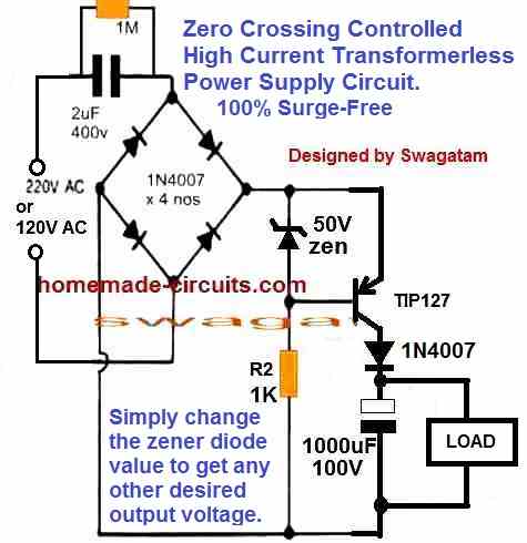
Glad you could build the circuit successfully.
I guess you are referring to the following design:
Yes, i think you calculation is correct, the power consumed is 4.95 watts.
R2 actually can be calculated using the following formula:
R2 = (Supply voltage to transistor base – Transistor base/emitter drop) x transistor hFE / Load current.
In your case, this should be:
R2 = (33 – 1.2) x 1000 / 0.165
R2 = 1,92,727 ohms = 193 k
But the zener diode may not conduct efficiently with a 193k resistor, so it must be reduced appropriately.
Terimakasih guru atas penjelasannya, sekarang saya mengerti
Sekali lagi terimakasih banyak
Semoga kebaikan menyertai anda ???
You are welcome Ulya, Glad I could help!
Hi, please explain the schematic that you built, how did you connect the components, how did you ground the ac…please show the schematic.
The question:
https://drive.google.com/file/d/1I0m_6jJStaekQQoktWCJb25ICyilUp4T/view?usp=sharing
When i only ground the load:
https://drive.google.com/file/d/12FFC_Bb2rmvl5pnoKBHeJsoq4eqr3WbF/view?usp=sharing
When i ground the ac source as well:
https://drive.google.com/file/d/1VjN0v6eBfZ7pyOvOmyFRHUHTAaqzOMQ_/view?usp=sharing
The AC side cannot be shorted with the rectifier ground, then it will turn into a half wave rectifier.
I cannot understand why the AC side needs to be grounded for the function generator to work?
Which function generator are you using?
The function generator we use is the Scientific SM5070 General Purpose 3 MHz Function Generator. We were told that the negative terminal is considered as ground by default. That is why I grounded the AC. Is my understanding wrong sir?
In your circuit, the “ground” refers to the DC ground of the bridge rectifier, not the AC. AC should never be grounded with the DC.
So, your function generator probes must be connected directly across the load.
If I connect the probes across the load, the voltage across it is not rectified. Could you please explain with the help of a schematic?
Voltage across your 1k load will be fully rectified. The scope will show 100 Hz full wave rectified ripple:
https://drive.google.com/file/d/12FFC_Bb2rmvl5pnoKBHeJsoq4eqr3WbF/view
Hi,
Thanks for generous designs and explanations. it is really helpful.
Please I need your help in the design of a charger of 86V 10A using a ferrite transformer. The reason for the choice of transformer is to reduce weight which is essential in my design.
Hi, thanks for your question!
However, an 86V 10A SMPS circuit can be too complex, and I do not have the necessary information to design this circuit at the moment.
If I happen to find the circuit I will surely let you know.
Sir I want transformer less ripple dc circuit for 230 V AC input and 24/34/48 V ripple DC 10 Amp for experimenting on different diy projects. I dont want pure DC. I want ripple DC. How to calculate
Hi Shailendra, a DC at 10 amp current can be achieved only through an SMPS, it cannot be achieved through a capacitive transformerless concept.
Hi , I want a power supply of 35-0-35 for audio amplifier. Is there any way to make it transformerless
Hi, To avoid iron core transformers, you can perhaps try the following design:
https://www.homemade-circuits.com/smps-2-x-50v-350w-circuit-for-audio/
Please note that this design is for experts only who have prior knowledge of SMPS and know how to handle 220V mains voltage.
Sirji, all your capacitive supply ckts make use of Non-polarized caps. I happened to purchase a commercial 19v adapter few months ago that recently gave up. On opening, 1st had to change the cable which showed no continuity. On replacing it worked for few seconds, then again gave up. On careful inspection, I noticed that it used a rectifier ic first then an aluminum 100uF/400v cap. The cap was showing 300v+ still stored inside but nearly zero voltage in any other portion. I’m confused how to make it work again? Please suggest!! Because many commercial chargers use Aluminum caps to step down high voltage! Can you please have any clg that employs same Aluminium caps topology?
Hi Maddy, if the capacitor is showing 300 V across its terminals that means the capacitor is good, the problem might be somewhere else.
Can you please show me the schematic diagram, or describe it verbally… it will help me to troubleshoot the issue quickly.
Sirji, it would be impossible to define it verbally. If u please, I can send u it’s pics at home made circuits@ gmail.com. The whole ckt seems fine, no burnt marks, no cap spillage. Actually I had repaired another adapter with nearly same topology by upgrading the 100uF Aluminum input caps from 25v to 63v. That ckt had that cap in swelled condition. That ckt is still working very fine. I thought doing same wud improve it. But here the cable showed discontinuity. Then I changed that and it worked for few seconds then again gave up. When connected the Cap shows 300v but nearly zero beyond that. Reading all comments under this article hinted me a transistor problem. This adapter has minimum number of components. If no other way is available, I can use ckts from this article to make another adapter with components from this adapter. Please advise?
Maddy,
Yes, the capacitor voltage rating must be much higher than the input voltage supplied across its terminals.
If you have the circuit diagram your unit, you can send it to my email, I will check it out.
Alternatively, you can provide me with the specifications of your power supply and then we can decide on a different design which can be a foolproof design.
Sirji, this adapter gives 19v, 2.1a o/p. in the mean time before sending u the pics, can u please refer me any Tf-less cap supply design that uses Aluminum caps to give 24v, 1A O/p? That wud be more comfortable for both of us!! I have 100uF/450v Al caps, 5D NTCs, and many other components extracted from other adapters. I want to use them again! Thank you!
Maddy, getting 19V 2 amp from a capacitive power supply will be an extremely inefficient design which can generate a lot of heat, so only an SMPS is recommended.
A 100uF/450V when connected to a 220V AC input will provide an output of 220V AC, with a maximum current of around 5 Amps.
To regulate it to 19 V you will need a transistorized circuit, which will generate immense amount of heat, and will need a large heatsink…
That’s what the adapter has on its board. Referring to the visual inspection, it has 2 transistors with large heatsinks and I think there shouldn’t be any problem with the other smaller components lying around. May be a photo wud give u a clear indication about the simplicity of the ckt and the complexity of the problem and you will find it easier to devise any solution. Thanks again. I will send u an email soon!
Maddy, if heat dissipation is not a problem to you, and if your ok with a large heatsink on the transistor then it can be easily designed by me. Let mw know if you are interested to see the circuit diagram?
That’s great Sirji! Previously I thought that it might be already present at ur site! But now I’m surprised to meet ur expertise at that level. Please make sure it includes cheap components and novel enthusiasts find it easy to handle. Thanks again, Sirji! Hats off to you!
No problem Maddy, I am always happy to help.
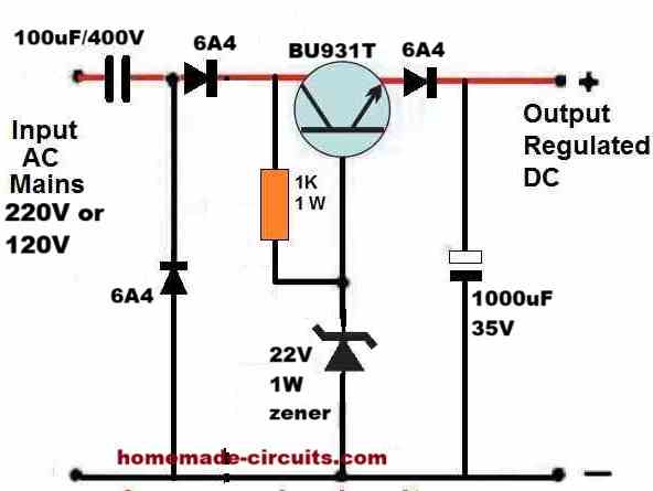
Here’s the circuit you can try for implementing the required design:
Please note that it is extremely dangerous to touch this circuit in an open and switched ON condition, extreme caution is advised…
Let me know how it goes…
Just one small question Sirji! Am I free to use any alternatives if any component is unavailable? And is the capacitor at the input end of Aluminum type because polarities aren’t displayed there? Are the details about this ckt available anywhere on HMC site? That wud make my job more easier to understand and handle.
Thank you again, Sirji !!
Maddy, yes the input capacitor must be a non-polar capacitor, it can be a PPC, or an MKT or an aluminum, all will work as long as it is non-polar type.
The transistor can be any BJT transistor, Darlington type, rated at 400V 10 amp.
Diodes must be rated at minimum 400V 6 amps.
If the 1k resistor heats up, you can replace it with a 10k 1 watt or 2 watt, and check the response.
The output capacitor can be any value above 100uF, 35V.
But please remember that the entire circuit and its output will be floating with mains 220V AC and therefore is extremely dangerous to touch, it must be NEVER be used as an open adapter with an exposed output….
Let me know if you have any further doubts…
Thanks for all the work and support you do, can I use two 1uf 400v capacitors in parallel instead of the 2uf 400v.
Thank you
John
You are most welcome, yes, you can use two 1uF/400V in parallel, in place of a single 2uF/400V
In the circuit diagram for LED series (drawn with actual components), a resistor to block AC in surge current when the capacitor acts as a short is missing.
Also what is the MINIMUM number of LEDs in series you can drive with this circuit?
Please see the message written in blue below the diagram…And also read the warning in RED…
You can use any number of LEDs, from a single LED to 100 LEDs for, a 220V AC supply input.
So the “33 Ohm 2 watt resistor in series” resistor value (as per blue message) needs to be increased as the number of LEDs decrease…right?
No, that resistor is just for controlling the in rush surge current, it is not for controlling the LED current. LED current is controlled by the input PPC capacitor.
Actually it can be just a 10 ohm 1 watt resistor for all circumstances.
A 10 ohm NTC thermistor could be the best choice instead.
Hello again Sir, first of all, I take my hat off to your projects, I wanted you to know that. Your power supply circuit without transporter No. 2 also has a 12 volt zener diode. Zener diodes says parallel permissions to increase the power you were saying, can I connect it, my friends suggested it, but I still want to ask you as an expert
Best Regards
Hi Metin,
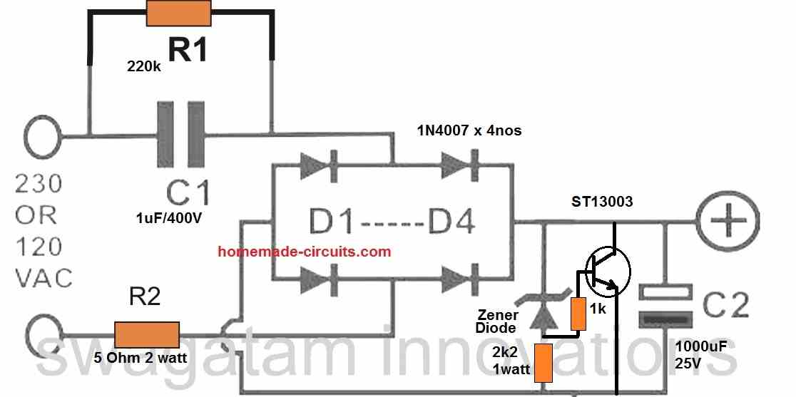
are you referring to the following diagram?
In this design the zener can be a 1 watt zener because the transistor is doing the actual voltage control by shunting the excess voltage.
The output power is decided by the PPC capacitor, zener diode controls the voltage only.
Thank you very much
Best Regards
Metin
Hi Sir,
I made the transistor one of the No. 1 circuit. But I get the output voltage 20 volts instead of 12 volts. Is this normal? I also used its counterpart, the d882, as a transistor. Does this cause problems
Best Regards
Hi Metin, are you referring to the following diagram:

please reduce the zener diode value to 9V at the base of the transistor and check the response, and let me know…
I solved the problem. Thanks a lot
Best Regards
Glad it is solved now!
Dear Sir
May I run 12vDc@ 130 ma Fan with capacitive reactance circuit?
Hi Nitesh,
Yes you can run it with a capacitor value of 2.2uF/400V, but I hope you are aware of the dangers of electric shock with this type of circuits.
Thanks
For the last circuit I will appreciate if you can help with some modifications I can put in place to be suitable for a12v dc output. Is the 1k ohms resistor ok and what should be it wattage?
Hi, there was a mistake in the previous circuit, so I have changed it with a new design.
For 12V output, you can try using a 20V zener diode for the ZX zener diode, and also add a 7812 IC at the output for the load.
Hi,
Referring to the first circuit. I’m curious if it is possible to connect DC-DC buck converter (based on LM2596S IC) directly to rectified 310V, exclude zener diode from the circuit and use regulated low output DC voltage.
I see that buck converter input voltage range is 3-40 VDC, but as long as capacitor at input AC side is limiting the circuit current, will it be safe for buck converter? It would be a cheap small current power supply unit.
Thanks beforehand.
Hi, No, it won’t be safe for the LM2596 because the surge current can destroy the IC, if zener diode is not used. If the zener diode is used then current will be dissipated through the zener and wasted. Moreover the the buck converter i designed for high current operation, which the capacitive power supply cannot supply without wasting power. So overall it cannot be used.
Instead you can design your own efficient 310V SMPS circuit using the following calculator.
https://www.homemade-circuits.com/smps-transformer-calculator-2/
I just have a bunch of 18W LED driver PCBs laying around, based on FM8502C IC. I checked output on load and measured 240mA. What would be the simplest and effective way to turn this device to a stable 5V supply? Or maybe use as a mobile charger?
Do you know the output voltage of the driver? Please measure the output voltage and let me know, I will try figure out.
Two types of PCB, one based on FM8502C, another on BP2867D.
The first has output open voltage of 72 VDC, the second 150 VDC. Both of them are able to provide maximum 300mA.
I measured the load current when connected output to 3.6 V/0.5 A flashlight halogen bulb, it was drawing 300mA continuously with merely glowing. Kept circuit connected for around 5 minutes, neither IC got any hot, not even warm (23 ambient temperature, without heatsinks).
So, it seams those chips have internal protection and keep current limited and constant.
Primarily these boards are designed for driving LED 18W tubes.
With a 72V DC as the source you can probably use the following circuit to get an nice 5VDC output for any relevant applications. However a 300 mA current may not be sufficient enough to charge mobile phones quickly:
https://www.homemade-circuits.com/adjustable-1-2v-to100v-dc-buck-converter-circuit-using-lm5164/
Thanks for your time and attention mate.
I guess these driver boards are really intended for one particular goal – to drive LEDs with appropriate constant and optimum current for their application.
Not worth to further modify or adapt to other needs.
Sure, that makes sense! It is better to use them for driving LEDs only.
I require 220 v ac to 110 v dc (50 ~110v) transformerless power supplu circuit for inductive load.
can you help in this regard.
Sunil
A Transformerless power supply will be low current and non-isolated, what is your output current requirement?