• Skip to main content
  • Skip to primary sidebar

Homemade Circuit Projects

Need circuit help? Post them in the comments! I've answered over 50,000!

Blog | Categories | About | Contact | Calculators-online
You are here: Home / Voltage Control and Protection / High Power Industrial Mains Surge Suppressor Explored

High Power Industrial Mains Surge Suppressor Explored

Last Updated on January 3, 2024 by Swagatam Leave a Comment

In this post I have explained a high energy surge suppressor circuit using high capacity industrial MOVs for suppressing high current mains surges in industrial electrical lines.

The Circuit Problem:

I've been reading a lot of your design ideas and I am extremely impressed with your designs. I don't have anywhere near your level of expertise, but I can follow directions very well.

I read about your household mains surge suppressor and would like to know if it would be possible to build a portable version for my RV.

What we have now, is automatic and will cut the power to the RV, if the input voltage goes too high, or too low. The unit we have was very expensive and would have to be replaced, if we ever experienced a spike in input voltage.

If your mains design could be converted for portable use, I would love to build myself one. Like I said, I am very good at following directions and using a wiring diagram.

I would just need a parts list. Our RV is normally supplied from a double pole 50AMP circuit breaker. Nothing in the RV uses 240V, so they just split the load between the two 120V inputs.

There are other circuits of yours, that I would like to build. I just need the parts lists and direction guidance. I am sorry if I am being a burden, I wish I had the knowledge already.

Thank you,
Gary

Analyzing the Circuit Issue

Hello Gary,

Thanks very much! Can you please elaborate a bit what an RV is? and also please provide the load specs in terms of voltage and current for operating this equipment.

Sorry about that. An RV is a recreational vehicle. When we stay at a campground, we hook into their power pedestal. It supplies either 30AMPS/120V, or 50/100AMPS 120V.

Nothing in the RV uses 240V power, so power is drawn from either hot leg. Our 50AMP service uses a NEMA 14-50R receptacle and the 30AMP uses a TT-30 receptacle.

The 50AMP uses both hots from a double pole 50AMP breaker and the 30AMP uses the hot leg from a single pole 30AMP breaker.

I would like to adapt your house mains surge suppressor, for use with my RV. I would need to make both the 30AMP version and the 50AMP version.

The power I have access to, depends on what is available.

The 30AMP, would be single pole and 3,600watts and the 50AMP would be double pole, with 6,000watts on each pole.

Please let me know if this is enough information for you.

Thank you,
Gary

industrial high current MOV varistor device

Solving the Circuit Query 

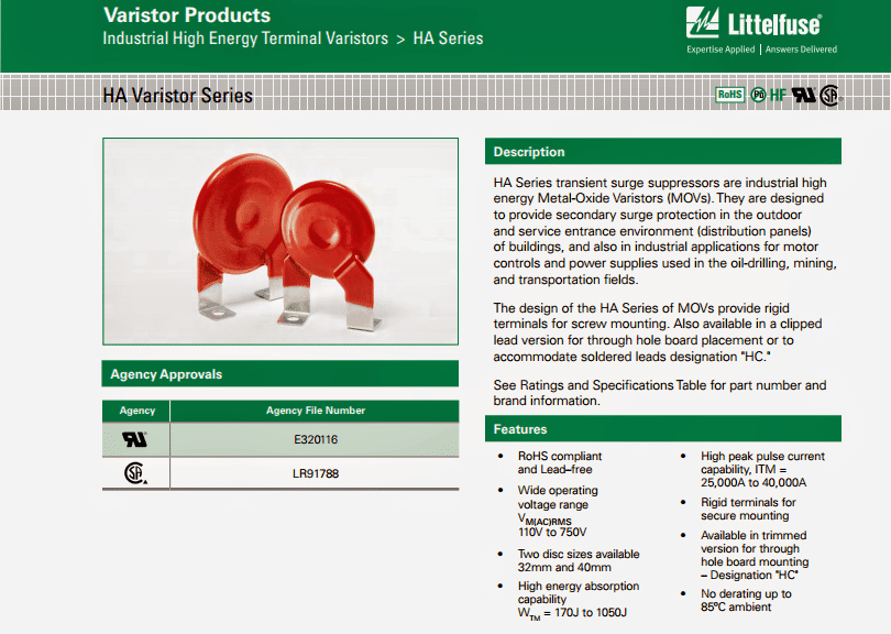
The input high current surge seems to be the main issue in the above discussion, which could be effectively tackled using a High Energy Industrial Metal Oxide Varistor (MOV), the details may be studied in the following image:

industrial high energy terminal varistors

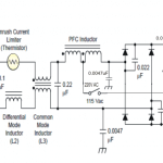
The high energy varistor as discussed above should be installed into the power lines as shown in the following diagram:

Circuit Diagram

how to connect a high energy varistor on mains AC input

You'll also like:

  • 1.  How RCCB Works [with Circuit Diagram]
  • 2.  Mains AC Home Protector Circuit
  • 3.  Do We Need a Freewheeling Diode Across the Inductor in Boost Converter?
  • 4.  SG 3525 Automatic PWM Voltage Regulation Circuit
  • 5.  Mains AC Short Circuit Breaker/Protector – Electronic MCB
  • 6.  Triac Phase Control using PWM Time Proportional

About Swagatam

I am an electronics engineer with over 15 years of hands-on experience. I am passionate about inventing, designing electronic circuits and PCBs, and helping hobbyists bring their projects to life. That is why I founded homemade-circuits.com, a website where I share innovative circuit ideas and tutorials. Have a circuit related question? Leave a comment.... I guarantee a reply!

Previous Post: « Incubator Reverse Forward Motor Controller Circuit
Next Post: Simple RGB LED Controller Circuit »

Reader Interactions

Need Help? Please Leave a Comment! We value your input—Kindly keep it relevant to the above topic! Cancel reply

Your email address will not be published. Required fields are marked *

Primary Sidebar

Subscribe to New Circuit Ideas

Categories

  • Arduino Projects (87)
  • Audio and Amplifier Projects (132)
  • Automation Projects (17)
  • Automobile Electronics (101)
  • Battery Charger Circuits (82)
  • Datasheets and Components (102)
  • Electronics Theory (143)
  • Free Energy (37)
  • Games and Sports Projects (11)
  • Grid and 3-Phase (19)
  • Health related Projects (25)
  • Home Electrical Circuits (12)
  • Indicator Circuits (14)
  • Inverter Circuits (87)
  • Lamps and Lights (142)
  • Meters and Testers (69)
  • Mini Projects (46)
  • Motor Controller (64)
  • Oscillator Circuits (27)
  • Pets and Pests (15)
  • Power Supply Circuits (108)
  • Remote Control Circuits (50)
  • Security and Alarm (64)
  • Sensors and Detectors (100)
  • Solar Controller Circuits (59)
  • Temperature Controllers (42)
  • Timer and Delay Relay (49)
  • Transmitter Circuits (29)
  • Voltage Control and Protection (37)
  • Water Controller (36)

Calculators

  • Battery Back up Time Calculator
  • Capacitance Reactance Calculator
  • IC 555 Astable Calculator
  • IC 555 Monostable Calculator
  • Inductance Calculator
  • LC Resonance Calculator
  • LM317, LM338, LM396 Calculator
  • Ohm’s Law Calculator
  • Phase Angle Phase Shift Calculator
  • Power Factor (PF) Calculator
  • Reactance Calculator
  • Transistor Astable Calculator
  • Transistor base Resistor Calculator
  • Voltage Divider Calculator
  • Wire Current Calculator
  • Zener Diode Calculator
  • Filter Capacitor Calculator
  • Buck Converter Calculator
  • Boost Converter Calculator
  • Solar Panel, Inverter, Battery Calculator
  • Wire Current Calculator
  • SMPS Transformer Calculator
  • IC SG3525, SG3524 Calculator
  • Inverter LC Filter Calculator

People Also Search

555 Circuits | 741 Circuits | LM324 Circuits | LM338 Circuits | 4017 Circuits | Ultrasonic Projects | SMPS Projects | Christmas Projects | MOSFETs | Radio Circuits | Laser Circuits | PIR Projects |

Recent Comments

  • Swagatam on Simple Delay Timer Circuits Explained
  • Swagatam on Timer Based Cell Phone Charger Circuit
  • Swagatam on 10 LED Tachometer Circuit Diagram
  • Göran on 10 LED Tachometer Circuit Diagram
  • Nitesh Agrawal on Timer Based Cell Phone Charger Circuit

Company

  • Privacy Policy
  • Cookie Policy
  • About Me
  • Contact
  • Disclaimer
  • Copyright
  • Videos
  • Sitemap

Social Profiles

  • Twitter
  • YouTube
  • Instagram
  • Pinterest
  • My Facebook-Page
  • Quora
  • Stack Exchange
  • Linkedin
  • © 2025 · Swagatam Innovations