In this post I have explained the making of a parallel path overunity device through a few magnets and coils.
What is Parallel Path Technology
Parallel path technology was first introduced by Mr. Joe Flynn and it's also called the Flynn's concept. In this concept or theory, a relatively weaker electromagnetic influence is used for aligning the magnetic fields of a few permanent magnets over a particular point enabling a massive force to generate over that particular side of the unit.
We know a lot about permanent magnets, and have seen how these natural power devices are able to stick or cling over ferromagnetic surfaces due to their inherent force of magnetic attraction.
However this property of magnets no matter how strong it may be have proved useless as far as the creation of perpetual energy is concerned or for devising overunity machines.
Very interestingly, Mr. Joe Flynn could devise a method through which it became possible to channelize the magnetic force of permanent magnets on particular directions with the help of a relatively smaller calculated electricity input.
Building the Parallel Path Device
The following paragraph explains the making of a parallel path over-unity device using ordinary electrical elements and a circuit:
Parallel path as the name suggests makes use of two parallel ferromagnetic plates arranged as shown in the following figure:
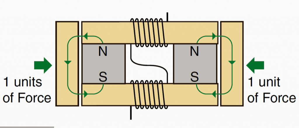
We can see a couple of horizontal plates sandwiching two permanent magnets between them at the ends.
Two vertical plates can also be seen positioned across the ends of the horizontal plates.
And the central vacant section of the horizontal plates possess coils of wire around them which are interconnected with each other and terminated for accepting an electrical potential or voltage.
Without any electricity applied to the coils, the vertical plates are subjected with a magnetic force of attraction that may be equal to the strength of the fields of the enclosed permanent magnets.
We can assume it to be unit 1 since the force is the fundamental force of attraction from the magnets and are equal on both the sides of the system.
Applying Electricity to the Assembly
Now, if a calculated magnitude of electricity is applied to the central coils, an amazing phenomenon could be seen happening, which is of course not so amazing rather more scientific and seems to be obeying the standard laws of magnetism........ yet you would find it very impressive.
Depending on the polarity of the applied electricity, the magnetic lines of fluxes get aligned and neutralized on the particular sides of the plates respectively, generating a massive accumulation of magnetic force on one particular side, and zero force on the opposite side.
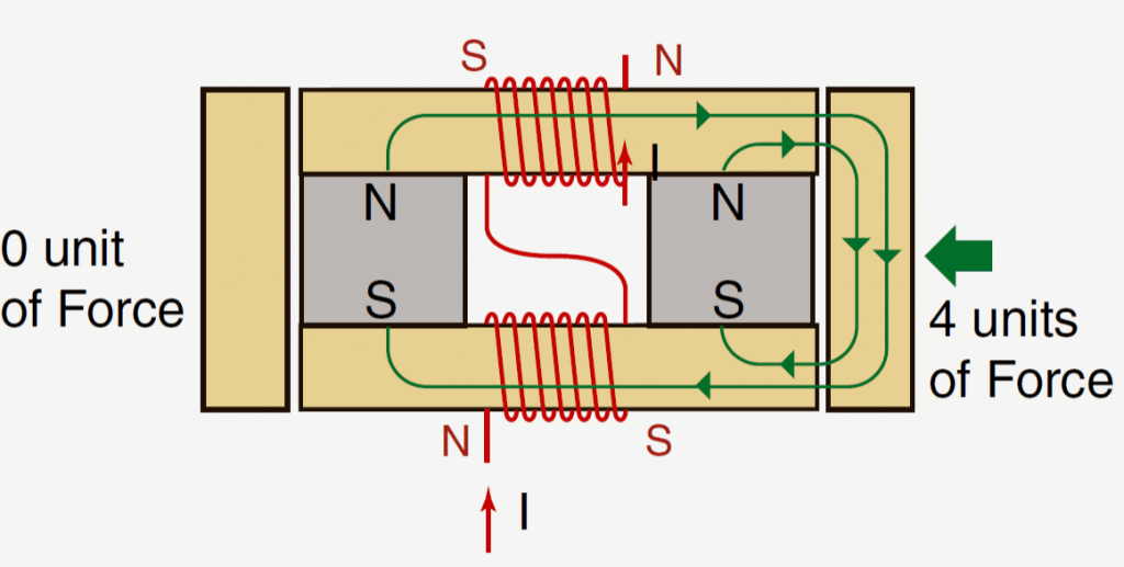
The above situation gets reversed as soon as the polarity of the electricity is reversed, as shown in the following figures.
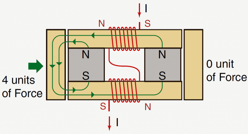
Attaining the 4X Overunity
The most impressive and intriguing fact regarding the above implementation is the magnitude of force that is being achieved on the opposite sides, as shown in the above diagram it's 4 units on one side and zero on the other side.
It's proved that it takes the electric power of just 1 unit, that refers to the magnetic power of one enclosed magnet, to create the indicated 4 units of force.
Since the above actions can be flipped across the sides simply by flipping the polarity of the input electricity, we could be able to enforce the actions into a practical motion or a linear motion through some suitable mechanism, which would respond with 4 times more force than the conventional electromagnet operated devices.
The above theory looks absolutely feasible and have been tried out successfully by many enthusiasts.
Applying in Airplane Motors
Presently it's being tried for creating super efficient airplane motors.
Actually the applications could be diverse, it just needs an innovative smart approach for converting this concept into something which normally nobody would want to discuss openly...yes it's the overunity results which can be implemented using this theory, which looks quite obvious from the above theory.
If you have already made a parallel path device in your home, do let us know about its overunity results and additional benefits achieved through its specific applications


Questions & Answers
Please, if you have the construction plans for the Parallel Path Overunity device and if you agree, send them to me by mail. Thank you in advance!
I had tested it some 5 years ago and I was amazed to see the immense increase in the magnetic force in response to a small input supply.
However, even though the magnetic force increased maybe 10 folds, its attraction distance did not go beyond 3 or 5 mm, so practically it seemed useless.
However, once it attached itself to an iron, pulling them apart took a lot of effort, so strong it was.
swagatam have you built one or is this a thought experiment.
Hello James, I have built and tested this project thoroughly and it worked excellently for me.
has anyone made one yet ? I’ve seen several on the net but no real depth of explanation.the question of the windings and polarity needs to be resolved . if the diagrams are wrong everybody is screwed. why do they do that ? I’ve seen it over and over again. I’m in the middle of replication and having no luck yet .
I have an idea of using this concept to achieve an overunity output without the need of permanent magnets but by using only electromagnets and applying lenz law.the magnetic field generated due to load can be used instead of permanent magnets to achieve the same results and with an advanced innovative approach a feedback loop can be achieved to boost the energy of the system
Dear, this remembers me a “hybrid actuator”
I’m working on an instrument that can generate high vibration force ( like hammering)combined with small displacements and frequency about 10-20 Hz.
Suppose your two vertical members are mechanically interconnected and represent the “hammer”. I want a vibration that is more effective in one of the two directions. (Compare it with an old door bell, containing two ringing shells with different tones and a vibrating hammer between them. My intension is, by changing the coil current direction to hear only one of the two bells.)
In your fig.1 (= rest position) you have 2 air gaps and consequently a small unbalance will result in a steady but bistable situation where one of the vertical ferric elements will be attracted. Breaking this stable position need the two coils to generate (together) an inverse magnetic field higher than that of the permanent magnet. Taking in account that the attraction forces in an air gap are very dependent of the gap width, I’ not sure that a hybrid concept is more effective than a simple variable reluctance system whereby the central vibrating”hammer” is suspended by a band spring.
Hi, your coil diagram is incorrect. The magnetic polarity of the upper coil is marked as being opposite to the bottom coil. However the winding is identical. To achieve the marked result either the winding rotation, from clockwise to counterclockwise, or the direction, left to right instead of right to left, must be changed, but not both!
By the way, an inventor in the mid 19th century searched for a magnetic null region in the horseshoe, I believe, and found one. He then developed a mechanical motion generator strong enough to run a sewing machine. His invention was not widely know and when so, was considered a toy due to the low power output, less than 500 watts eq. A mechanical shove would get it going and it would continue until overloaded inadvertently or intentionally. (Or if the fixed magnet depletes.)
Also, fixed magnetic fields used for energy production tend to demagnetize when using opposing force but not so when utilizing attaction forces. Makes sense if one gives it a little thought.
Thank you for your valuable information! Appreciate it!
ola´boa noite
sou valdemiro moro no rn brasil , olha sobre meu conceito acho pode funcionar , mais um interruptor abrindo e o outro fechando . mais os dois fechando ao mesmo tempo . acho que funcione amigo
Thanks a lot for the reply, it does helped.
if I apply this design for dc bulk converter, am I on the right track?
can I use this design for a single 100ah 12v car battery to be charging two 12v (120ah each) battery? kindly put me through.
this device is for mechanical application, for getting 4X more magnetic force from a 1X input….it cannot be used for charging a battery?
Interesting device. It could be more interesting with data (Amps, Teslas,Volts, etc)
thanks, I'll investigate and try to update the same…
Please sir, i want to remove the screen of a cellphone and replace it with two wire output that i can connect to the video input port of a TV set so that the phone's data can be display on the TV screen. And i want to do this with phones that have T-Flash(memory card) especially any China phone with T-Flash. Please is it possible? If yes how do i go about it? Thanks
jideofor, sorry, that's not possible…