In this article I will try to explain the construction of a 1.23 V to 50 V adjustable switching power supply circuit using the IC LM2576.
The LM2576 family of regulators is a monolithic integrated circuit that performs all of the active operations of a step-down (buck) switching regulator. It offers exceptional line and load stabilization and can handle loads upto 3 amps.
These ICs can be configured to generate 3.3 V, 5 V, 12 V, 15 V fixed output voltages. Additionally this chip can be also wired like a variable voltage power supply, with a maximum output range of 1.25 V to 50 V.
Remember, there are different versions of the LM2576 IC for generating the above mentioned specific fixed output voltages, and the adjustable output voltage.
Meaning, a 5 V version can be used for generating only a 5 V fixed voltage output, a 12 V version for generating a fixed 12 V output, and so on.
Likewise, for getting an adjustable output voltage, you will have to specifically select the adjustable (ADJ) version of the LM2576 regulator IC, and configure it according to the given circuit diagram.
Why the Adjustable Version of LM2576 is more Efficient
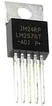
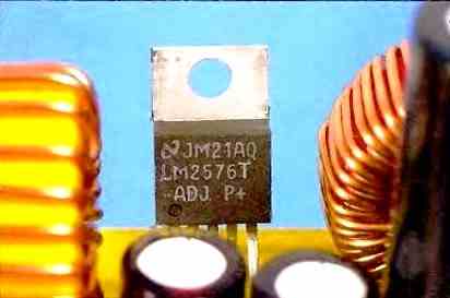
The adjustable version of the LM2576 is indicated by the letters ADJ on the device, as shown in the above figure.
The adjustable version of the LM2576 appears to be more efficient because of the following reasons:
This chip can be configured as an adjustable switching regulator, simply by configuring a potentiometer across its feedback pin.
Additionally, the adjustable version can be also used as fixed output voltage regulator by replacing the potentiometer with a resistive divider across its feedback pin.
Switching Regulator Vs Linear Regulator (What's the Difference?)
So, what's so special about using a LM2576 based switching regulator, instead of a linear regulator such as an LM338 based regulator?
The main advantage of using an LM2576 regulator is that, it uses a switching PWM across an inductive buck converter stage. The switching PWM across an inductor causes the output voltage regulation by controlling the back EMF from the inductor. This causes the output regulation to be very efficient, with minimum heat dissipation.
Since the heat dissipation is minimum, the power loss is minimum at the output. Meaning, in a switching regulator the output V x I is very near to the input V x I.
On the contrary, linear regulator ICs like LM338 or LM317 or L200 regulate their output voltage by dissipating a lot of heat through their body. The temperature dissipated by these ICs is dependent on the load current and the difference between the input voltage and the output voltage. As this difference increases the heat dissipation also increases. This makes linear regulators extremely inefficient, unless the output regulated voltage is nearly equal to the input voltage.
Functional Block Diagram
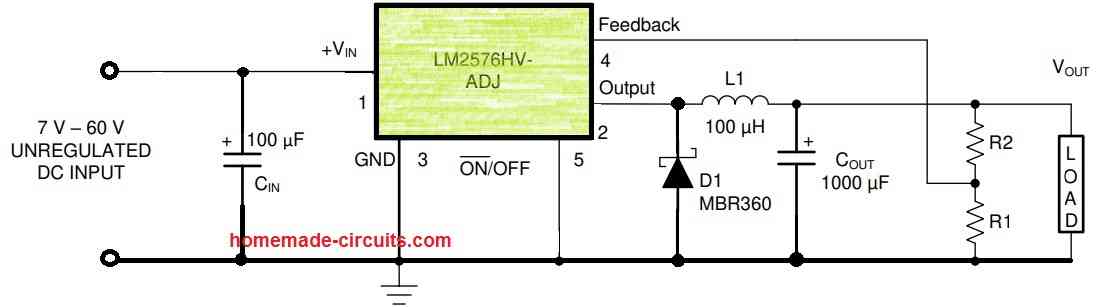
The following diagram shows the functional block diagram and the internal configuration of the IC LM2576. The diagram also indicates how the various pinouts of the IC needs to be configured with the external components to produce the intended regulated output voltages.
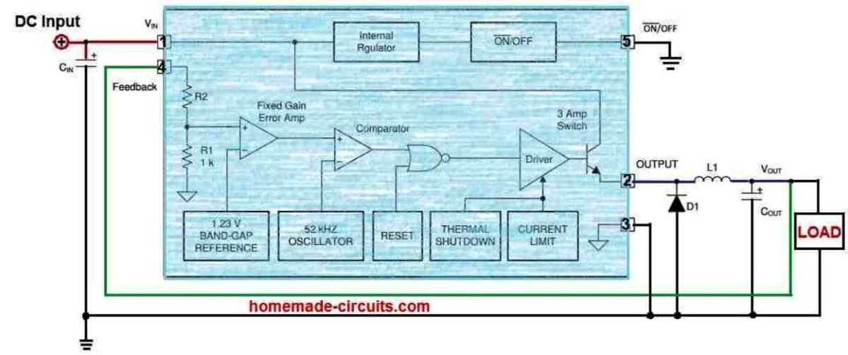
The above block diagram shows the basic set up configuration which can be used for all the fixed voltage version of the LM2576 IC.
Pin Functions
The functions and designations of the IC LM2576 pinouts is explained in the following points.
Pin#1 (VIN): This is the supply input pin which is connected to the collector pin of the internal high-side transistor. This pin should be connected to the power supply and the CIN input bypass capacitors. Make sure to use the shortest possible link between the VIN pin, the high frequency bypass CIN and GND.
Pin#2 (Output): This is the internal power transistor's emitter pin, which is a switching node. We connect the cathode of the external diode and an inductor to this pin.
Pin#3 (Ground): This functions as the Ground pin. The connection reaching CIN should be kept as short as possible.
Pin#4 (Feedback): This pin performs as the Feedback sense input pin. It is to be linked to the junction of feedback divider resistors, to fix VOUT for the ADJ (adjustable) version. Alternatively, this pin could be also hooked up straight with the output capacitor for the fixed output voltage version IC.
Pin#5 (ON/OFF): This pinout works as the Enable input to the voltage regulator. A High on this pin causes the IC to switch OFF and a low on this pin allows the IC to remain switched ON. This pinout can be simply connected with the ground line to keep the regulator in the enabled mode. Never keep this pinout open or unconnected.
IC Tab: This terminal is supposed to be connected with the GND. Being the tab of the IC this must be screwed to a suitable heatsink for thermal dissipation.
How to Build an Adjustable LM2576 Switching Power Supply Circuit
Parts List
- R1 = any resistor between 1 K an 4.7 K (1/4 watt 5%)
- R2 = 47 K Potentiometer
- Cin, C1= 100 uF/63 V Electrolytic
- Cout = 2200 uF/63 V Electrolytic
- D1 = 1N5822 Schottky Diode
- IC = LM2576HV-ADJ
- L1 = 150 uH Inductor 5 amp
- L2 = 20 uH 5 Amp
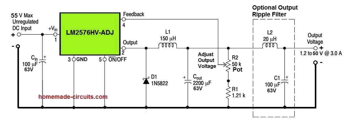
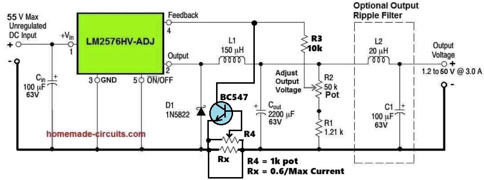
The above diagram shows a simple 1.2 V to 50 V switching power supply circuit using the LM2576HV-ADJ IC, which can produce a maximum output current of 3 amps.
The various switching parameters involved with the above circuit can be learned from the following points:
An unregulated 55 V DC input is applied across pin#1 which is the VIN pin of the IC and pin#3 which is the ground pin of the IC.
The capacitor Cin is installed close to the above pinouts to ensure effective ripple rejection across the input DC pins of the IC.
As soon the IC LM2576HV-ADJ is powered as explained above, its internal PWM oscillator becomes active.
The PWM oscillator internally starts generating a calculated amount of PWM. The duty cycle of the PWM depends on the feedback voltage applied to pin#4, via the resistive divider pot R2 and R1.
This calculated PWM is supplied to the external buck converter stage comprising of L1, D1 and Cout via the output pin#2 of the IC.
The L1, D1 and Cout appropriately respond to the PWM to produce an optimized DC output voltage, reduced to the desired level (between 1.2 V and 50 V).
It is important to know that the current will be 3 amps at the maximum 35 V or 50 V outputs. This means, for lower output voltages the current will be proportionately higher.
Pin#5 is the ON/OFF or the shutdown pinout of the IC LM2576HV-ADJ.
As long as this pinout has a potential of less than 1.2 V DC, the IC remains functional and active.
However, if the potential on pin#5 exceeds 1.4 V, the IC LM2576 goes into a shutdown mode. This causes the output voltage to instantly shut off.
Despite of superb output voltage and current regulation, there might be some ripple DC content at the output.
To counter or eliminate this ripple content, you can add the "optional output ripple filter" stage at the output of the circuit, as indicated in the circuit diagram.
Using the Adjustable Version to get Fixed Output Voltages
As discussed earlier, the adjustable version of LM2576 IC can be also configured to get fixed voltage outputs, simply by replacing the R2 pot with a fixed calculated resistor.
An example of this design can be witnessed in the following diagram:
R2 can be calculated using the following formula:
R2 = R1 ( VOUT / VREF - 1 )
where VREF = 1.23 V, R1 can be any value between 1 k and 5 k
Reference: ti.com

Questions & Answers
Hi, I’ve seen your article with the LM2576 based power supply and I would like to make an lab power supply with it. my question is if you can add a variable current limiter circuit on it so that not only the voltage will be adjustable, but the current as well. Thanks.
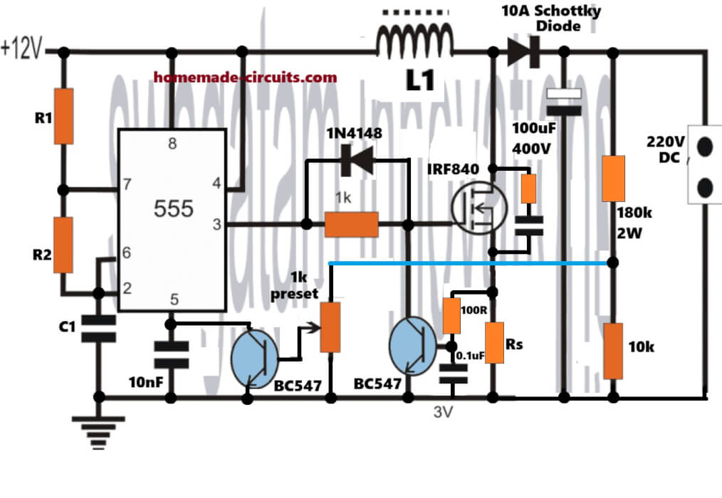
Hi, a current control in a LM2576 power supply circuit can be perhaps added in the following manner, please check it and let me know:
can i use a lm2596t adj ic instead of the lm2576 ic in the adjustable switchmode power supply.would diferent sized inductors cause problems?
You can use it but you will need to modify the circuit according to he Adjustable design…the inductor must be exactly as suggested in the original diagram…
So I just have to use this IC at the input and connect the output of this IC to the 5v motor.?
Yes, You can build the following circuit and use it to convert 48V to 5V DC:
Hey there how are you? So I was working on this circuitry which you have suggested me before and now I am facing some issues can you help me to solve it ?
1. The output is increasing slowly and it’s going upto 9volts and if I connect 5v Motor at the output the voltage will fall down at the 1.2v why ? I have cross checked everything connections !
Hey, please provide the input voltage and current specifications, and also the motor voltage and current specifications?
The input voltage is 12v and the motor voltage is 5v
Please provide max current also…
A 5v dc motor won’t taken more then 2amps !
The output voltage will drop if the input source current is not sufficiently rated for the load, or the inductor wire is not sufficiently thick to handle the load current, or the IC is heating up.
Sir I got the issue I was using lm2576 ADJ and not the fixed voltage ic and i was using circuit for fixed voltage so now I have it replace the ic to the fixed voltage version!
Thanks Alfa, for updating the results.
I hope the issue is solved now for you.
Not now but I will solve it after purchasing lm2576hv – 5v !
Ok, got it! thanks for the feedback!
So with this I can easily regulate 48v 400w to 5v ?
Yes, you can.
But it’s a bit difficult to make I think what’s the voltage of the capacitors used in this circuit!
Input capacitor must be 100V, output capacitor can be 25V
What about the inductor?
?? What’s the spacifications of the inductor?
It’s given in the image, 100uH, any ferrite type coil with 100uH will do. The wire can be 0.5mm thick.
And what about the amps ? 100uh inductor with 2 amps ?
For 2 amps you can use a 1 mm thick wire.
What would happen if you tweak the up or down? feedback voltage to alter the output voltage
The output voltage will vary accordingly..
Ok, where can I upload the scheme
you can send to
contact
@
homemade-circuits.com
Hi thanks for your quick response, the source is a variable power supply from 0 to 30v x 5A with Lm358 op amp,
Hi, without seeing the schematic it may not be possible for me to suggest where the protection circuit can be added.
Your circuit will need a current controller stage added somewhere in the circuit.
Hello good afternoon my name is Carlos, can you tell me how I can protect my power supply? Since I have connected a winding and when I have disconnected it… The source is damaged, the power transistors were shorted and the display is damaged… Now I have bought another Display and the transistors…. How can I protect the power supply so that it does not happen again?… Thank you very much in advance.
I will have to see the schematic of the power supply, without seeing the schematic it is difficult to suggest a protection circuit.
Thank you very much, one more question… what is the value of Rs
## Comment by Carlos is not Related to the above article.. ##
Rs can be = 0.2 / Current
So your current should be able to generate 0.2V across the Rs resistor
Could you design please? Thank you very much.
You can try the following circuit:
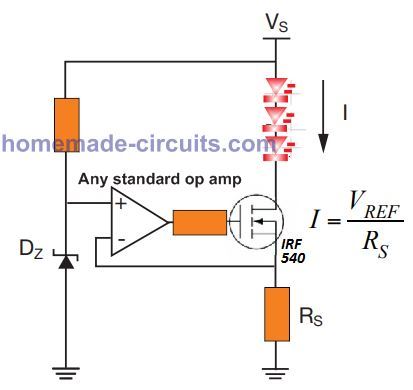
To ensure the transistor activates even 0.2V, remove the zener diode and connect the (+) input of the op amp to ground.
The mosfet can be replaced with any standard BJT.
The resistor connected with the (+) input of the op amp can be removed, and the transistor base resistor can be a 1K or depending on the LED load.
Thanks for your quick response, I can’t change the resistor because that resistor is part of the power supply itself, and if I change it, the supply doesn’t work well
Yes, in that case you will need an op amp based circuit.
I tried the circuit with transistor, but doesn’t work because the shunt resistor is 0.1 + 0.22 + 0.22 in parallel so the voltage on 56 ma is too lower And the transistor doesn’t turn on… By the way Perhaps I need a circuit with opamp… I don’t know.
The formula is
R = 0.6 / current
R = 0.6 / 0.056
= 10 ohms.
So the resistor should be 10 ohms.
Then the LED will light up.
Hello, good afternoon, Mr. Swagatam, my name is Carlos and I am a faithful follower of the website… This time I want to ask you for a circuit… I have a variable power supply in voltage and current. I need a circuit that can detect when 50 to 60 milliamps pass through the shunt resistor… in order to turn on a led (optocoupler) or a relay… Thank you very much in advance.
Thank you so much Carlos,
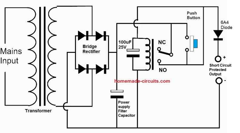
You can try implementing the following configuration:
RX = 0.6 / 0.06(60mA)
please can I get the list of components with their popular names.
I have updated it under the first circuit diagram, you can check it.
Is there a way to get higher amps (3amp max) from the first circuit diagram?
You can add the following transistor stage at the output of the circuit
Beautifully explained functions of this IC – LM2576 with diagrams shall try to get this IC & try it out, keep up the good work Swagatham
God bless you
Thank you so much Val! Glad you liked the article and hope you will try this project someday and give your precious feedback to all the keen visitors here!