A metal detector is useful electronic device which can detect the presence of metal object nearby. We can find these device in security systems, airports, shopping malls and many other places.
In this article we will learn how to make two simple metal detector circuits using popular 555 timer IC.
Both circuit are designed to produce an audible sound and the sound change when a metal object is brought close to the sensing coil then.
First circuit uses a ready made 10 mH inductor, while the second circuit uses a homemade air core search coil.
So now these are simple experimental circuits and can be useful for beginner who want to understand how an inductor can be used for metal detection.
1. Metal Detector Circuit Using a 10 mH Inductor
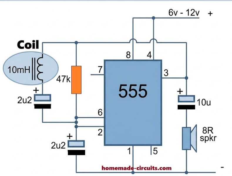
This is simple metal detector design in which a small 10 mH inductor works as sensing element.
The circuit uses 555 timer IC to create an audio frequency signal.
When metal object is brought near inductor, then its inductance and electrical characteristics change. This affect the signal produced by the circuit and causes change in the sound.
Components Required
| Component | Value | Quantity |
|---|---|---|
| IC | NE555 | 1 |
| Inductor | 10 mH | 1 |
| Resistor | 47 kΩ | 1 |
| Capacitor | 2.2 µF | 2 |
| Capacitor | 10 µF | 1 |
| Speaker | 8 Ω | 1 |
| DC supply | 9 V | 1 |
Circuit Working
555 IC works as an oscillator and produces a continuous square wave output. 47 kΩ resistor and the associated 2, 2 µF capacitor help determine timing of oscillator, the 10 mH inductor forms sensing element.
When a metal object comes near the inductor, then magnetic field around the coil interacts with the metal.
This can change the effective inductance and impedance of sensing network. As a result, the electrical signal changes and the speaker produce a different sound.
Now the 10 µF capacitor is used in the speaker output section to reduce the DC component reaching the speaker.
Construction Notes
Use a good-quality 10 mH inductor and keep it away from other large magnetic components.
The circuit can be assembled on a small general-purpose PCB. Keep the connections short, especially around the inductor and timing components.
A 9 V supply can be used for initial testing, but the supply should be capable of providing the required current.
2. Search Coil Metal Detector Using 555 IC
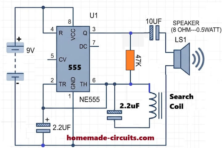
This version uses an air-core coil instead of a ready-made 10 mH inductor.
The coil can be made by winding enamelled copper wire around a circular former. This makes the project more interesting because we can experiment with the coil dimensions and observe how the sensing response changes.
Components Required
| Component | Value | Quantity |
|---|---|---|
| IC | NE555 | 1 |
| Resistor | 47 kΩ | 1 |
| Capacitor | 2.2 µF | 2 |
| Speaker | 8 Ω | 1 |
| DC supply | 9 V | 1 |
| Enamelled copper wire | Suitable gauge | As required |
Making the Search Coil
Take a circular plastic former having approximately 10 cm diameter.
Wind around 170 turns of enamelled copper wire over the former. Keep the turns close together and make sure that the winding is reasonably uniform.
After completing the winding, remove the enamel insulation from both wire ends using a suitable method. These two ends will be used for connecting the coil to the circuit.
Do not use a metal former because it can affect the coil's operation.
Circuit Working
The 555 IC generates a continuous square-wave signal. The homemade coil forms part of the metal-sensitive network.
When no metal object is near the coil, the circuit produces its normal audio tone.
When a metal object is brought near the coil, the electromagnetic interaction changes the coil's electrical characteristics. This changes the oscillator response and the sound produced by the speaker.
The sound may become higher or lower depending on the actual circuit arrangement and the type of metal being tested.
Construction Notes
The coil should be mounted on a plastic or wooden support.
Keep the coil away from the speaker magnet and other magnetic objects because they may affect the sensing response.
Also, do not assume that every wire thickness will produce the same result. The wire diameter, number of turns and coil dimensions all affect the inductance.
Understanding the Metal Detection Principle
Main component responsible for metal detection in both designs is the inductor.
An inductor produces a magnetic field when an electric current passes through it then.
When a metal object is brought near the coil, then magnetic field interacts with the metal. Depending on the metal type and it electrical and magnetic property, the effective inductance and losses of coil can change.
So now these changes affect the electrical network connected to 555 IC, resulting change in the signal can be heard through speaker, this is the basic principle behind these simple metal detector experiments.
Testing the Metal Detector
After assembling the circuit, first switch on the 9 V supply and check whether the speaker produces a continuous sound.
Now bring a small metal object slowly near the sensing coil.
Try testing with different objects such as:
- An iron nail
- A steel screw
- A copper coin
- An aluminium piece
- A small metal key
Observe whether the sound changes when each object is brought near the coil.
Keep the distance between the object and the coil small during the initial testing. These simple circuits have limited sensitivity and should not be expected to detect objects from a large distance.
Conclusion
Both circuits demonstrate how a 555 timer IC and an inductor can be used to make a simple metal detector.
The first version uses a ready-made 10 mH inductor, while the second version allows us to make our own search coil using enamelled copper wire.
These projects are useful for understanding the basic relationship between inductance, magnetic fields and oscillator frequency.

Questions & Answers
I have enjoyed reading your articles for many years. Thank you for taking time to publish them!
I know this is intended as a demonstration, but I am interested in building a simple metal detector to I can save my woodworking blades from hitting nails (and other metal) hiding below the surface in recovered lumber. Instead of listening for a change in tone, would it be possible to have a second 555, not attached to the coil, and out of phase with the main signal, so the two signals cancel each other until metal is detected? When metal is detected by the coil, the frequency of that 555 would presumably change, and you would hear a tone instead of silence. Or would the difference in frequency between the two out of phase signals not be within normal hearing range? Is the 555 stable enough to keep the two signals the same frequency with temperature and other variables? I have a degree in electronics technology, and understand and can build circuits. But I am not an engineer and don’t have design experience. I can experiment myself, but would like to know if what I am thinking is reasonable. Thanks!
Thanks so much for your kind words.
I am glad you have enjoyed my articles over years. Your idea is quite interesting.
In fact, it is similar to a beat frequency oscillator (BFO) metal detector. However two independent 555 oscillators cannot remain perfectly synchronized or 180° out of phase.
Their phase will gradually drift due to small frequency differences caused by component tolerances and temperature change.
Better approach would be to mix the two oscillator signals and listen to the difference frequency which changes when metal approaches search coil. I also have another circuit that might interest you:
https://www.homemade-circuits.com/stud-finder-circuit-find-hidden-metals-inside-walls/
It uses an LC oscillator and 455 kHz ceramic filter to detect nearby metal objects, with a meter indication.
I think it could be worth experimenting with for finding hidden nails and screw inside recovered lumber.
I have not tested its detection depth specifically inside wood, though so some practical testing would be necessary.