In this post I have explained a simple way to enhance the the XL4015 DC to DC buck converter with an adjustable current limiter, which seems to be missing in the original module.
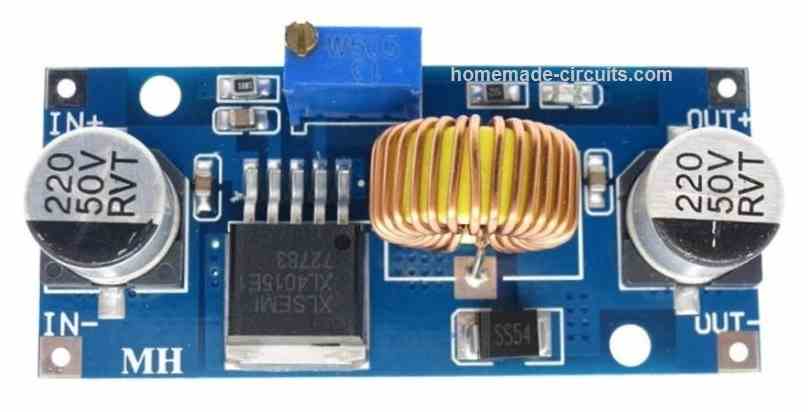
About XL4015
The XL4015 is a 180 KHz fixed frequency PWM buck (step-down) DC/DC converter, specially designed for operating a 5 V, 5 Amp load with good efficiency, minimal ripple and exceptional line and load regulation.
Built using very few number of additional parts, the regulator module is easy to work with and consist of built-in frequency compensation along with a fixed-frequency oscillator.
The PWM control circuit features adjustable duty ratio at a constant rate from 0 to 100%. The IC XL4015 also features an in-built over-current protection functionality.
When a short circuit is detected at the output, the operating frequency is instantly lowered from 180 KHz to 48 KHz, causing an immediate drop in the output voltage and current.
The chip has a fully integrated compensation block, without depending on any external components.
XL4015 IC Main Features
- Broad 8V to 36V Input Voltage Range
- Output voltage is Adjustable from 1.25V to 32V
- Maximum Duty Cycle can be as high as 100%
- Output Drop-Out is merely 0.3V
- Switching Frequency is fixed at 180 kHz
- Output current is constant at 5A.
- In-built Power MOSFETs ensure high voltage/current optimization
- Operating efficiency is very impressive at 96%
- Line and load regulation are extremely good
- IC features an internally controlled thermal shutdown function
- Likewise it also features an in-built current limit function
- Needless to say, the chip also includes an output short protection feature.
Major Disadvantage
Although the XL4015 module is loaded with many excellent features a buck converter needs to have, it lacks one major facility.
The module has no arrangement for adjusting the output current to preferred levels, as per the load specifications.
So if you want to charge a Li-Ion battery with a XL4015 module, say at 2 amp rate, you won't be able to do that, due to the above mentioned drawback.
Similarly, if you wanted to drive a 3.3 V LED at 3 amp maximum current rate, you'd be disappointed likewise, since the module is rated at a fixed 5 amp current.
How XL4015 Works
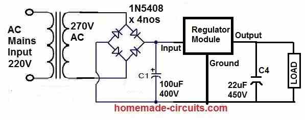
The basic working schmetaic of the XL4015 buck converter is shown below:
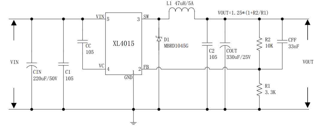
The circuit is configured to produce a fixed 5 V at a constant 5 amp current output in response to a supply input of 8 V to 36 V. The input power specifications has to be higher than the output power, meaning the input supply wattage capacity must be higher than 5 V x 5 A = 25 W.
Therefore, if an input supply of 36 V is used, then the input current should be higher than 25 / 36 = 0.7 Amps. If 8 V is used then the input current may be higher than 25 / 8 = 3 Amps, and so forth.
The internal circuitry of the IC XL4015 consists of the basic elements such as an oscillator and an error amp. The well calculated and controlled 180 kHz oscillator frequency is generated at pin3 (SW) for feeding the external buck converter configuration consisting of the diode, inductor, and the capacitor. This enables the buck stage to process the input supply to a precise 5 V, 5 A output.
The pin2 (FB) functions as the input for the error amp feedback. A minimum of 1.25 V input at this pinout is enough to begin the shut down process for the IC.
This pinout can be seen configured with a potential divider R1, R2, which ensures that the output voltage can never go beyond the 5 V range, which then causes a voltage higher than 1.25 V to develop at the FB pin initiating the shut down process for the IC, thereby preventing the output from crossing the 5 V level.
This also implies that the output voltage could be adjusted to other voltage levels, such as 12 V or 15 V, by suitably varying the R1/R2 feedback divider values.
The R1/R2 can be also fixed using the following formula, for getting the desired output voltage:
Vout=1.25 x (1+R2/R1)
Current Limit Adjust
As we can see from the schematic the XL4015 module does not include a current limiting feature which apparently is a major limitation of the module.
However, the module does include a shut down pinout FB that could be configured with an external current limiter circuit, for accomplishing the feature. This could be implemented as indicated in the following diagram:
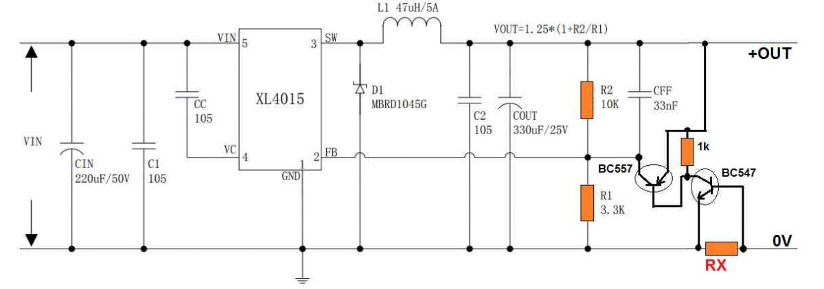
The RX may be calculated using Ohm's law:
RX = 0.2 / Current Limit
Since the two transistors are wired with a very high gain output, a potential difference of just 0.2 V across RX should be enough to trigger the FB pin of the IC and initiate the current limiting action.
As soon the current tends to exceed the desired limit, causes the required minimum potential to develop across RX causing the NPN to conduct, which in turn triggers the PNP BJT hard. The action supplies the intended the positive DC on the FB pin, initiating the shut-down.
When this happens the output current drops below the set limit, turning OFF the BJTs and restoring the earlier condition, wherein the current yet again begins exceeding the set limit switching ON the BJTs. The cycle keeps repeating, ensuring the current always remains within the set limit.
With this arrangement, the XL4015 becomes equipped with the very useful adjustable output current limit feature.
XL4015 Alternative (Equivalent Circuit)
Although, the XL4015 module is easily available from most online stores, the IC is not manufactured by reputed brands, and may be prone to becoming obsolete anytime.
Therefore, having an alternative 5 V adjustable buck converter circuit using discrete components appears to be a much better option.
The following diagram shows a very efficient 5 V buck converter using the popular TL494 chip:
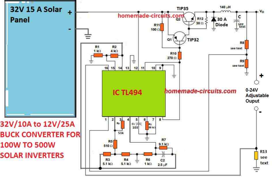
The example above shows a simple yet extremely handy, precision 5 V buck converter equivalent for the XL4015.
Here, it shows a solar inverter buck converter application, which can be adopted for any other desired DC to DC converter purpose.
The use of TL494 ensures that the design will not get obsolete easily and the replacement for the IC will be readily accessible whenever required.
Here too, an error amp feedback loop determines the output current by setting up the potential divider network built around R8/R9.
The current can be adjusted by tweaking the R13 resistor appropriately.
R13 = 0.2/Max Current Limit
Another great advantage of using the above discretely built buck converter is the output current level, which is not limited to 5 amps, rather could be upgraded to much higher levels simply by upgrading the transistors, the inductor wire thickness and the R13 resistor value.


Questions & Answers
Hi, how are you doing sir
Sir I have a 40V 20A buck converter, will it be capable for 39.3V 9A input?
Hi Tunji,
I am good, thank you!
Yes, that’s perfectly OK. Lower V/I is ok, higher than 40V/20A is not OK.
Good to hear sir,
But is there a way for me to reduce the voltage before the buck converter?
Sure Tunji, here is the regulator circuit which you can try before the buck converter:
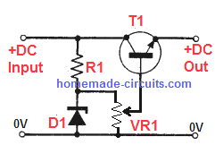
The zener diode decides the maximum output voltage range.
VR1 value can be a 10k preset
R1 can be 1K
T1 can be any 30 amp Darlington transistor
Hi sir,
If I wanted to use IRLZ44N MOSFET transistor in place of Darlington transistor is it possible, and I need pin connection hint(for that circuit you recommended)?
Hi Tunji,
I guess you are referring to the last circuit, in that case no, MOSFET cannot be used to replace the shown transistor configuration….
I’m actually referring to the circuit below sir, which common 30A transistor can you recommend sir
You can replace the BJT with a MOSFET, but the source side of the MOSFET might drop upto 4V, while the BJT emitter side will drop only 1V.
OK, thank you so much sir
You are welcome Tunji!
Thank you so much sir for the quick response.
You are welcome Tunji!
Hi. I’m looking at the basic working schematic of the XL4015 buck converter. If I connect an external adjustable voltage to FB pin, say 0 to 10 volts, will the output voltage also change from 1.25 to 11.25 volts (10 + 1.25)? What should be the values of R1 and R2 for such circuit to work? My goal is to adjust the output voltage of the XL4015 via an external voltage source, such as output of an op-amp. Thanks for all your replies.
Hi, I don’t think the FB will work with a varying voltage since it is designed to cut off at a single fixed threshold, as determined by the values of R1, R2 resistor. The R1, R2 values are adjusted to generate 1.26V at FB when the desired max output voltage threshold is reached.
You are correct. My XL4015 module the same with the one shown in this article just arrived. I tried connecting varying voltage to FB and it just did not work. Anyway, I’m struggling to make an adjustable voltage supply up to 12 volts and capable of about 3 amp wherein the output voltage is controlled by another varying voltage. I bought LM317 and XL4015 modules to tinker with but no success so far.
You can do one thing, use an LDR in place of R1, and an LED with a series resistor, with the LM317 output.
Enclose the LED and the LDR inside a light proof box.
I see. Then the brightness of the LED will change the resistance. I will consider that as a last resort. For the XL4015, I actually tried connecting a varying voltage between + output and FB pin and the voltage does change. However the varying control voltage needs to be a floating supply.
Floating supply, meaning without the ground connected? That sounds strange, not sure how that may be working.
I have another question. Can a computer power supply be used on the 5v section along with an adjustable Vreg using a bypass transistor section to get a 3.65v to use as a source to top off LiFePo cells to test them before connecting them to build a DIY 12v battery? It seems workable to me.I would just need some way of limiting the charge current safely to not take out the power supply, other wise I would have to purchase a power supply that can be regulated.
Sorry, I did not understand what you meant by “using a bypass transistor section”? Do you mean an emitter follower transistor configuration to produce the 3.65V?
XL4015 Alternative (Equivalent Circuit)
In this circuit Q2 base and Emitter is shorting in my circuit.
where is Q2 in the above XL4015 circuit?
In TL494 circuit
Q2 Base and Emitter is shorted, and it is very heat
Q2 base emitter is not shorted there’s a 30 ohm resistor.
You can remove that resistor if you want.
The circuit was taken from the datasheet of the IC, so it has to be correct.
Does it use two transistors to reduce the resistance of the Rx resistor?
On one transistor 547, you can also do this by connecting the collector between R1 R2, but then you will need to use more resistance of the resistor Rx, with formula Rx = 0.6 / Current Limit – do I understand correctly?
The FB pin of the IC needs to be fed with a HIGH logic to initiate a shut down during a high current situation, the PNP transistor converts the NPN conduction into a high signal for the FB pin of the IC.
Yes exactly. I just previously worked with LM317, where the adjustment is controlled by ground for shutdown. In this case of LX4015, can the Rx and transistor 557 be connected to the output line, so that the emitter and base of the transistor are powered by the Px resistor for current adjustment?
OK, yes a single PNP can also work to provide a positive feedback to the IC. The connections would be as given below:
Emitter to the positive output line, collector terminating as the final positive output source.
Base connected to the collector line.
The current limiting resistor can be connected exactly in between the points joining the collector and base of the transistor.
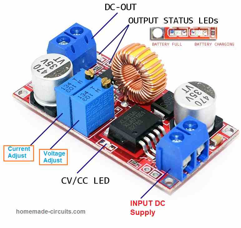
The picture of the buck converter above does have adjustable current limiting, so why are you adding it?
I have used these modules many times and they are current adjustable.
I have written the article with reference to the schematic of the IC which has no current control feature.
If you are saying that the module has a current control please specify how it is done? Let’s say we want to limit maximum output current to 1 amp, how can we adjust this?
Also please provide a link which specifically mentions about the current control feature of this IC. Please remove the https while providing the link.
Hi Swagatam,
Here is the link to an article about this circuit.
I have also added a circuit that can control the current for mppt applications, I will post for you soon.
Regards
Petrus Bosman
Thank you Petrus for the information,
I guess I posted the wrong module image, I have replaced it now with the module having a single preset, without the current control feature.
So as I mentioned earlier, the above article is intended for XL4015 modules which does not include a current control feature.
Thank you sir,
You can post the circuit as I show in the link for the schematic with the current limiting included.
I will post the mppt add on circuit soon.
Regards
Petrus Bosman.
Hei, friend I’m wondering if I could use this article in my study,
could u please give me written permission to use this article
best regard
Fouad
Hi Fouad, You can use the above article in your study. You can use this comment as the written permission.
No problem Petrus, Actually I removed the previous link because I cannot post other website links. But i will surely post your MPPT design if you provide it to me.