The purpose of this paper is to detail a variable dual lab power supply circuit which has an adjustable range from 3V, 5V, 6V, 9V, 12V, and 15V or even more at an output current rate of 1 amp.
Written By: Dhrubajyoti Biswas
The Dual Power Supply Concept
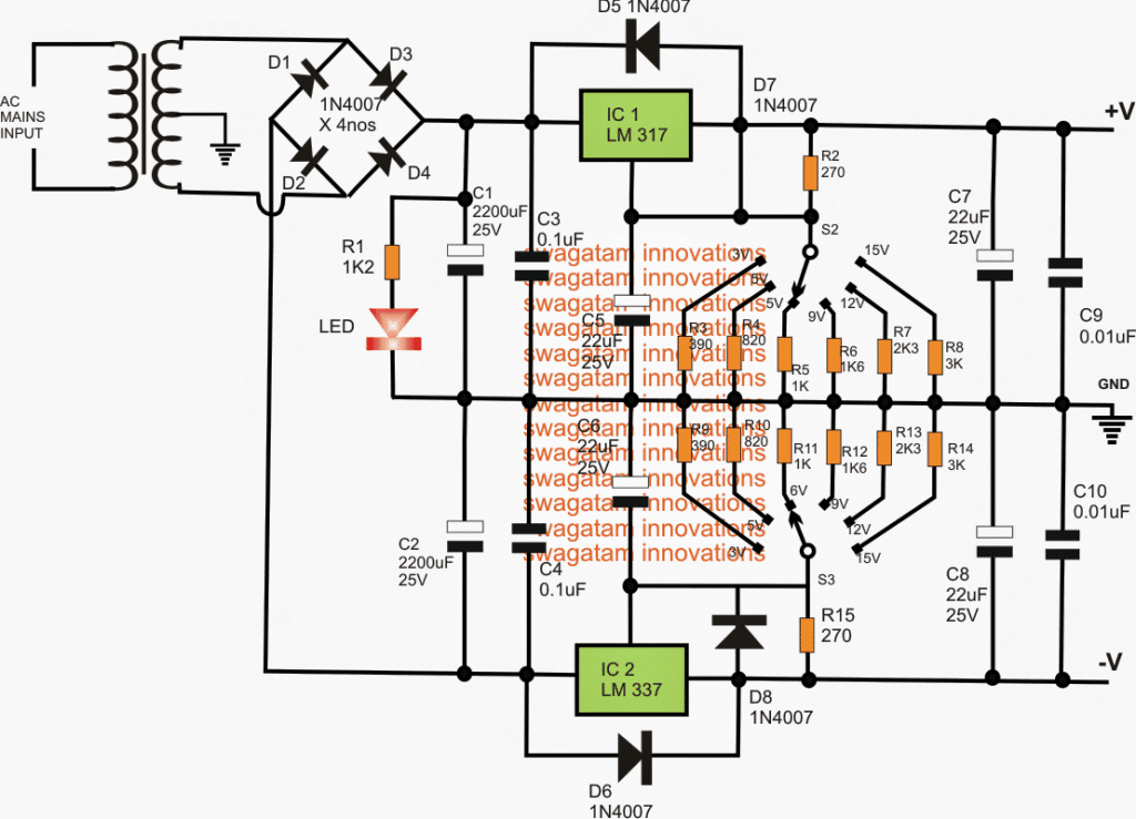
In regard to positive volt it is preferable to use IC LM317 [-3V,-5V,-6V,-9V,-12V,-15V at 1A] and use LM337 as the negative volt. The voltage can further be controlled by S2 [+Vout] and S3 [-Vout]. The size of the transformer is set to 2A and furthermore the IC enables holding the heat sink.
However, for this development we would like to develop a dual positive power supply, ground and negative so as to experiment it in different circuits.
In addition, we can also experiment OP-amp IC – LM741, which uses the power supply voltage of +9 volts and -9 Volts. Even when we use tone control circuits or preamplifier circuit, they will use voltage supply of +15 volts and -15 volts.
Nevertheless, the circuit that we design here will be useful because a) The circuit has the capacity to enable positive voltage and even negative voltage [at 3 volts, 5 volts, 6 volts, 9 volts, 12 volts, 15 volts respectively keeping the output of the current under 1.5 amps; b)
The circuit is best to use with rotating selector switch, which will give the freedom to select the level voltage. Moreover, you won’t require any voltsmeter to measure the voltage of the output; c) The circuit is simple and the IC used for it LM317 and LM337 are cheap and can be easily procured from the market.
Circuit Diagram
How the circuit works
In this dual variable power supply circuit IN4001 – D3 and D4 diode acts as the full-wave rectifier. The waveform is then filtered to ease the capacitor C1 (2, 200uF).
Then the input of LM317T (ICI) acts to regulate the IC in a positive mode. Furthermore, it also adjusts the voltage of 1.2-37 volts and enable provision of maximum current output of 1.5 amps.
Point to Note
- The output of the voltage can alter because of the value of change in Resistor R2 and further alters R3 to R8. This is accomplished by S2 selector switch and you can choose the resistance as per your need, in order to gain the voltage level from 3, 5, 6, 9, 12 and 15 volts.
- The C2 (22uF) measured with high impedance and further reduces to transient on the output of ICI-LM317T.
- The C3 (0.1uF) capacitor is used when IC1 is installed keeping distance from C1.
- The C5 (22uF) capacitor, before being amplified and as the output of the voltage goes up acts as ripple signal.
- The C9 capacitor is used to low down the ripple in the output.
- The D5 and D6 diode (IN4001) in the circuit is used to protect IC1 from the discharge of C7 and C5, in situation when the input is in short circuit.
- With regard to the negative mode, it follows similar principle like that of the positive mode. Here, D1, D2 are the rectifier diodes in a model where the rectifier is in full wave. The IC IC2-LM337T is regulated by negative DC.
Aforesaid is the process to develop an adjustable dual power supply. However, if you need the voltage to be variable in nature [for instance, 4.5V,7.5V,13V et al], simply add the VR1 in IC1-LM317 and IC2- LM337 pin.
If a rotary switch is used instead of a potentiometer, as shown in the diagram, make sure to use a rotary switch having a "make before break " feature which will ensure that while operating the rotary switch, the output does not swing to the maximum voltage level during the split second transitional disconnection of the switch contacts. The "make before break" feature is specially designed to prevent such situations from occurring.
Calculating the Resistor Values:
The values of the various fixed resistors could be calculated either through this calculator software or using the following formula:
VO = VREF (1 + R2 / R1) + (IADJ × R2)
Where R1 = 270 ohms as given in the diagram, R2 = the individual resistors connected with the rotary switch, and VREF = 1.25
For most applications IADJ could be simply ignored since it's value will be too small.
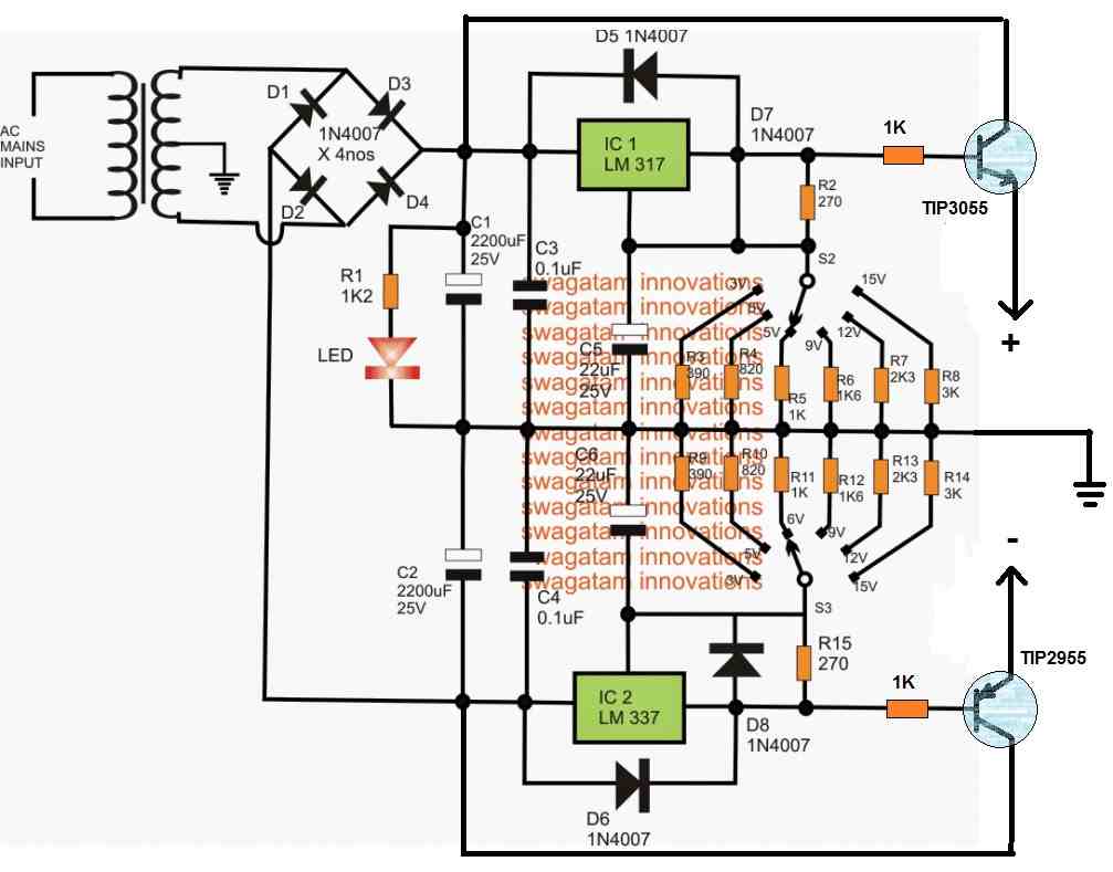
LM317 Symmetrical Power Supply with Current Boost
The above symmetrical LM317 dual power supply circuit can be further upgraded into a high current symmetrical supply, using the following configuration. The current boosting is delivered by the power transistors TIP3055 and TIP2955.
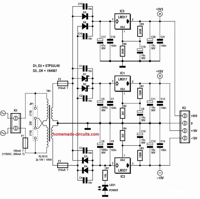
Another LM317 Simple Dual Power Supply Circuit
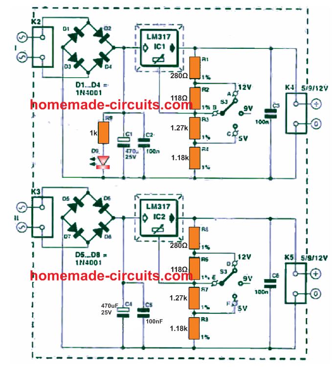
The diagram above shows how a simple yet higher versatile, adjustable dual power supply circuit could be built through just a couple of LM317 ICs. The circuit will produce an adjustable dual supply of 12V, 5V, and 9V
It means, an effective variable dual supply output could be achieved by using readily available IC like LM317, which is very easily accessible in any electronic market.
The design employs a couple of identical LM317 variable regulator circuits driven through separate bridge rectifiers and AC inputs from the transformers.
This allows us to join the + and - of the two supplies to create a dual supply of our own choice as per specific requirements.
Considering that it should be achievable to adjust the output voltage to 3 variable ranges, the voltage regulator applied is a kind whose output could be fixed using a handful of resistors, as shown in the circuit diagram. The output voltage is determined using the formula
Uout = 1.25(1+R2/R1) + IadjR2, in which 1.25 signifies the reference voltage of the IC, and ladj indicates the current moving through the 'ADJ(ust)' pin of the device towards ground.
The IC LM317 has internal compartaors, which constantly analyzes portion of the output voltage, fixed by resistive divider R1/R2, with the reference voltage. In the event that Uout is required to be higher; the comparator output is switched high which forces, the internal transistors to conduct harder.
This action decreases the collector-emitter resistance, causing a boost in the Uout. This set up guarantees a practically constant Uout. Practically , the value of Iadj falls between 50 µA and 100 µA. Due to this lower value, the factor Iadj R2, could typically be removed from the formula. Therefore, the refined formula
Uout = 1.25[1+(1270+1280)280] = 12.19 V.
Precision Dual Voltage Power Supply
This circuit has the benefit over the standard 2-resistor voltage divider where the voltage ration V:V does not rely on the current flowing from it. The ratio of resistances R:R1 determines the voltage ratio.
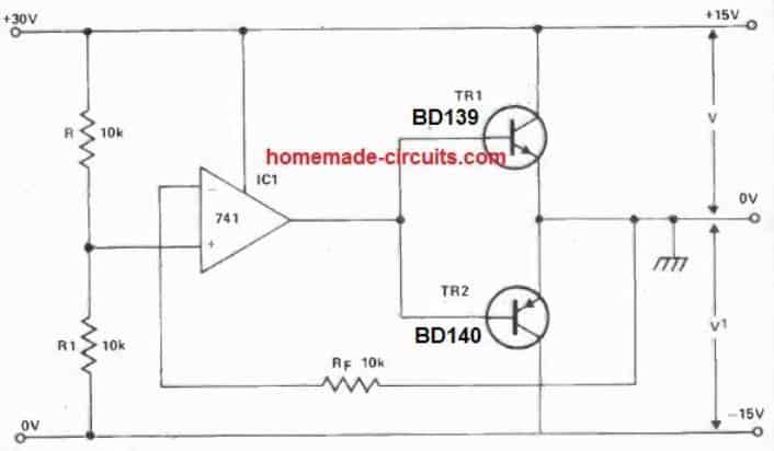
The OP-AMP identifies any change in this ratio via Rf and quickly executes the correction. The actual voltages utilized will be limited by the upper and lower operating voltages of the OP AMP. The circuit shown was developed to deliver +15 V, -15V dual supply, specifically for the operational amplifiers.
Balanced Power Supply using LM324
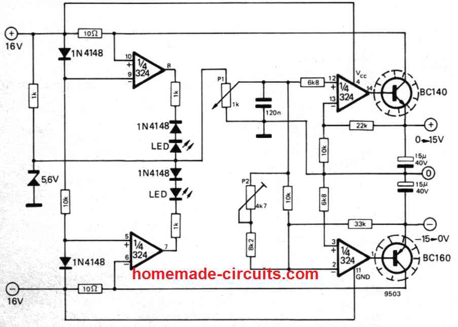
This stream-lined balanced power supply utilizes the 4 opamps from one LM324 IC. These are employed to stabilize the output voltage and also to control the output current. The current limiter circuit is defined at 60 mA and consists of lowest number of parts.
It has to be taken into account that under certain situations it might appear that the (input) power supply of only ±16 V is actually very low. However, the highest output voltage is determined by the specifications of the IC employed. It is far from safe to raise the input supply voltage; any kind of rise in the voltage could destroy the IC, depending on its maximum input voltage tolerating specifications.
A 5.6 V zener diode is employed for fixing the reference voltage. The zener value is not really crucial; if it is small, the output voltage is going to be a bit lower.
P1 works like the voltage adjustment pot simultaneously for controlling both the +15 and -15 supplies. Using P1, the reference voltage gets broken down and is given to the + input pinout of the (upper) opamp.
This particular opamp manages the positive output voltage by governing the base current of the series regulating transistor (BC140). The stabilization of the output voltage is influenced through a negative feedback loop through a voltage divider network composed of the 22 k and 10 k resistors.
The regulation of the negative voltage tends to be relatively more complex. The + input pinout of the lower opamp is coupled to the zero voltage '0', by means of a 6k8 resistor.
The reference voltage is employed through control pot P1 along with various other parts with the - input pinout. The negative output voltage is well balanced with respect to the positive reference voltage using the voltage divider `see -saw' network established through the 33 k and 10 k resistors (that are bridged together through a trimming circuitry).
Trimming preset controller P2 cancels out the impact of small tolerances in the circuit elements, and P2 can be tweaked to balance the positive and negative output voltages. Over Current safety is achieved by the a couple of leftover opamps in the IC.
In case the voltage difference across one of the 10 ohm resistors becomes greater than 0.6 V, the reference voltage is going to decrease to zero and, as a result, the output voltages also reduces along with it. Simultaneously the LED's illuminate to show that the protection feature of the circuit is working.
Another Simple 3V to +15V, -15V Dual Power Supply Circuit
The following figure shows another simple dual power supply circuit which can be customized to get any dual voltage between 3V and 15V. THe
By appropriately changing the values of the resistors R2, and R4 resistors it may be possible to alter the output from anywhere between 3V, 4.5V, 6V, 9V, 12V, 15V dual supplies.
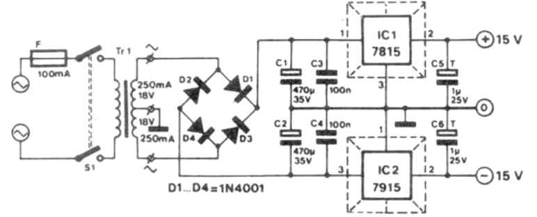
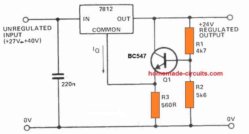
For a fixed dual power supply you can use the following configuration. Here we can see that, for the positive supply the IC 7812 is used, and for the negative supply, the IC 7912 has been used:
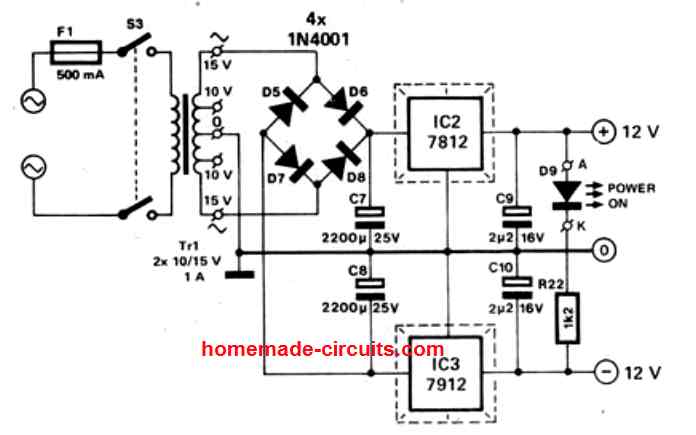
Dual Power supply circuit using IC 7815 and IC 7915
LM317 Dual Power Supply Circuit with Opamp Adjustable Output
The following variable dual power supply again uses the ICs LM317 and LM337, however it has an interesting way to adjust the output symmetry using an opamp based circuit.
The idea was tested and contributed by Mr. Constantinos Mermygas
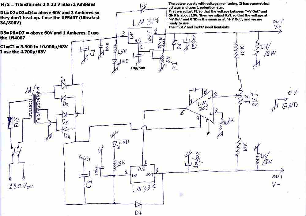
How to Use
First we adjust P1 so that the voltage between +Vout and GND is around 15V. Then we adjust RV1 so that the voltage across the -Vout and GND is same as +Vout, and we are ready to use.
The ICs LM317 and LM337 need heatsinks.

Questions & Answers
What is the secondary voltage of the transformer in the first diagram?
Thank-you,
It can be a 18-0-18V or 20-0-20V 1 amp…
Hello, it’s obvious where it goes but D7 symbol is missing from the first circuit diagram.
It is mentioned in the article : “- The D5 and D7 diode (IN4001) in the circuit is used to protect IC1 from the discharge of C7 and C5, in situation when the input is in short circuit.”
Thank you for pointing out the mistake. D7 is actually mistakenly mentioned, it should be D6 instead. So it is D5 and D6 which are used to protect the IC from input short circuits.
Hello Sir,
What is the secondary voltage of the transformer in the “Adjustable 3V, 5V, 6V, 9V,12V,15V Dual Power Supply Circuit” diagram, please? Also, the diode D7 must have been forgotten to draw in the diagram.
Thank you,
vr
Selahattin
Hello Selahattin, since a LM317/337 are used which cannot handle more than the 1.5 amps, therefore the secondary of the transformer could be rated at less than 1.5 amps. D7 is mentioned nowhere in the article.
Good evening Sir . I very often go through your page homemade -circuits . Few days ago I have visited a circuit related to smps using transistor mje13005 . But I am sorry to say that the circuit is providing very weak current. The circuit which I have assembled is capable of providing only few milliamperes of current. The same thing happened previously with other circuits. Kindly help me in building a smps 12 volt 1 ampere from 230 volt ac line voltage supply . I wish to make a led power supply with the same in low price.
Hi Shantanu, if you want a reliable 1amp 12V smps then you can try the following design:
https://www.homemade-circuits.com/how-to-make-simple-12-v-1-amp-switch/
Very very good circuit, I really understood all thanks for all the diagrams may God bless you and give you more wisdom to analyze more circuit to us I hope to see more circuit diagrams analysis from you. Thanks
Thank you very much, and glad you liked my work!
Mr Swagatan
At the beginning I would like to say THAT GOD WILL BLESS YOU your article are really wonderful and educatoves
I would thank you alot if you may direct me to web site that over there it would be possible to find a plan for an home made epron programmer and reader,I need it for motor tuning of car ECU wiich is basically reprogramming the epron
I would be awfully thankful if you may help me with this matter
Thank you for your collaboration
JEOVANNY VITERI
Thank you Mr Viteri, I am sorry I do not know much about EPROMs and how they are programmed, so I can’t help you in this regard.
Good day Swagatam, I would like to share with you the integration of the Bench Top Power Supply for your advice. As discussed, I used the diagram suggested by you and other diagram where the transistor were added to the LM317 and Lm337 for increasing current. I would really like to hear your advice to this respect but this plataform doesn’t allow me to send the picture.
Hi Jorge, yes unfortunately image upload facility is not available in this website by the user, but no problem, you can explain the problem through comments, I will try my best to understand it and solve it for you…
Hello, I really love this idea with the switch, but I was thinking to add the 2N3055 and MJ2955 at each LMXXX IC to increase the output current. Has you designed one with this option cause sometimes 1 amp is not enough but maybe 3 or 4 amps. I would really love to hear about this. I am a Hobbyist currently working in my new Workbench Power Supply.
Thanks
Hi, yes you can add an outboard transistor for increasing the current, you can read the following article for more info on the same:
LM317 with Outboard Current Boost Circuit
You can think about designing bench power using discrete parts without ICs, as discussed below:
Make a Workbench Multimeter With the IC 741
Pls swag,I need a very efficient circuit that can stepdown 48v to 12 voltage.I want to use it to power a microcontroller board.
Hi Joseph,
you can try the following concept:
https://www.homemade-circuits.com/5v-pwm-solar-battery-charger-circuit/
sir i hope am not disturbing you but am a little bit confused if i change the lm317 in the circiut to lm196 or lm396 what ic am i going to use to replace LM337
yes that may not be possible, because it seems there’s no negative complementary IC for LM196
sir can i use lm196 or lm338 for both ic to get high current up to 10amps or are there any other ic that can replace the ones in the diagram for higher current up to 10amp
Marvin, you can use LM196 or LM396 for getting upto 10 amps by adding adequate heatsinking to th IC.
sir what change do i have to make to get 6 or 7 amps from the circiut will i have to wire more lm312 ic in parallel at both sides
Abioye, adding more ICs in parallel can be complex, instead you can try the following alternative design
https://www.homemade-circuits.com/0-to-50v-0-to10amp-variable-dual-power/
Sir please am doing a project on a DC regulated power supply with voltage of 2v,6v and 9v…
I find this circuit diagram very useful but am having some doubt’s about excluding other resistors in the circuit and use the necessary ones I require.
Please its an urgent project
Flynn, you can remove the switching resistors which are not required…
I found it is important to use a rotary switch that connects the next pole before disconnecting the first one. Otherwise as you rotate the control there is a brief moment where it is open circuit. This will result in a high voltage spike on the output. Possibly damaging the connected device. With a “ make before break” type there will be a brief voltage drop as you rotate. Not normally an issue.
Thanks for pointing out the issue, I will update the info in the article soon.
sir, with a center tap 12-0-12 transformer will it be possible to get two positive 12v from each side?
if yes, kindly help me out with the circuit diagram
if no, can I use the negative (-12v) of the center tap transformer to supply circuit that requires +12
sir what I really what to do is to simply two separate circuit (that is 1. the egg Turner timer circuit and 2. the temperature control circuit) with the same center tap transformer
Patrick, for getting two separate +12V lines you simply need to bifurcate one +12V from a bridge rectifier output into to positives lines using two separate diode. that's…a center tap is not required for this.
the ground will be common for both these +12V lines
Sir,
In circuit diagram ic LM317 output pin
direct short with Adjust pin
thanks Ubaid, it's a drawing mistake, there should be a diode there instead of a short
Sir Swagatam Majumdar !!!
i have simulated this circuit but it is not giving proper output voltages.
i.e when rotatory switch is connected with 3k resistance ,it gives 21.43 voltages
when rotatory switch is connected with 3k resistance ,it gives 21.34 voltages etc what should i do.
Errors are expected in Simulation…have you made it on Hardware???
you are welcome!!
Thanks sir.
i will give it a try very soon.
Thanks for your informative posts.
Sharing is Caring 🙂
Asif, I have not made it practically, but the design looks very obvious and straightforward, so there's no harm in building it practically and tweaking the results with some trial and error….there's nothing in the design that might blow of or burn during the testing process…