The increased number of complaints from the readers regarding burning LEDs associated with my earlier posted transformerless 1 watt LED driver circuit, compelled me to solve the issue once for all. The power supply section of the circuit discussed here remains exactly identical to the previous configuration, except the inclusion of the "switch ON delay feature" which has been exclusively designed by me and added in the circuit for rectifying the burning LED problem (hopefully).
Warning: All the circuits I have explained below are not isolated from mains AC and are therefore extremely dangerous to touch in an open and powered condition. A high level of safety precaution is recommended while handling these circuits.
Suppressing In-rush Surge in Capacitive Power Supplies
The complaints that I kept on receiving were undoubtedly because of the initial switch ON surge which kept destroying the 1 watt LEDs connected at the output of the circuit.
The above problem is pretty common with all capacitive type of power supply, and the problems has created a lot of bad reputation to these types of power supplies.
Therefore normally many hobbyists and even engineers opt for lower values capacitors fearing the above consequence in case larger value capacitors are included.
However as far as I think, capacitive transformerless power supplies are superb cheap and compact AC to DC adapter circuits which requires little effort to build.
If the switch ON surge is tackled appropriately, these circuits would become spotless and could be used without the fear of any damage to the output load, especially an LED.
How Surge is Developed
During switch ONs, the capacitor quite acts like a short for a few microseconds until it gets charged and only then it introduces the required reactance to the connected circuit so that the appropriate amount of current only reaches the circuit.
However the initial few micro second short condition across the capacitor inflicts huge surge to the connected vulnerable circuit and is sometimes enough for destroying the accompanied load.
The above situation can be effectively checked if the connected load is inhibited from responding to the initial switch-ON shock, or in other words we can eliminate the initial surge by keeping the load switched OFF until the safe period is reached.
Using a Delay Feature
This can be very easily achieved by adding a delay feature to the circuit. And that's exactly what I have included in this proposed surge protected hi-watt LED driver circuit.
The figure shows as usual an input capacitor, followed by a bridge rectifier, until here everything's pretty common capacitive power supply.
The next stage which includes the two 10 K resistors, two capacitors, transistor and the zener diode form the parts of the important delay timer circuit.
When power is switched ON, the two resistors and the capacitors restricts the transistor from conducting until both the capacitors get fully charged and allows the biasing voltage to reach the transistor base, illuminating the connected LED after a delay of about 2 seconds.
The zener is also responsible for prolonging the delay for two seconds.
The 1N4007 diode across one of rhe 10K resistors and the100 K resistor across one of the 470uF capacitors helps the capacitors discharge freely once the power is switched OFF so that the cycle can repeat enforcing the surge protection into action on each occasion.
More number of LEDs may be connected in series for increasing the power output, however the number may not exceed 25 nos.
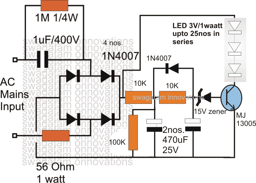
Circuit Diagram
UPDATE: A more advanced design is discussed in this zero crossing controlled surge free transformerless power supply circuit
The videos below show the LEDs illuminating after about a second on power switch ON.
Complaints From the Readers (Resistors burn, transistor becomes hot)
The above concept looks great but is probably not working well with the proposed high voltage capacitor power supply.
The circuit has to be researched a lot before it becomes completely free from troubles.
The resistors in the above circuit are unable to withstand high current requirements, same is true for the transistor which also becomes quite hot in the process.
Finally we can say that that unless the above concept is thoroughly studied and made compatible with a capacitive transformerless power supply, the circuit cannot be put into practical use.
A Much Robust and Safe Idea
Even though the above concept failed to work it doesn't mean the high voltage capacitive power supplies are completely hopeless.
There's one novel way of tackling the surge issues and making the circuit failproof.
It's by using many 1N4007 diodes in series at the output or in parallel to the connected LEds.
Let's have a look at the circuit:
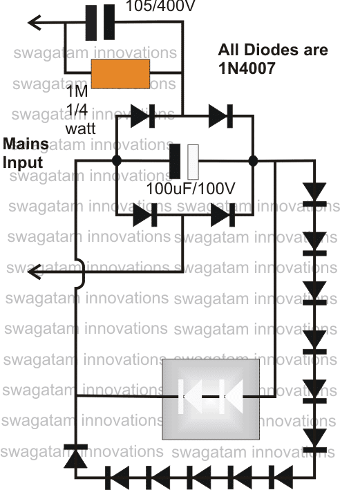
The above circuit is yet to be tested for many months, so these are still early days, but I don't think the surge from the capacitor will be high enough to blow the 300V, 1 amp rated diodes.
If the diodes remain safe so will the LEDs.
More diodes may be put in series for accommodating more number of LEDs.
Using a Power Mosfet
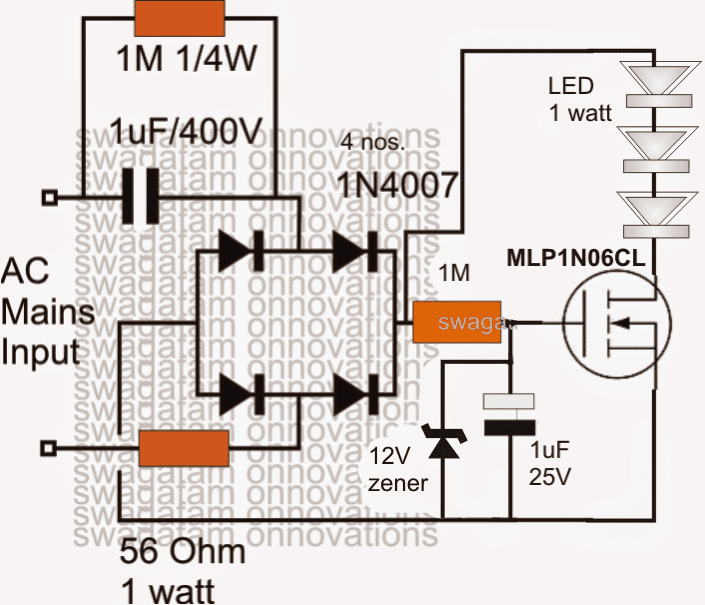
The first circuit attempt which seemed to be vulnerable itself to surge causalities can be effectively remedied by replacing the power BJT with an 1 amp mosfet as shown in the following diagram.
The mosfet being a voltage controlled device, here the gate current becomes immaterial and therefore a high value 1M resistor works perfectly, the high value makes sure that the resistor does not heat up or burn during the initial power switch ON. It also facilitates a relatively low value capacitor to be used for the required delay ON surge suppressing feature.
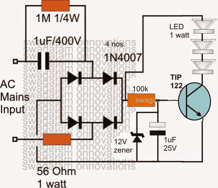
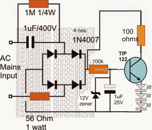
A little investigation revealed that the high voltage transistor in the first diagram is actually not needed, rather it can be replaced with a high current Darlington TIP122 transistor as shown in the following diagram.
The high voltage surge from the capacitor becomes ineffective against the high current specs of the transistor and the LEDs and no damage is caused to them, in fact it forces the high voltage to drop to the specified allowable safe limits of the LEDs and the transistor.
The TIP122 also allows the use of a high value base resistor thereby making it sure that it does not become hot or blow off in the course of time, it also allows the inclusion of a low value capacitor at the base of the transistor for implementing the required delayed switch ON effect.
Using a Power BJT
The above design further improves in terms of safety and surge suppression when used in a common collector mode, as given below:


Questions & Answers
Sir, gud ngt. I want to know that I have a filament type 3v torch bulb which were used in old torches and I want to run it on 220v ac with transformer less circuit how I do it.pls give me suggestion.will it run or it will burst
Atul, you can try the following circuit, but use only 5 diodes at the output instead of the shown 12 diodes
Required transformer less power supply.
Input 230 Volt
Out put 12 Volt DC.
0.1Amps
You can refer to the following article for all the details.
4 Simple Transformerless Power Supply Circuits Explained
For 100 mA current change the 105 capacitor to 2uF/400V
What is the maximum current it can handle?
I believe it is only ~70mA.
If so will adding 2 more 1uF/400 as parallel increase it to 210mA?
Does this circuit not require filter capacitor?
If required what will be the ideal value of the capacitor?
It is actually only 50mA that can be achieved from a 1uF capacitor practically. For higher current you can try a triac based ciruit as I have explained below:
https://www.homemade-circuits.com/high-current-transformerless-power-2/
you can use a 1000uF/50V as the filter capacitor.
Thank you sir
how to modify the TIP122 based circuit for 5V,1A DC power supply ??
please reply …
don't use the tIP122, use the following one instead:
https://www.homemade-circuits.com/2016/07/scr-shunt-for-protecting-capacitive-led.html
replace the zener with 5V 1 watt
hi can i use this project to replace the transformer from pc speakers
the transformer is 9v ac thanks
Hello sir
If i use .2W 25 LEDs instead of 1W LEDS what are the modifications suitable for that circuit?I talk about circuit which was made using Tip122 transistor.
Thank you.
MOV will not last a lightning strike, in fact no device will control a lighting bolt except a well earthed rod.
An MOV and a NTC can be used for controlling 220V switch ON surges only…any 330V MOV will do the job, and any 5 ohm type NTC will be great.
If i use MOV and PPTC devices series and parallel with this circuit.I can avoid both of these problems know.If it is ok,Please give me the proper ratings of this two devices which is suitable for my circuit.
Thank you,
you can connect all 50 LEDs in series with the proposed circuit….iy will be fine, no changes are required
no this circuit is not designed to suppress lighting bolts.
I mentioned LED value as a 0.2W.I think you got that value correctly.
Thank you.
another 2 questions,
1.If i need to use 40 or 50 .2W LEDs in circuit. What is the best option for me?
2.Do these circuits suppress lightning surges??
Hello Pushpike, you can use the last circuit which is shown in the above article without any modifications
just change the 56 ohm resistor to 10 ohm resistor.
Hello Swagtam,
I am working on making 2 in 1 LED bulb where there will be 12w normal light will be there and 1w to 3w Night light will be there in the same bulb.
But, I need your help to guide me how I can achieve this. When this light will be first switched on then it will glow as normal 12w LED Bulb, once it is switched off for 2 seconds and switched On this will glow as night lamp with 1w LED.
I am thinking to use flip-flop electronic circuit to achieve the above. Please give me your suggestion.
Hello Nitrous, a flip flop could make the design unnecessarily complex, I think it can be implemented using an ordinary SPDT switch…the center pin goes to the (+) of the input supply… out of the two outer pins, one connects with the LED (+) through a calculated 12W resistor, while the other pin connects with the LED (+) through a calculated 1 watt resistor.
you are welcome shams!
Dear, Thanks for this fruitful article. I made this ckt. It's a good ckt but 1uf capacitor become very hot so I leave this ckt and searching better one. again thanks a lot.
Nope, for 10 watt LED you will strictly require an SMPS
what changes to be made for connecting 6 1w led
No, this circuit is not suitable for LeDs over 1 watt
Dear Mr Swagatam Ji, One the simplest thing I fail to understand by seeing the circuit given by you for 1watt powersuplly(transformer less) with surge protection that you have used only 1microfrad 400v capacitor and as far as I calculate it can only give 106 ma of current with a input main of 230vac 50hzs so at the output stage how we can gat 350ma of current to light 1watt LED with required brightness. Since I am new member and we're just reading your posts very interestingly since last one month I wanted to get the knowledge from you first because I am really interested in making few led projects of my own.
That's correct, but that can be compensated by using three 1 watt LEDs in series, 3 would provide a light equivalent to a single 1 watt LED, although you may have to spend 2 extra LeDs, the circuit will be free from heatsinks, current controllers etc.
please feel free to ask everything you may be interested in, in fact i may already have all the tutorials you may be looking for.
dear i did not get ur point clearly about fan dimmer circuit.How can i incorporate it with above last circuit?
dear, see the second diagram in the following article, the wiring details are clearly shown there:
https://www.homemade-circuits.com/2012/11/using-fan-dimmer-for-controlling-led.html
Dear i have tried ur last circuit with One pcs of 105uf instead of 3.3uf capacitor with MJE13005 and zener 15v for five 1watt LED in series.But still MJE13005 and 56ohm resistance are getting so much hot.For over come this problem i used 200k instead of 100k but result is negative.Also brightness is decreased after use of 105uf capacitor than 3.3uf.What can i do now pls help me.
Dear you are asking the same question again, please see the previous comment for the answer.
The best solution is to try the second design as given in the following article:
https://www.homemade-circuits.com/2012/11/using-fan-dimmer-for-controlling-led.html
Dear i have tried ur last circuit with 3.3uf capacitor, MJE13005 and zener 15v for five 1watt LED in series.But MJE13005 and 56ohm resistance are getting so much hot.I think it will burst out if i continue.Also other parts are remain in normal condition except MJE13005 and 56ohm resistance during running.So pls give me solution urgently.
Dear, increasing capacitors will not help to increase brightness rather it will make the circuit more vulnerable to surge currents and heat….if around 90 LEDs are used only in that case increasing capacitor value can be safe for increasing brightness of the LEDs.
You can probably try a fan dimmer switch unit after the 3.3uF capacitor and connect the LED through a bridge as shown in the example circuit at the bottom of this article:
https://www.homemade-circuits.com/2013/11/treadmill-motor-speed-controller-circuit.html
Dear how many capacitor i used 1 or 2 in series for optimum brightness of the LED?Also is this circuit is harmful for inverter(When main is absence)?
No, increasing capacitors will not help to increase brightness rather it will make the circuit more vulnerable to surge currents….if all 90 LEDs are used only in that case increasing capacitors in parallel can be safe for increasing brightness of the LEDs.
Dear if i use 13005 transistor instead of Tip 122 then it will worked? also if i use 2.2/2.5/3.3uf capacitor instead of 1uf then what have to changed in this circuit? How many LED can be driven by using this 2.2/2.5/3.3uf capacitor for proper brightness?Actually i want to drive 4/6/8/10/12 sets of 1 watt LED in series by this circuit.Pls help me by ur useful comments
Dear Saeed, yes surely you can try MJE13005, and also try using higher value capacitors instead of 105/400V, but make sure the LEDs are connected across emitter/ground of the transistor and a zener connected across base ground of the transistor….you can go on and connect upto 90 LEDs in series
Sir i made the last one circuit as you comment above i used 3 12v zener in series for 36volt but i used 10 LED in series it uses 3.6v but actually because of lack of current voltage get drop. so as you design last one circuit it is used for how much LED 1 watt in series? i used last one but i want ask what about 1st one circuit as in article you write some blogger is suffer resistor burning. is 1st one is suitable for my application as i want to use 20 no 1 watt LED in series.
you can try tweaking the output winding of the SMPS for getting around 70V at the output for your 20 LEDs.
Ashoke, you should use a 12V 1amp SMPS if you are intending to use 1 watt LEDs, for ultimate safety and long life….capacitive supplies will not provide optimal illumination and 100% protection