In this post I have explained regarding what's ripple current in power supply circuits, what causes it and how it can be reduced or eliminated using smoothing capacitor.
What's Ripple in Power Supply Circuits
In all AC to DC power supplies the DC output is acquired by rectifying the AC input power and filtering through a smoothing capacitor.
Although the process cleans the AC to almost a pure DC, a small content of unwanted residual alternating current is always left over within the DC content, and this unwanted interference in the DC is termed ripple current or ripple voltage.
This remaining unwanted AC content in DC mostly is due to inadequate filtration or suppression of the rectified DC, or sometimes due to some other complex phenomenon such as feedback signals from inductive or capacitive loads associated with the power supply or also could be from high frequency signal processing units.
The above explained residual ripple factor (γ) is technically defined as the ratio of the root mean square (RMS) magnitude of the actual ripple voltage to the absolute amount introduced in the DC line of the power supply output, and is normally represented in percentage.
Expressing Ripple Factor
There's also an alternative method of expressing the ripple factor, and that is through the peak-to-peak voltage value. And this method appears to be much easier to express and measure by using an oscilloscope, and can be much easily evaluated through an available formula.
Before we understand the formula for evaluating the ripple content in DC, it would be first important to understand the process of converting an alternating current into a direct current using rectifier diodes and capacitors.
Normally a bridge rectifier which comprises of four diodes is used for converting an alternating current into a full wave direct current.
However even after rectifying, the resultant DC may have a huge amount ripple due to the large peak-to-peak voltage (deep valley) still persistent in the DC. This is because the function of the rectifier is limited only upto converting the negative cycles of the AC to positive cycles as shown below.
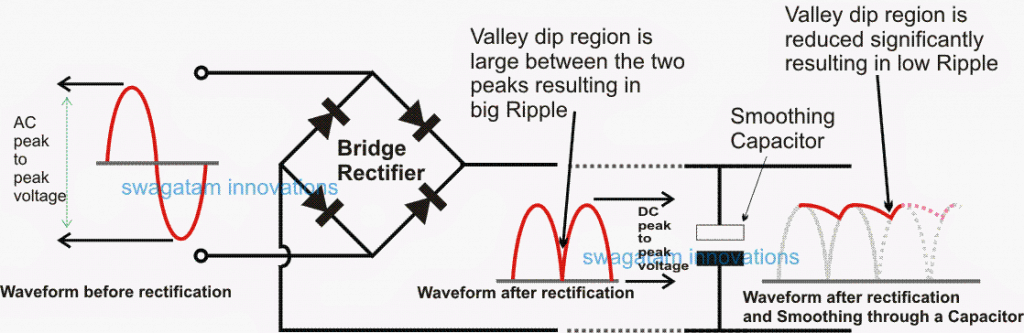
Diagram Showing Ripple Valley
The persistent deep valleys between each rectified half cycle introduces maximum ripple, which can be tackled only by adding a filter capacitor across the output of the bridge rectifier.
This large peak-to-peak voltage between the valleys and the peak cycles are smoothed or compensated using filter capacitors or smoothing capacitors across the output of the bridge rectifier.
How Filter Capacitor Functions
This smoothing capacitor is also called the reservoir capacitor since it functions like a reservoir tank and stores the energy during the peak cycles of the rectified voltage.
The filter capacitor stores the peak voltage and current during the rectified peak cycles, simultaneously the load also receives the peak power during these cycles, however during the falling edges of these cycles or at the valleys, the capacitor instantly kicks back the stored energy to the load ensuring the compensation to the load, and the load is allowed to receive a fairly consistent DC with a reduced peak to peak ripple as compared with the actual ripple without the capacitor.
The cycle continues, as the capacitor charges and discharges in the process in an attempt to minimize the difference of the actual peak-to-peak ripple content for the connected load.
Smoothing Efficiency Depends on Load Current
The above smoothing efficiency of the capacitor greatly relies on the load current, as this increases the smoothing ability of the capacitor proportionately decreases and that's the reason larger loads demand larger smoothing capacitor in power supplies.
The above discussion explains what's ripple in a DC power supply and how it can be reduced by inserting a smoothing capacitor after the bridge rectifier.
In the next article I have explained how to calculate the ripple current or simple the peak-to-peak difference in a DC content through the association of a smoothing capacitor.
In other words I have explained how to calculate the correct or the optimal capacitor value so that the ripple in a DC power supply is reduced to the minimum level.

Questions & Answers
i love this keep it up guys