In this post I have explained how to build a simple FM remote control circuit for toggling small AC loads such as lamps, fans etc using an ordinary FM transmitter circuit and a modified FM radio circuit.
This remote control system enables the user to get an ON/OFF control on any desired appliance, by simply modifying an existing radio into a remote receiver through a relay control circuitry.
Introduction
Remote control circuits are not so easy to build as they incorporate critical inductor stages and also, the components are difficult to procure.
However a simple homemade FM remote control can be made by modding your existing FM radio as the receiver part.
The transmitter can be simply made by assembling a few electronic components.
The two sections together can be used for controlling any electrical load remotely from any part of the house.
Making the FM Transmitter for the Remote Control Unit:
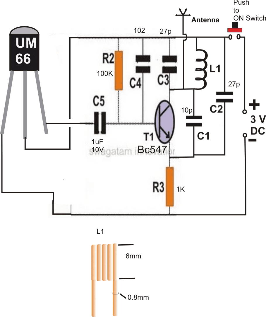
Parts List
- Resistors are 1/4 watt 5% CFR
- 100 k = 1
- 1 k = 1
- Capacitors
- Electrolytic 1 uF / 25 V = 1
- Ceramic 102 = 1
- Ceramic 27 pF = 1
- Ceramic 10 pF =1
- Ceramic 27 pF = 1
- IC UM66 = 1
- Inductor as shown in the diagram = 1
- 3 V Coin Cell = 1
- Microswitch = 1
The figure shows a very simple FM configuration using one transistor and few other passive components.
Here the inductor becomes the most crucial part and must be made carefully as per the given instructions.
T1 along with the pF capacitors and the inductor forms the RF stage and is responsible for the generation and transmission of the RF carrier waves.
Using a Music Modulation for Increasing Transmitter range
The section consisting of the IC UM66 and the electrolytic capacitor forms the modulating stage and injects the required modulation signals to the RF stage.
This helps to make the transmitted waves much stronger and travel up to longer distances.
Once the assembly of the transmitter circuit is done, its working should be confirmed by switching ON the transmitter and by verifying the received signals over the FM radio.
The reception should consists the music from the UM66 IC and should be received by the radio, loud and clear even from a distance of over 30 meters.
After finishing the construction of the transmitter, you need to assemble the Flip Flop circuit by soldering the electronic components as per the shown diagram.
This stage will be later on required to be integrated with the modified FM radio.
Formulas for Calculating FM Transmitter Parameters:
Frequency of Oscillation (fosc):
When the LC tank is connected to the BJT collector, the resonant frequency is:
fosc = 1 / (2π√(LCeq))
Where Ceq is the equivalent capacitance of the parallel combination of the tank capacitors:
Ceq = (C1 * C2) / (C1 + C2)
L: Inductor in the tank circuit
C1, C2: Capacitors in the tank circuit
Base Biasing:
Although we have not used a resistive divider network for the base of the BJT in our above design, the base of an FM transmitter is normally biased using a resistor divider network. The base voltage should ensure the transistor operates in its active region.
VB = (R2 / (R1 + R2)) VCC
Where:
R1, R2: Bias resistors
VCC: Supply voltage
Ensure VB > 0.6V (for silicon BJTs).
Feedback Capacitance for Oscillation (Cf):
Feedback to sustain oscillation is most of the times provided by a capacitor Cf, connected between the collector and the base. Its value decides the feedback strength. A typical range may be as shown below:
Cf ≈ 5 pF to 50 pF
Frequency Modulation (FM):
Frequency modulation could be achieved by varying the capacitance in the tank circuit, often using a varactor diode or simply by a trimmer capacitor:
Cvar = (ε * A) / d
Where:
A: Area of the diode junction
d: Depletion width (varies with applied voltage)
The modulated capacitance shifts the tank's resonant frequency.
Collector Current (IC):
For the oscillator to work properly, we have to ensure that the BJT transistor should provide sufficient gain. Collector current is calculated based on the base-emitter voltage:
IC ≈ β * IB
Where:
IB: Base current
β: Current gain of the transistor
How to Modify a FM Radio as a Remote Control Receiver for Controlling Electrical Gadgets
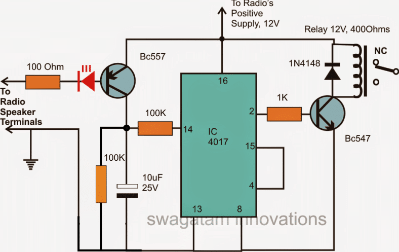
For this project you will need an ordinary FM radio for making the receiver/controller unit.
After procuring a FM radio, you will need to do the following modifications in it.
- Open the back cover of the FM radio to uncover the circuit of the unit.
- Now carefully, integrate the flip flop circuit to the speaker terminals of the radio. The connections won’t be difficult as everything’s shown in the diagram very clearly.
- The idea here is to use the reception audio from the radio speaker terminals and use it to activate our flip flop circuit and the relay.
- Switch ON the FM radio and tune to some vacant area where there’s no station available, and only the background “hissing” noise is audible.
- Adjust the volume control of the radio toward the maximum and you will find the LED light up, refine the adjustment until the LED just switches OFF.
- Now tune the radio to some station, without disturbing the volume control.
- You will find the LED flickering in response to the audio outputs.
- You will also see the flip flop responding appropriately and the relay switching randomly to the LED illuminations.
This concludes the procedures, your setting of the radio or the modifications of the radio is complete.
Testing the Remote Control Switching
Now switch ON the transmitter and once again tune the radio to the spot where it receives the transmitter music loud and clear.
That’s it, the setting of your home made remote control is complete.
Now as many time you click the transmitter switch, it will be received by the radio and the flip flop relay activated alternately.
The relay contacts may be wired to any appliance and may be controlled easily by your transmitter through mere clicks of its switch.
However the speaker of the radio will also make lot of noise and therefore to eliminate this you may just tear of the cone of the speaker so that it keeps silent, activating only the flip flop.


Questions & Answers
i need simple way to make a receiver and controller
It is my first time to comment here. And thanks for your great effort. Here are what I want to know.
I always tried to understand RF theory and what electromagnetic radiation is then to make RF remote control switch circuit. For example what if i wanted controlling my motor or make my LEDs lit wirelessly. If you have any idea it would be appreciated.
Thanks 😉
Thank you for commenting, appreciate it very much.
Yes, a RF based remote control can be built, and that’s exactly what I have tried to explain it in the above article.
It is probably the easiest way to create an RF remote control for controlling fans, LED lights, motor etc using an FM transmitter and a modified FM radio.
Let me know if you have any further questions.
Dear Swagatam,
Can I use 22pf instead of 27pf which is unavailable at my local.
Dear swagatam,
27pf is unavailable. Can I use 22pf.
with best;
yes it will work!
Hi Swagatam
What I understand from the above set-up:
a) When the push switch is pressed in the transmitter section, it will transmit the melody played by UM66.
b) The receiver will receive the signal and the coupled flip-flop circuit will convert the melody to a single pulse and latch the relay to an ON state.
My questions:
1) Why do we require to damage the cone of the speaker; why not simply remove it?
2) How does the flip-flop section gets reset in relation to the releasing of the push-switch in transmitter circuit?
3) Couldn't a transistor-based latch circuit be used in place of CD4017?
4) If I use more than one set-ups sharing a common power supply for the transmitters and then another common supply for the receivers, will they work? Of course, all of them would be tuned on different frequencies.
the plate is for prototypes built by wire connections, in a PCB the plate can be avoided if it's designed with un-etched grounded tracks surrounding the interconnecting thin tracks.
Do you think the receiver would work without the base metal plate for 2meters?
for just 2 meter range I think you should try the concept explained in the following article, both Tx, and Rx designs are explained
https://www.homemade-circuits.com/2013/10/make-this-simple-fm-radio-circuit-using.html
I have managed the triggering of the flip-flop.
Can you please recommend me some suitable FM receiver which:
a) have minimum components
b) could receive transmitter signal within 2 meter radius with shortest possible antenna
c) could be coupled with flip-flop circuit
I have not yet seen any reliable transistor based flip flop circuit which will trigger from a single ON/OFF source, therefore I won't recommend them, by the way which circuit are you referring to?
By transistor latch, I actually meant a transistor based flip-flop circuit. How would you couple it with the speaker wires?
Hi Abu-Hafss, Your a) and b) assumptions are correct.
the answers for the remaining questions are as follows:
1) By tearing the cone I only meant to indicate disabling of the cone vibration, you can do it anyway you feel, damaging the speaker is not necessary.
2) The 4017 will toggle its output sequence only when the 10uF cap is completely discharged and pin#14 receives a 0 voltage….and this can happen only once the transmitter button is released for some brief period of time.
3) a transistor latch will not toggle alternately unless it's also a flip flop circuit.
4) the set-up should work according to me without issues if the the relevant pairs are tuned to different stations.
i would like to give a try to this project & for that i expect ur support if i struck somewhere
& kindly let me what input we are provifing here
input is a music input from the IC um66
ty ☺
I'll try my best to help you
Hello a
Swagatam. I succeeded in making the transmitter and confess the reception is really clear , sharp and very audible and reception range is up to 50 meters while still maintaining the fidelity .
I am currently making the flipflop circuit and will let u guys know about my success
That's lovely Christian, wish you all the best…keep it going
I constructed the whole circuit but it's not working.. How do I detect what mistake is there? The relay switches on only when I short the two legs of the transistor. The fm board terminals gives negligible output through its terminals n led does not glow continuously. Please help me.
did you remove the speaker? do not remove it because it's coil's inductance will be required for amplifying the signal for the 4017 circuit.
if you don't want the speaker to be there you can connect any small inductor in its place
the LED must illuminate at maximum volume indicated by loud hissing on the speaker, next you must set it to a level as explained in the article.
if the LED is not illuminating then the transistor will not conduct
Sir wat is the number of turn of L1
Thanks and regards
it's shown in the diagram itself…
Fantastic!
I won't be using a relay. I plan to use an optocoupler to change polarity on a com port pin.
Thank you
yes that too would work nicely…thanks
Hi Swagatam,
I love this remote control circuit. I do have a couple questions.
1.) You show the receiver on 12v. Can it run on 5v?
2.) Can the sound on the receiver be recorded without interfering with the switching?
Thanks
Ralph
Hi Ralph,
yes 5v can be used if the relay is also selected at 5V
signal for recording can be picked across the speaker terminals, it will not interfere with the remote control functioning.
Hi swagatam, thanks for helping us with your circuit diagram, please i want you to help me with 5000 watt inverter circuit diagram using ferrite core transformer, which can power, air conditioner, electric iron, refrigerator etc.hope to hear from you soon, please uyo can send it to my email, imoudo37@yahoo.com Thanks.
Hi Imo,
you may please refer to the following link:
https://www.homemade-circuits.com/2014/07/5kva-ferrite-core-inverter-circuit.html
it's shown in the diagram, click the diagram to enlarge.
Pls give details of L1 coil in the first circuit
hi mr. swagatan , I had put a diode
rectifier in place of the LED, but I
put the LED, what happens is that
even lowering the volume of the radio
LED stay on(doesnt turn off) and when i test
with a channel fm the relay
dont turn on
…..one of the speaker terminals should be at ground level with the circuit and the radio.
If your speaker loudness is decreasing then it should also make the LED brightness lower proportionately, that should obviously happen.
Anyway connect a 100uF capacitor in series with 100 ohm resistor and then check by doing the procedures.
positive of the cap will go to 100 ohm and negative to speaker terminal.
By the way did you connect the circuit ground with the radio ground??
Hi swagatan 1 more time, my receiver is not working well,when i connect the input in the speakers i ear a buzzing's and the 100Ω resistor heats to much, could
help me figure out the problem?
Hi Faife,
Did you adjust the volume control as per the given instructions in the above article? please read the article carefully.
Adjust the volume control such that the LED stays shut off and lights up only when the transmitter signal is received.
Hi swagatan, where i put the 12v negative supply from the radio/baterry? in the receiver circuit?
On the rail which is connected to pin8 and pin13 of IC 4017
Thanks very much.
Probably you can suggest me a suitable range, I would then refer you to those diagrams.
I want to no more about this please