The circuit I have explained below can be used for applications that require stringent voltage regulations and ripple rejection criteria. The transistor pair are configured such that all residual ripple factor are perfectly rectified.
Circuit Operation
The circuit below shows a simple way of acquiring a perfectly regulated and stabilized high current DC voltage output using ordinary transistors.
The circuit is very simple to understand, let's study it with the following points:
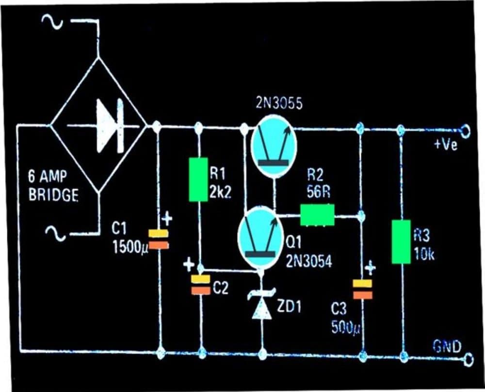
This simple efficient high current 2N3055 based power supply is designed to handle in excess of 3 amp of currents, but must not exceed 5 amps.
The voltage that is required to be stabilized can be adjusted through R1 and the value of the zener diode.
The diodes at the input are arranged in a bridge network configuration for rectifying the voltage applied from the transformer.
C1 smoothens the DC further to feeds the filtered DC to the control circuit made up of Q1 and Q2.
R1 is introduced to start up the circuit by providing the required biasing to the transistor pair.
C2 makes sure that the transistor receive a perfectly smooth DC at their base without any ripples.
The zener diode at the base of the Q1 clamps the transistor with a fixed biasing voltage and inhibits any rise at the output voltage, irrespective of the voltage at the input.
Meaning even if the input voltage from the bridge network rises, the output remains unaffected and produces the voltage defined by the setting of R1 and the zener diode.
Parts List
- Resistors are 1/4 watt 1% MFR
- 2.2 k, 10 k, 56 Ω = 1 each
- Capacitors
- Electrolytic 1500 µF / 50 V = 1
- Electrolytic 500 µF / 50 v = 2
- Semiconductors
- Bridge Rectifier Diodes 6A4 = 4
- Zener Diode 1 watt, voltage value as desired between 3 V to 30 V = 1
- Transistors 2N3055, 2N3054 = 1 each
- Large finned heatsink for the above transistors = 2
- Transformer 0-15V, 5 amp = 1


Questions & Answers
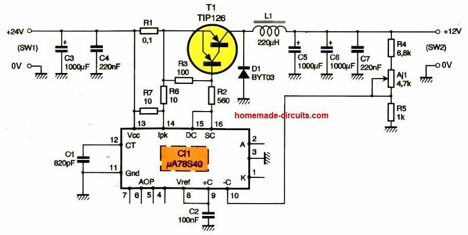
It would better to making a switching DC/DC converter – it has much better efficiency and not requires a heatsink .A couple of transistors (even one) may be used as amplifier error. As a PWM a Schmitt trigger with capacitor in feedback path may be used. A bipolar emitter follower (pnp and npn pairs) can amplify output current. A pulse transformer (with a ferrite core) and series capacitor may be used for drive the 2N3055 transistor – to matching impedances and save power.
Yes, switching converters are always highly efficient and better than linear regulators…thanks for your feedback…
Hello, good afternoon, I like the circuit, but I want to know what function R 2 = 56 ohm fulfills. Thank you very much
Hi, I think R2 is used to provide a stabilized feedback to the base of the pass transistor, to improve its conduction.
Could this circuit drive a 4 amps to a resistence of 0.8 ohms?
If the 0.8 ohms load consumes 4 amps only, then yes, this circuit will work.
Hello,
Here I am back at trying to understand the basics. I hooked up a Treadmill motor with the specs of 110VDC and 21A. 3HP to a simple bench power supply rated at 30V and 10A. As I turned the voltage knob on the power supply, even at hardly 2V, the motor began to spin, using hardly 1A.
My goal was to figure out the effect of and the relationship of voltage and amps. So I realized that Voltage seem to relate to the rotation of the armature and the Amperage relates to the load demand, which translates to torque. I assume horspower is along the same measurement as torque but I am not sure.
I also realized that the fan on the power supply would kick in more so in response to Amperage demand of the load than the turning it’s knob for more voltage.
So would I be correct to conclude that, looking at the specs of the motor. I assume that those specs means that the motor should not be connected to a power supply that is capable of supplying more than 110VDC along with more than 21A. And that you can supply it with more voltage so long as the supply will provide less amperage and vice versa that if the power supply provides more amps, it should provide less voltage. That is total combined of the two can not exceed the total of volts * amps, i.e. 110V*21A?
The rpm rating on the motor says 3200. Assuming the above conclusion of mine is correct, supplying more voltage correspond to more rotation on the motors armature, would this mean one can exceed the rpm rating of the motor beyond 3200? And that it is to be avoided or that the armature will not rotate any faster than that and will simply cause heat and other problems? Or that the motor might react the opposite and that with higher voltage its rpm will diminish aside from whatever else?
Furthermore, say for the above motor; if one had two choices for a power supply to it, one supplied higher voltage but less amps while the second provided less voltage but more amps, which one would be a safer choice?
I realize I brought up a quite few points, sorry about that.
Thank you in advance for any feedback.
Hi,
The voltage decides the speed and the current decides the load.
If voltage is less then speed will be less, or if current is less and voltage is good, again the speed will be less due to overload.
The speed will be good only if both voltage and current are good as per the load specs.
However, if the voltage is good and as per the loads specs then higher current will not harm the load, no matter how high the current is. But in this situation if the voltage incresaea even slightly then the load will burn.
On the other hand if the voltage is higher than the load specs, and the current is less, then again it will not harm the load since the voltage will keep dropping to the load specs.