Constant current generators (CCGs), as the name suggests, are circuits designed to produce a steady load current regardless of significant fluctuations in load resistance or voltage levels.
Basic Constant Current Generator Circuit
Illustrated in Figure 1 is a basic example of such a circuit.
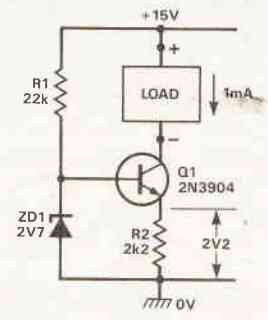
In this configuration, Q1 operates in the common emitter mode. A stable voltage of 2.7V is established at its base through R1-ZD1, resulting in an emitter current of approximately 1mA via R2.
Since the collector and emitter currents of a high-gain transistor are nearly identical, the collector current (which represents the load current) remains nearly constant at 1mA, even when the load resistance fluctuates from zero ohms to 12k ohms (a point at which the transistor approaches saturation).
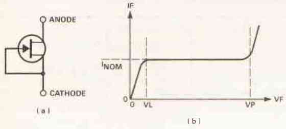
The standardized symbol for representing a constant current generator is shown in Figure 2a, denoting the collector-to-ground path of the configuration in Figure 1.
This symbol, however, does not provide insight into the specific circuitry of the constant current generator.
Two significant parameters characterize a practical constant current generator: its nominal operating current value and its dynamic impedance (Z).
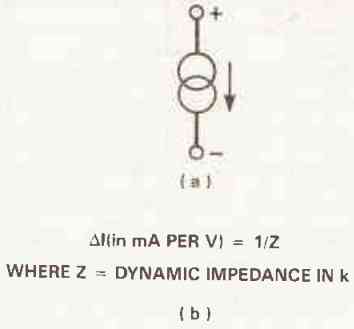
The dynamic impedance, Z, determines the accuracy of current regulation, as depicted by the formula in Figure 2b.
For instance, if the circuit shown in Figure 1 has a Z value of 1M, its current undergoes a variation of 1uA per volt alteration on the collector of Q1.
Constant current generators find applications both as dedicated current sources and as elements with high dynamic impedances.
These applications are illustrated in Figures 3 and 4.
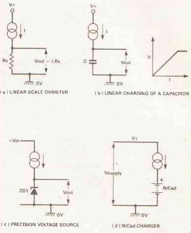
Figure 3a portrays the fundamental circuit of a linear-scale ohmmeter. Here, the Rx value is read on a simple voltmeter.
When the constant current generator's I value is set at 1mA, the output voltage corresponds to 1mV per ohm of Rx. Similarly, if ,I, is 10uA, the output becomes 10mV per k ohm, and so on.
In Figure 3b, the CCG facilitates linear charging of a capacitor, serving well in linear timebase generators and similar setups.
Figure 3c displays a common power supply application where the CCG imparts a consistent bias current to a zener diode, ensuring a highly stable output reference voltage irrespective of wide input voltage variations.
Figure 3d showcases the CCG's utilization as a Ni-Cad charger, delivering a uniform charge current regardless of the number of cells in the Ni-Cad stack.
In Figure 4a, the constant current generator functions as the emitter load for an emitter follower configuration.
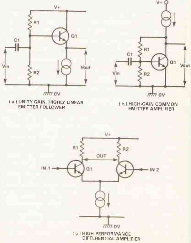
The generator's elevated dynamic impedance bestows exceptional linearity and nearly unity gain to the follower.
Similarly, in Figure 4b, the CCG takes on the role of the collector load for a common emitter amplifier.
The amplifier operates with significantly amplified voltage due to the CCG's high dynamic impedance (typically around 70dB).
Lastly, in Figure 4c, the CCG is positioned as the emitter load (tail) of a differential amplifier. Its substantial dynamic impedance empowers the amplifier with heightened gain, impeccable linearity, and an impressive Common Mode Rejection (CMR) ratio.
Constant Current Diodes
Practical constant current generators (CCGs) can be constructed using an assortment of discrete components or integrated circuits.
They can also be procured in a fully integrated format. Among the most straightforward CCG solutions is the so-called 'constant current diode.'
Illustrated in Figure 5, this device is essentially an n-channel depletion-mode JFET (junction field-effect transistor) in which its gate and source terminals are directly connected.
Consequently, when subjected to an appropriate voltage (typically adjustable within the range of 3V to 50V), it facilitates a steady current flow set to a predetermined value (typically manufactured with a tolerance of around +20%).
This class of devices is available within a specific range, showcasing typical l/Z ratios spanning from 0.5mA/3M Ohm to 5mA/0.3M Ohm.
Transistor-Based Constant Current Generator Circuits
Bipolar transistors can be adeptly arranged to function as effective constant current generators (CCGs), as already demonstrated in Figure 1.
This fundamental configuration can be readily modified in various manners to achieve distinct characteristics.
For instance, Figure 6 presents an 'inverted' version that furnishes a ground-referenced constant current output, adjustable from around 1 to 10mA via RV1.
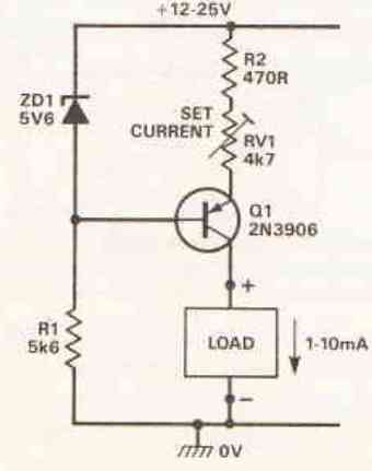
In many practical CCG applications, the precise value of the constant current isn't of paramount importance.
In such scenarios, the basic designs showcased in Figures 1 and 6 should suffice for most requirements.
If heightened precision is sought, enhancements to the reference voltage characteristics of these circuits are necessary to counteract the influence of supply line and temperature fluctuations.
One straightforward enhancement involves substituting R1 with a constant current generator, as depicted in Figure 7.
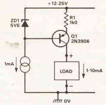
This alteration ensures the zener current (and consequently, the zener voltage) remains unaffected by shifts in the supply line voltage.
For instances necessitating superior precision, the zener reference should exhibit a temperature coefficient of -2mV/"C to align with the VBE coefficient of Q1.
A workaround involves utilizing a forward-biased red LED in lieu of the zener, as shown in Figure 8.
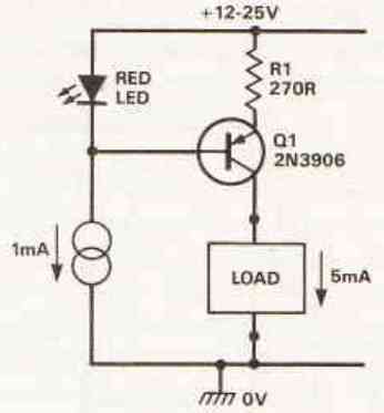
With the LED voltage approximately at 2V, only around 1.4V appears across the 270-ohm emitter resistor R1, thus establishing a constant current output level of approximately 5mA.
Notably, all the transistor-based CCG circuits thus far are '3-terminal' designs, requiring both supply and output connections.
Figure 9 introduces a 2-terminal constant current generator instance that generates a fixed 2mA and can accommodate supply voltages within the range of 15V to 40V. In this arrangement, ZD1 establishes a consistent 5.6V at the base of Q1.
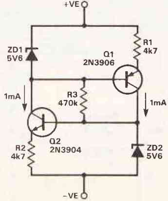
Consequently, via R1, it maintains a steady collector current of about 1mA. This current drives ZD2, which consequently maintains a highly stable 5.6V at the base of Q2.
Q2, in turn, maintains a constant collector current of about 1mA, driving ZD1.
Thus, the circuit operates as a closed-loop current regulator, generating a total constant current equivalent to the sum of the two collector currents. R3 functions as a startup resistor that delivers initial base current to the transistors.
Figure 10 presents a variable rendition of the aforementioned 2-terminal CCG. Its operational current can be adjusted within an approximate range of 1mA to 10mA via RV1.
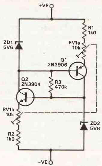
Noteworthy is that these two circuits require a minimum operating voltage of about 12V between their two terminals, with a maximum permissible voltage of 40V.
Op-amp-Based Constant Current Generator Circuits
High-performance constant current generators can be readily constructed using conventional op-amps, either on their own or in combination with an external transistor.
As demonstrated in Figure 11, a precision voltage-to-current converter can be fashioned by connecting a 3140 op-amp and a transistor in the configuration of a unity-gain voltage follower. The load current is obtained from Q1's collector.
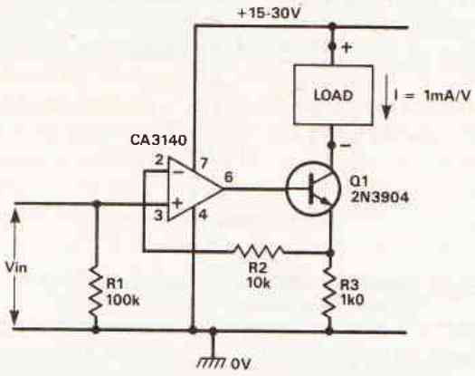
The voltage-to-current conversion factor, governed by R1, is 1mA/V at 1kΩ.
Figure 12 showcases how the aforementioned arrangement can be transformed into a precise 1-10mA constant current generator circuit.
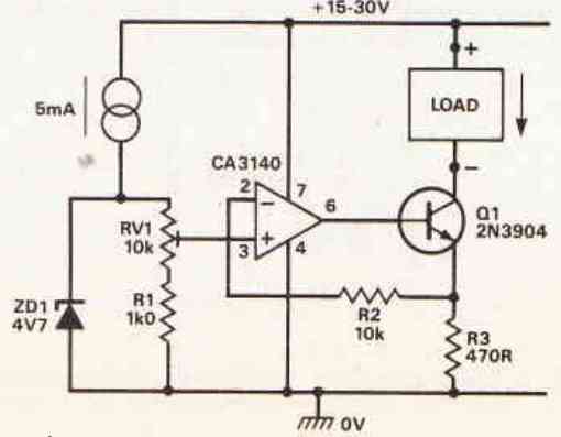
This modification involves supplying the current-setting input voltage through a stable 4.7V zener source and RV1. It's worth noting that the 4.7V zener exhibits an almost negligible temperature coefficient.
All the previously presented CCG circuits operate as unidirectional current generators, allowing the load current to flow solely in one direction.
A distinct type of constant current generator circuit is the voltage-controlled bilateral circuit, which serves to convert an AC input voltage into an AC load current that remains largely unaffected by the load resistance value.
An uncomplicated instance of such a circuit is depicted in Figure 13.
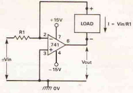
The op-amp functions as an inverter, utilizing the 'load' as its feedback resistor.
The circuit's inherent behavior leads to the feedback (load) current adjusting itself to match Vin/R1, regardless of load resistance, thereby achieving bilateral constant current generation automatically.
Notably, the output voltage directly correlates with the load impedance.
This bilateral circuit is particularly beneficial in scenarios where the load is entirely floating.
However, if the load is grounded on one end, the alternative circuit illustrated in Figure 14 can serve as a bilateral CCG.
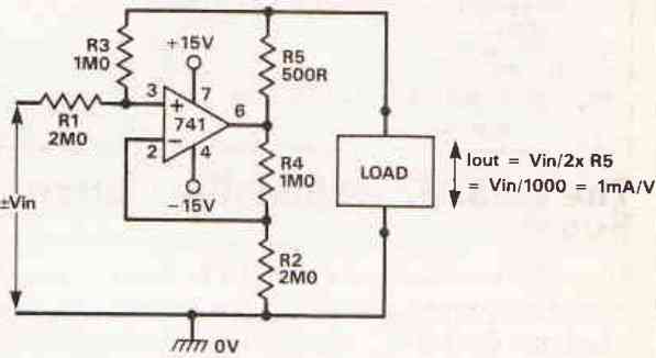
In this setup, with the indicated values for R1 to R4, the circuit's feedback mechanism ensures that the output load current is solely determined by R5 and Vin, regardless of load impedance.
At the provided R5 value, the load current equates to 1mA/V. Significantly, the circuit's output voltage is directly proportional to the load impedance, rendering it suitable for adaptation as a testing instrument for measuring impedance.
An Innovative High-Current Generation Concept
The majority of common current control generator (CCG) circuits are primarily engineered to provide relatively modest output currents, typically ranging within a few milliamperes.
However, certain situations arise, such as the need to charge nickel-cadmium batteries (NiCads), that necessitate substantial output currents.
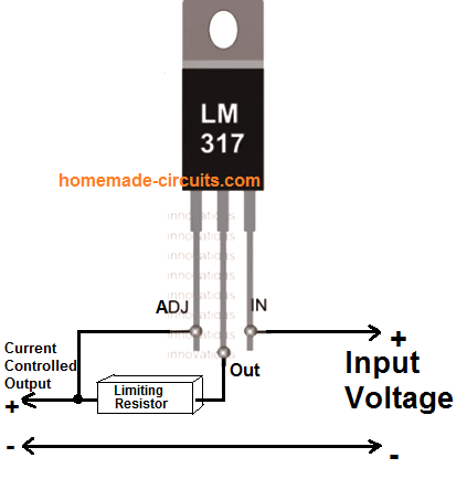
A straightforward approach to achieving this requirement involves the utilization of an LM317, a three-terminal voltage regulator integrated circuit (IC), configured as illustrated in Figure 15.
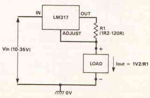
The fundamental operation of this IC results in its OUT terminal automatically adjusting to a level 1.2 volts higher than the setting on the ADJUST pin.
In the diagram, the output current of the IC flows through a 'sensor' resistor denoted as R1, where the lower end of R1 is connected to the ADJUST pin.
Consequently, the output current effortlessly self-regulates itself to a magnitude equivalent to 1.2V divided by R1.
This behavior remains nearly independent of the load impedance, effectively rendering the circuit a consistent current generator.
When R1 assumes a value of 1Ω, the circuit performs as a 1-ampere generator, whereas at a value of 120Ω, it functions as a 10-milliampere generator.
The circuit is compatible with input voltages (power supply) within the range of 19 to 35 volts.
The Remarkable LM334Z Adjustable Current Source
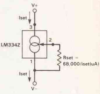
The LM334Z IC is an impressive two-terminal constant-current source that demonstrates outstanding performance.
It operates effectively with supply voltages spanning from 1 to 30 volts and provides the flexibility to set its operating current to any value between 1 ampere and 10 milliamperes by using a single external resistor (Rset).
Figure 16 presents the fundamental characteristics of this component, which is encapsulated within a three-pin package.
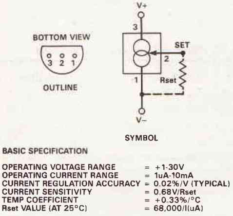
It's worth noting that the symbol of the LM334Z in Figure 16 might provide an oversimplified representation of its functionality.
For a more accurate depiction of its operation, refer to Figure 17, which outlines the following key points.
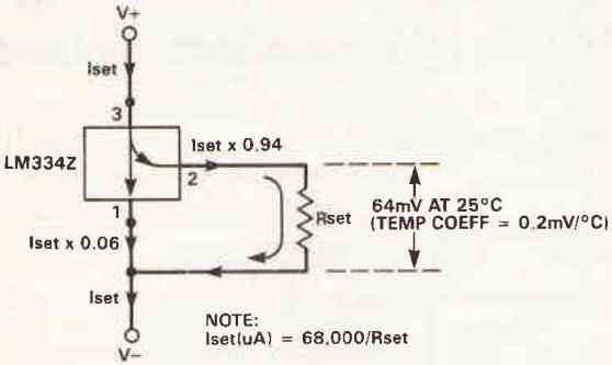
The current denoted as Iset, entering the LM334Z through pin 3, bifurcates within the device.
Merely 6% of this current flows to the negative terminal via pin 1, while the remaining 94% traverses the path via pin 2 and Rset, reaching the negative terminal as well.
At a temperature of 25°C, a voltage of 64 millivolts appears across Rset (between pins 2 and 1). This voltage demonstrates a temperature coefficient, represented as t, equivalent to +0.2 millivolts per degree Celsius.
As a result, Iset is influenced by temperature, and at 25°C, its value in microamperes corresponds to 68,000 divided by the resistance value of Rset.
Effective Utilization of LM334Z as a Two-Terminal Current Source Figure 18 illustrates the fundamental application of the LM334Z as a two-terminal current source.
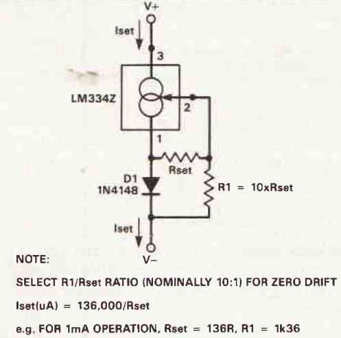
Additionally, Figure 19 presents a modification to the circuit incorporating R1 and D1. These components, sharing the thermal environment of the LM334Z, serve to eliminate the temperature sensitivity of the current source.
Temperature-Sensitive Operation and Precision Adjustment
The operating current of the LM334Z inherently exhibits sensitivity to temperature variations, governed by the formula: Iset = (227 microvolts times the temperature in Kelvin) divided by Rset.
Although not its primary design purpose, the LM334Z can be judiciously employed as a relatively accurate temperature-to-voltage converter.
A version of such a circuit is depicted in Figure 20, featuring an output sensitivity of 10 millivolts per Kelvin.
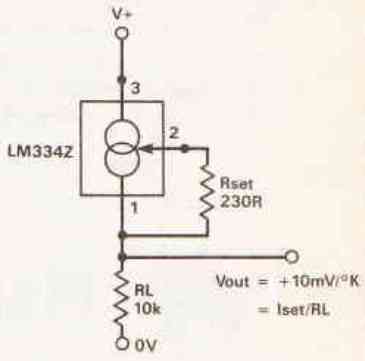
In this configuration, the choice of Rset is made to yield an Iset current of ideally 293 microamperes at 20°C (approximately 2.93 Kelvin), thus resulting in an output voltage of 2.93 volts.
Practical considerations reveal that the initial error of the basic circuit, employing 1% resistors, could reach as high as 5% (approximately 150 millivolts), translating to an error of 15 degrees Celsius.
If such precision is of paramount importance, this error can be rectified by fine-tuning the value of Rset to achieve an output of precisely 2.93 volts at 20 degrees Celsius.
The Concept of the Current Mirror
Before concluding this exploration of circuits generating constant currents, it's important to acknowledge a pivotal component in modern linear integrated circuit (IC) design known as the 'current mirror.'
This design takes on the fundamental structure depicted in Figure 21.
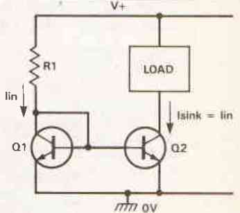
In this arrangement, Q1 and Q2 represent a pair of precisely matched transistors, often integrated, and share a common thermal environment.
When an input current (Iin) is directed into diode-connected Q1, it triggers Q1 to produce a proportionate forward base-emitter junction effect on Q2.
Given the close matching of these transistors, this action prompts Q2 to sink an almost identical ('mirrored') quantity of collector current (Isink).
Consequently, Q2 functions as a stable current source that can be regulated via Iin. Remarkably, this current source maintains its consistency even when subjected to collector voltages as low as a few hundred millivolts.
In practical applications, the Isink current typically registers 1% to 2% lower than Iin, particularly when utilizing ideally matched transistors, as a portion of I is utilized as base-drive current.
It's important to note that the circuit remains functional as a current-controlled constant current generator, even if the characteristics of Q1 and Q2 are not ideally matched.
However, in such cases, it might not function as a precise current mirror, as Isink and Iin could exhibit notable discrepancies.


Questions & Answers
Hello
I am a student and have been assigned to find a constant current circuit that can deliver up to 40A, which is ALOT i know. My supervisor told me to look at the circuits in this page, however the can only deliver quite small currents. I was wondering if I can use the same concepts/circuits with power components (transistors,resistors, etc.) and achieve the quite high current I need to.
What do you think?
Best regards a 2. semester student way above his abilities
Hi, yes you can definitely do that.
Please refer to the following article, which shows a few MOSFET based designs at the bottom of the post….you can upgrade the MOSFET accordingly and fulfil your project requirements:
https://www.homemade-circuits.com/universal-high-watt-led-current-limiter/
Hello good afternoon my name is Carlos from Argentina. I have a curiosity about what it is used for and how to use a generator of 4 to 20ma, the question is if you could make a detailed report on how it is used and how it works …. Thank you very much.
Hello Carlos,
You can get all the required information under the following post:
https://www.homemade-circuits.com/constant-current-source/
The current max output can be simply adjusted by adjusting the value of the current sensing resistor, as explained here:
https://www.homemade-circuits.com/simple-current-sensor-circuit-modules/
hi, swagatam,
I am trying to get the basic lm317t circuit to give 100ma (9v psu supply). i am using an 18 ohm resistor and 50 ohm pot connected in parallel to try to adjust the current to 100ma, betwen the adjust and output pins. but it is not working. i am getting frustrated !
i have a 1uf cap between the +ve and -ve supply and 1uf cap between adjust and -ve supply.
the pot just does not regulate at all ??? test probes are between -ve and output pins.
i must be making a basic mistake but where / there are only a few components.
dave
Hi Dave,
Have you configured the LM317 in the following manner:
Please do not use the pot at first, try with a fixed resistor instead. Let’s say if you use the 18 ohm resistor alone, then as per the formula:
R = 1.25/current
Output max Current = 1.25/18 = 0.069 amperes = 69 mA
Please confirm the above and let me know.
hi, yes i configured it like that.
with just the 18 ohm res the current reads 0.204A (204MA)?????.
I have also tried several lm317t s with the same result, none of them seem to regulate.
dave
What happens if you change the resistor value, does the max current output also changes?
I hope you are checking the output current by directly connecting the ammeter probes across the output +/- supply lines.
If the max output current changes that would mean the IC is regulating the current.
hi,
yes, the output current is measured across the -ve and the output pin(2).
and does not change from 0.2 amp when changing the resistor.
i think i must have some dodgy LM317t s.
i have ordered some more so will wait till i get them, and get back to you.
dave
hi swagatam,
yes, i did connect it that way, (not directly to pin 2)but at the junction of the res and pin2. and got 0.2A . Ithink i have dodgy Lm317s, I have got some more on order and will get back to you when i have tried them,
dave
hi again swagatam,
this is driving me up the wall.
i got the new lm317t’s.
connected as you showed, (PIN1) adjust to pin 2 (out) with 18 ohm resistor.
pin 3(in) +9v supply psu
+ve meter probe to junction of resistor and pin 2
-ve meter probe to -ve 9v supply
STILL 0.2A ?????
changed resistor to 120 ohm , still 0.2A
resistor measurements on lm317 :-
pin 1 (adj) to pin2 (out) 7.53Mohm
pin1 (adj) to pin3 (in) 22.72Mohm
pin 2 (out) to pin1 (adj) 8.01Mohm
pin2 (out) to pin3 (in) 4.30Mohm
the circuit cannot be any simpler , i am now doubting my meter current readings, i am totally lost.
dave
Hi Dave,
Even without the IC, the resistor itself should be able to limit the current and cause different current levels at the output, so it seems the meter is not good.
Why not test the setup with a real load.
Do you have a small flashlight bulb or maybe a small DC motor, which you can use to check the response?
hey, swagatam,
using a load of 100ohms the circuit seems to regulate 🙂 and i can get 100ma, through the resistor.
it seems it just needed a load for current regulation.
thank you for your suggestions.
(i will use it for a milli ohmmeter and compare to it my Rhopoint milliohmeter.)
dave
That’s a good point Dave, yes, it will require a output load for initiating the current control, glad it is solved now.
hi,
ok, will try using a small load, say a 100ohm resistor and check the current.
dave
Thanks Dave,
Ok, in that case it seems the LM317 ICs could be dodgy, and you can confirm by replacing them with the genuine ones.
Hi, The output is not measured from pin#2 of the IC, the output is measured across the junction of the resistor and the ADJ pin of the IC, and the ground line.
So the positive probe of the ammeter goes directly to the junction of the resistor and the ADJ pin, and the negative probe of the meter connects directly with the ground line.
Hi Mr. Swagatam;
I have a 12V spot welding circuit and I may use the batteries with various current capacity. How can I limit the current or gain about 20A or lower fix current for instant in case I use 60A battery.
Hi Suat, you can try the MOSFET current limiter circuit, as explained in the following article:
https://www.homemade-circuits.com/universal-high-watt-led-current-limiter/