This LED light bar with dimmable feature will allow the user to adjust the brightness of the lamp in 4 steps, with100%, 50%, 10% and 0% illumination control at each subsequent steps.

The idea was requested by one of the avid readers of this blog. Here's the required working concept.
Hi Swag !
I stumbled across your web page whilst searching for a solution to make an effective touch led lamp.
Actually the one my dad uses at night has gone kaput. So I thought why not make him one - being an engineer in the past.
NTE’s touch dimmable led light bar. I love how it’s built and I’d like to use this as a ref to make a night lamp for my dad whose old and needs it at night….
I intend to may be use a dimmable Led bulb or a led strip to make the lamp.
If you can help me with the circuit and maybe a tutorial sort as I’ve been out of this for a long time, it would really mean a lot.
Monish
The Design
The basic design of the proposed touch dimmable LED light bar circuit can be seen in the block diagram below:
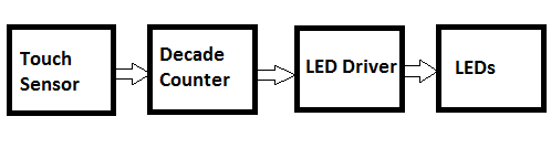
The touch sensor converts the tiny finger touch signal into amplified electrical pulses. The next decade counter stage converts these pulses into shifting logic levels across its outputs.
These shifting logic pulses are fed to the corresponding LED drivers which convert these signals into a sequentially varying voltages for the LED stage.
The varying voltages from the transistor stage which are set at specified levels cause the LEDs to illuminate with different light levels or brightness., accomplishing the dimmable effect on the LEDs.
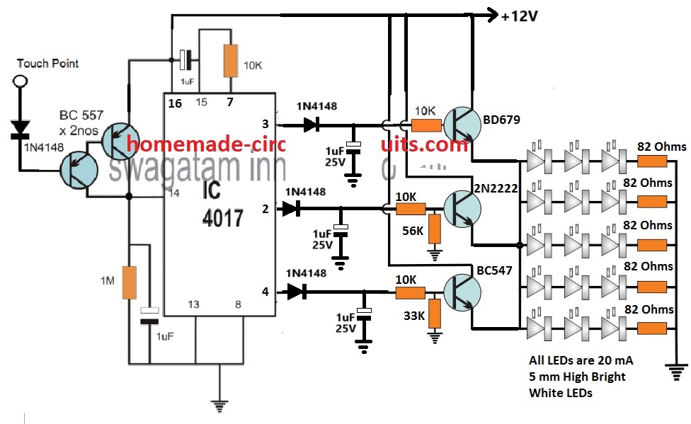
How the Circuit Works
Referring to the circuit diagram above, the basic circuit functioning could be understood with the help of the following points:
The two BC557 transistors at the left side of the diagram form the touch sensor stage.
Tiny electrical pulses from the finger are amplified to the supply level and applied to the clock input of the IC 4017.
The IC 4017 is a 10 stage divide by 10 Johnson decade counter, which responds to these input signals and converts them into a shifting HIGH logic across its output pins from 3 to 4.
Initially when the circuit is powered, the 1uF at pin15 of the IC resets the IC so that the HIGH logic is set at its first pin out #3.
Due to this the corresponding BD670 transistor stage conducts and illuminates the LED array brightly. The BD670 being a Darlington device illuminates the LEDs with high brightness.
At this stage the brightness of the LEDs is maximum also because the BD670 has no potential divider at its base configuration.
This allows it to deliver an optimum 11 V from the 12 V supply to the LEDs at full current, illuminating the array with full brightness.
When the touch sensor is touched, the decade counter responds and causes its output logic to shift from pin#3 to pin#2.
This shuts off the BD670 stage and powers the pin2 transistor stage which is also wired like an emitter follower.
Therefore, now the 2N2222 transistor becomes responsible for illuminating the LED array.
However, since the base of the 2N2222 emitter follower is rigged with a potential divider that creates around 10 V at its base, causes the emitter of the 2N2222 to have a decreased emitter voltage, at around 10 V.
The 1 V reduction of the supply to the LEDs, decreases the illumination and dims the LED brightness to 50% less than the original level.
Next, when the touch sensor is touched again, shifts the HIGH logic from pin#2 to pin#4 of the IC. Likewise, now the BC547 driver stage activates and takes over the job of illuminating the LEDs.
But again, due to a potential divider at its base set to generate approximately 9 V output at the emitter, causes the LEDs to further dim at the lowest 10% of its original full level.
After this when the touch pad is touched, the clock signal at pin#14 of the IC shifts the HIGH logic from pin#4 to the next subsequent pin which is the pin#7.
However, since the pin#7 is attached with the reset pin#15, cause the IC output reset back to pin#3. This enables the LEDs to illuminate again with full brightness.
Thus means the dimmable tube light bar does not have a switch OFF step across the touch sensitive range.
If you wish to have the switch OFF function at the last stage, after the pin#4 step, you can achieve this simply by replacing the pin#7 with pin#10.
Meaning, pin#15 now connects with pin#10 via the 10K resistor. This will allow the 3rd touch action to switch OFF the entire LED bar, and the next subsequent touch will yet again restore the LEDs to its full brightness level.
Using Current Control for Dimming
In the above concept, the LED driver section dependent on a voltage controlled dimming on the LEDs.
In this concept the transistors are configured as emitter followers and their base voltages are controlled using potential dividers.
This allows their emitters to follow the base voltage and produce an equivalent controlled voltage for the LEDs.
This controlled voltage is appropriately calculated to generate the sequential dimming effect on the LEDs.
However, calculating and adjusting the base potential divider networks can be time consuming.
Therefore to make things easier we can simply convert the above voltage controlled dimming effect into a current controlled dimming effect, as depicted in the following diagram.
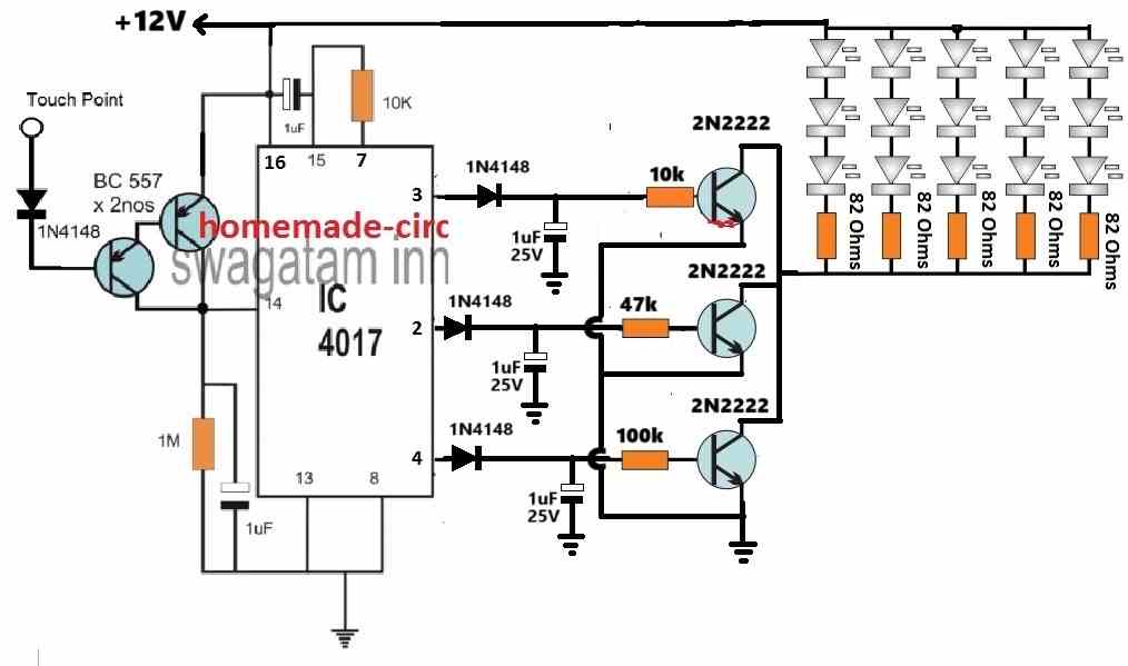
In the above configuration, the LEDs are shifted on the collector side of the transistors, and the base resistors are replaced with single resistors.
Here, the base resistors govern the collector current to the LEDs, which can be appropriately calculated for generating the desired sequential brightness control on the LEDs.
The following formula can be used for manipulating the base current for each of the transistors to illuminate the LEDs with a varied sequential brightness.
R = (Supply Voltage - Base/Emitter drop) x hFE / LED Current
Practical Example
In the above formula, the "R" represents the base resistors of the transistors.
Let the supply voltage be = 12V.
The base/emitter drop for a BJT is normally around 0.7V
The hFE of 2N2222 can be taken as 100.
Let's consider each LED to be rated at 20 ma, so each LED string with 3 series LEDs will also consume 20 ma. Since 5 LED strings are used, the LED current for generating maximum brightness on the LEDs will be 20 mA x 5 = 100 mA.
Therefore substituting the above values in our formula we get:
R = (Supply Voltage - Base/Emitter drop) x hFE / LED Current
= (12 - 0.7) x 100 / 0.1 = 11300 ohms
Thus a 11.3k resistor will cause all the LEDs to illuminate with maximum brightness.
Now, suppose we want the LEDs to illuminate with 50% less brightness on the second step. For this we have to reduce the LED current to 100/2 = 50 ma.
R = (Supply Voltage - Base/Emitter drop) x hFE / LED Current
= (12 - 0.7) x 100 / 0.05
= 22600
Therefore to illuminate the LEDs with 50% less brightness we have to select the base resistor of the second transistor as 22.6k
And so on, in this way we can generate the desired sequentially varying brightness on the LEDs, simply by changing the base resistor values of the transistors.




Questions & Answers
Really nice article and very informative, thank you for the time and effort for explaining everything!
Hi, I think this circuit is close to what I am looking for.
I need to cycle between three states as the touch point is activated – Off – Red, Warm White, Bright White – Off. Using three separate Single Color LED strips
Do you have any suggestions for this modification, or an alternative using a single RGB strip?
Hi, you can use the same circuit, with a few modifications:
remove the 56k, 33k resistors.
remove the LEDs from the emitter side, and connect the strings in series with the collectors of the transistors.
Connect the emitters with the ground line directly.
Hi, I am looking for a touch sensor that will work underwater. (to add in front of a dimming circuit such as this one.) So far, the most promising seems to be am infrared touch sensor, though a small window. when you cover the small window with a finger, it pulses the dimming circuit above. do you have any advice on particular infrared emitters or detectors to use? or a filtering circuit to eliminate stray reflected light from the lens or small particles in the water? or is there a better touch sensor method you can think of?
Thanks, & compliments on a great website!
Hi, you can try the following arrangement, hopefully this should fulfill your requirement:
Thanks for the quick response on a Sunday! And thanks for the circuit suggestion.
So do you think an infrared sensor is the best way to go here, or is there another technology better suited?
For the filtering of the IR sensor, I had thought to use a basic lm358 circuit, using a potentiometer to set the comparison voltage high enough such that anything below 40% or 50% relative collector current gets filtered out. And feeding the output of the lm358 directly into the pin 14 of the 4017. Is the circuit with the double 557 transistors more stable? Would I replace the 10k resistor with a potentiometer to change the sensitivity?
With the LM358, I had also thought to add a capacitor in parallel with the sensor resistor, so that the greater than 50% collector current needs to flow for at least half a second before it would switch the count up. (in order to filter out something else floating by briefly, or a brief brush against the arm or leg.) where would I place the capacitor with the double 557 circuit?
You are welcome!
Since it is an underwater application, infrared will suit better.
Sensitivity of the circuit suggested cannot be changed, since it is configured as a digital output
If you want to control the sensitivity of your optocoupler output then your op amp idea will be more appropriate.
More information regarding optocoupler interfacing can be learned from the following article:
Optocouplers – Working, Characteristics, Interfacing, Application Circuits
The capacitor could be placed at the input LED side. Two resistors could be connected in series with the LED positive line, and a suitably rated capacitor connected between the junction the resistors, and the negative line or the LED cathode line.
Hi, one further question: in my case, I put the lowest power LED level on pin3. Now I want to use a comparator so that in a particular situation, the comparator (an lm358, since I am using those already) would reset the counter & keep it in reset mode. Effectively, from then on, resetting any other power modes, and only allowing the low power light mode.
Can I run the output from the lm358 directly to the pin 15? Or would this cause problems with the reset function of pin 7? I can imagine since the output of the lm358 is either active on, or active grounded, the active grounded condition would keep the pin 7 from resetting the counter. Would a simple diode on the output of the lm358 be sufficient to prevent the grounding?
Hi, yes that will work.
You can use a diode at the op amp output and connect its cathode to pin#15 of IC 4017, for the intended results!
Hi can we use IR remote sensor instead of touch sensor
for IR remote you will have to modify the IC 4017 in the following manner:
https://www.homemade-circuits.com/how-to-make-simple-infra-red-remote/
Hi, one more question.
I have added a p-mosfet before the circuit, between the v= of the battery, and the Vcc main power line of the circuit. So that the battery stays disconnected and doesn’t drain until I am ready to use it.
The gate is connected to the source of the mosfet with a 470k resistor. I would expect the Vgs to be 0v until I pull it down with an extra transistor and an ‘on’ signal. However, without doing anything, the Vgs seems to settle at -0.3v
https://ibb.co/0ts16qs
here is the circuit. any idea what is causing the leakage? or is it a high frequency on/off oscillation? And how do I fix it?
much appreciated!
Hi, the image shows an N channel MOSFET?
But the N channel looks correct, so the diagram has no problems….I think you can try changing the MOSFET or try a BJT instead.
the n channel mosfet is the one that pulls down the gate of the p-channel mosfet (i incorrectly wrote that a transistor pulls down the gate)
so the top chip, with 8 pins, is the p-channel mosfet (dmp2022)that is giving me the problems…
Hi, never mind – I finally fixed it. The really confusing part was that I was still getting the Vgs voltage drop even when everything else was removed. i.e. leaving just the input voltage Vbatt, the resistor across G-S, and the p mosfet…
I don’t know if I fully understand why, but I think when the resistor across G-S gets very large, the own internal capacitance of the mosfet can cause a small current pulse into the resistor and cause a voltage that turns on the mosfet. I assume with 470k it was oscillating to a steady state Vgs of -.3, and with 100k to a Vgs of -0.05v. with 24k I couldn’t measure a Vgs, but the output still had .02 and was passing an initial peak that latched Vcc With 1k everything works perfect! I will try 5 or 10k tomorrow, just to reduce power loss a bit when on. But otherwise, I will live with the 1k.
Yes that was the exact problem, glad it is solved now…
you can replace 470k with 10k and check the results.
for the N channel also, you can replace the 470k with 10k, and R98 with 100 ohms
Sir ,thanks a lot for this circuit , I made it and it worked well with 12v battery but when I use 12 v adapter it loses touch l.e touch does not work at all.Kindly guide me.
Bharat, try this: Connect a diode at each of the outputs of the 4017 IC such that their anode is connected to the IC output pin and the cathode is connected to the transistor base resistor.
After this, connect a 1uF between the cathode and ground of each diode.
Also try replacing the 1uF at pin14 with a 10uF.
Additionally make sure that your adapter has a high value filter capacitor in the order of 2200uF
Very smart and updating electronic devices and circuits. Thanks alot
What’s the max amount of LEDs per row?
As shown in the diagram.
15? What if need more than 15? Changing the serial resisters to LEDs is enough?
Thanks!
You can add more LEDs in parallel with individual series resistor. But if the there are too many of them then the transistor and their base resistor will also need to be modified.
Hi Swagatam,
I am working on a circuit that uses two 4017 which work together. The first one is driven by a 555 and rotates through the sequence and then the second 4017 gets its clock from pin 12 of the first 4017. The second 4017 drives npn transistors tocfd grounds columns of LEDs that are driven by the first 4017. The problem is the 4017 can’t drive several LEDs due to current overload. Therefor I want to drive npn transistors with the first 4017 to power a string of LEDs similar to your circuit above. With my lack of knowledge, I have never quite Understood how to power circuits with npn transistors. I know I can use a transistor pair( npn grounding pnp to supply a circuit but that uses more components and takes up extra space on the PCB. If you could please comment and elaborate to enlighten me with the proper way to drive a LED circuit with npn transistors on the high side, I would much appreciate it
Hi Norman,
For an NPN transistor, its base receives the switching signal through a resistor. The LEDs are supposed to be connected across the positive supply and the collector through a calculated resistor. The emitter is supposed to be connected directly to the ground supply. This is the basic set up that you need you implement for an NPN transistor.
You can check out the following examples:
https://www.homemade-circuits.com/rotating-led-chakra-circuit-for-god-idols/
https://www.homemade-circuits.com/single-push-10-step-selector-switch/
hi swag..I need a circuit touch dimmable circuit just like this above.but can Run. on 5v DC supply.I want to power a 1 watt 5v led lamp with it.thanks
Hi Joseph, you can use the same circuit which is shown above with a 5V supply and 5V LED lamps, it will still work.
So there won’t be modification and will it still be dimmable??
Also can i use a piezo sensor as the touch pad?
Yes it will still dimmable.
Piezo sensor will not work, since the touch needs to be direct finger touch
How Can i modify it to work with piezo??
Thanks
You can connect the piezo between base and ground, and a 1K resistor across base and positive of the BC557 transistor.
Hello boss ,over here..i couldn’t get bd679 or any equivalent transistor..
Can u suggest any other transistor i can use in place of it??
Hello Joseph,
The transistor numbers are not critical at all, you can try any other equivalents. You can try BD139 or TIP122 instead of the BD679….
alright boss thanks for your help I really appreciate.if I encounter any difficulty or issues,I’ll reach out to you.
No problem Joseph, you are always most welcome.
Hello boss i made the circuit.but i used a 13003 transistor in place of bd679.
When powered..the out put was low that is.the led wasn’t bright..what could be the problem and please suggest a solution
Hello Joseph, 13003 is not recommended, use 2N2222 instead you will get higher brightness.
Also boss “swag” I can I use the input stageof this circuit given..as the input of led dimmer circuit using same CD4017 ic but having a transistor at the output??without issues.thanks hoping to get a reply from you much love????
Yes you can use the circuit as it is shown in the diagram.
Good day! Just wanna ask if this circuit is battery powered or outlet powered? If outlet powered, what additional component can be used in order to convert AC voltage to DC Voltage
Hi, it can be both, battery powered or outlet powered.
For outlet power, you can use any ordinary 12V, 1 amp smps adapter.
If incase i want it to be usb powered like usb to laptop or usb to a charger head cause usually usb connector has a maximum voltage of 5V, is it possible to step down the voltage of the circuit without affecting its real functionality as a 12V circuit?
The circuit can work with 5 v also, however with a 5 v only one LED can be used on each LED string. To increase the brightness you can use 1 watt LEDs, meaning total 3nos of 1 watt LEDs across the 3 transistor emitters.
Also you will need to replace the 82 ohms resistors with 10 ohm 1 watt resistors.
For the transistors you will need to use TIP122 transistors.
Alright thanks a lot! Appreciate it have a good day!
Hello again Sir! Just wanna ask how does this circuit convert ac voltage from the outlet into dc since LED is applicable for DC voltages? And for the touch sensor, is the sensor only a piece of copper wiring connected to the diode and transistor? is it possible to install a touch pad sensor on it? if so, what touch pad controllers are applicable? thank you!
Hello Ryuchi, the above circuit will not convert AC to DC from the outlet, rather you will have to use an AC to DC 12v adapter to provide the required 12V DC power to the circuit…Any metal piece can work as the touch sensor…even a small piece of open wire will also do.
Good day! I would like to ask what is the current of the whole circuit? And for the current passing through each component, how are those being calculated? Just needed in research thanks!
Hi, the current is mainly consumed by the LEDs, the current consumed by the 4017 IC is negligible. The base resistors of the transistors and the LED series resistors determine how much current the LEDs can consume.