• Skip to primary navigation
  • Skip to main content
  • Skip to primary sidebar

Homemade Circuit Projects

Get free circuit help 24/7

  • 1000+ Circuits
  • Privacy Policy
  • About Us
  • Contact
  • Disclaimer
  • Videos – Circuit Test Results
You are here: Home / Home Electrical Circuits / Solving LDR Controlled LED Emergency Lamp Problem

Solving LDR Controlled LED Emergency Lamp Problem

Last Updated on June 15, 2019 by Swagatam 2 Comments

The following post discusses the troubleshooting of an automatic LDR controlled emergency lamp circuit which was requested to me via email by one of the keen followers of this blog. Let's learn about the issue and its solution.

Technical Specifications

Dear Sir,

I am following you on your website and I thank you for your valuable contributions as I am a electronic enthusiastic from my childhood.

I love to build projects a for my own use.

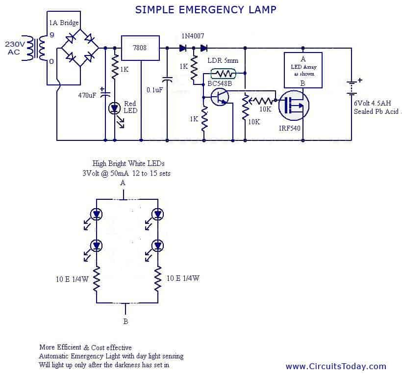
I seek your help in building a simple but efficient automatic (overcharge cut off) led base emergency light with LDR sensing. Need to use 12 or more led to light up. Can you send me a simple and efficient circuit with spare details.

Please help me so that I can build this asap. Attached one circuit for your reference I tried to build this but failed.

The led is not stopping when light hits also not stopping when mains on. When light hits led’s just dimming not turning off. If you can please help me. Check if there are any errors on this circuit. Please.

Best Regards

Hariesh

Analyzing the Circuit

Dear Hariesh,

Make the base/ground resistor of the BC548 transistor to 47K and see what happens. If it still doesn't work, replace the mosfet with a 8050 transistor.

A mosfet is absolutely not required for such a simple application.
The given mosfet is an N-channel but the diagram incorrectly shows it as a P-channel.

Regards.

Dear Sir,
Sorry to bother you again.!!!

Thank you for your prompt response . can you illustrate the pin connection of 8050 in place of mosfet.?
Best RegardsHariesh

If you hold the transistor with the printed side toward you with its pins down, the center pin will be the base, the right side pin will be collector and the left side will be the emitter.

The pin toward number 8 will be the emitter, the pin at "0" will be collector...
Base will go to the 10K resistor, collector toLEDs and the emitter to ground.

Dear Sir,You are great..!! finally half success now LED turns off in the presence of light. but not when i plug in mains power. any thoughts on this.? please.

Check the 1K resistor which is connected from base of BC548 to positive between the diodes. If it's connected properly the circuit will surely switch off in the presence of AC mains.

Dear Sir,

Thank you so much for your help. the following changes have led to success as advised by you and it works like a charm.

Replaced MOSFET with 8050.

1k Resistor was not connected properly due to oversight.

Could you kind enough to explain why MOSFET was not working even though I have connected properly. Just out of curiosity and to learn. 🙂

Once again I thank you for your great help.
Regards

Hariesh

Problem Solved

The mosfet should have also worked, there can be many reasons why it didn't work, may be due to some leakage voltage across gate and positive, due to wrong pin connections or simply because the device may be faulty.
Regards.


Previous: How to Control Motor with a Cell Phone
Next: LED Tail Ring Light Circuit for your Car

About Swagatam

I am an electronic engineer (dipIETE ), hobbyist, inventor, schematic/PCB designer, manufacturer. I am also the founder of the website: https://www.homemade-circuits.com/, where I love sharing my innovative circuit ideas and tutorials.
If you have any circuit related query, you may interact through comments, I'll be most happy to help!

You'll also like:

  • 1.  Remote Controlled Submersible Pump Circuit
  • 2.  10 Automatic Emergency Light Circuits
  • 3.  Emergency Generator Circuit Power Distribution
  • 4.  Making a “Helping Third Hand” for Aiding Soldering Jobs
  • 5.  Simple Refrigerator Protector Circuit
  • 6.  Cell Phone Emergency Charger Pack using Ni-Cd Batteries

Please Subscribe (Only if you are Genuinely Interested in our Newsletters)


Reader Interactions

Comments

    Your Comments are too Valuable! But please see that they are related to the above article, and are not off-topic! Cancel reply

    Your email address will not be published. Required fields are marked *

  1. Search Related Posts for Commenting

  2. Abdul Matheen says

    hi sir iam not a professional in electronics and iam unable understand the circuit diagram, so i want to make a simple led emergency light please guide me

    Reply
    • Swagatam says

      hi abdul, you can try the first circuit from the following link:

      https://homemade-circuits.com/2011/12/how-to-make-efficient-led-emergency.html

      Reply


  3. COMMENT BOX IS MOVED AT THE TOP


Primary Sidebar

Electronic Projects Categories

  • 3-Phase Power (15)
  • 324 IC Circuits (19)
  • 4017 IC Circuits (51)
  • 4060 IC Circuits (25)
  • 555 IC Circuits (92)
  • 741 IC Circuits (18)
  • Amplifiers (49)
  • Arduino Engineering Projects (82)
  • Audio Projects (84)
  • Battery Chargers (75)
  • Car and Motorcycle (87)
  • Datasheets (45)
  • Decorative Lighting (Diwali, Christmas) (31)
  • DIY LED Projects (81)
  • Electronic Components (97)
  • Electronic Devices and Circuit Theory (35)
  • Electronics Tutorial (99)
  • Fish Aquarium (5)
  • Free Energy (34)
  • Games (2)
  • GSM Projects (9)
  • Health Related (17)
  • Heater Controllers (23)
  • Home Electrical Circuits (98)
  • Incubator Related (6)
  • Industrial Electronics (26)
  • Infrared (IR) (39)
  • Inverter Circuits (94)
  • Laser Projects (10)
  • LM317/LM338 (21)
  • LM3915 IC (24)
  • Meters and Testers (54)
  • Mini Projects (153)
  • Motor Controller (64)
  • MPPT (7)
  • Oscillator Circuits (12)
  • PIR (Passive Infrared) (8)
  • Power Electronics (33)
  • Power Supply Circuits (66)
  • Radio Circuits (9)
  • Remote Control (46)
  • Security and Alarm (56)
  • Sensors and Detectors (115)
  • SG3525 IC (5)
  • Simple Circuits (72)
  • SMPS (30)
  • Solar Controllers (60)
  • Timer and Delay Relay (51)
  • TL494 IC (5)
  • Transformerless Power Supply (8)
  • Transmitter Circuits (38)
  • Ultrasonic Projects (12)
  • Water Level Controller (45)

Follow Homemade Circuits

Facebook
Twitter
YouTube
Instagram
My Facebook-Page
Quora

Feeds

Post RSS
Comment RSS

Circuit Calculators

  • AWG to Millimeter Converter
  • Battery Back up Time Calculator
  • Capacitance Reactance Calculator
  • IC 555 Astable Calculator
  • IC 555 Monostable Calculator
  • Inductance Calculator
  • LC Resonance Calculator
  • LM317, LM338, LM396 Calculator
  • Ohm’s Law Calculator
  • Phase Angle Phase Shift Calculator
  • Power Factor (PF) Calculator
  • Reactance Calculator
  • Small Signal Transistor(BJT) and Diode Quick Datasheet
  • Transistor Astable Calculator
  • Transistor base Resistor Calculator
  • Voltage Divider Calculator
  • Wire Current Calculator
  • Zener Diode Calculator

© 2021 · Swagatam Innovations