This circuit is an universal frequency generator which you can use in numerous frequency and time period testing applications. It is primarily well suited for a gate pulse generator in frequency counters.
The circuit is capable of generating an entire range of reference frequencies such as 1 Hz, 5 Hz, 10 Hz, 50 Hz, 100 Hz, 500 Hz, 1 kHz, 5 kHz, 10 kHz, 50 kHz, 100 kHz, 500 kHz, 1 MHz
The center of the circuit design is a 1 MHz crystal oscillator configured using a couple of NAND gates.
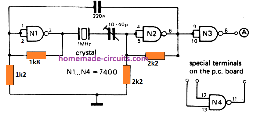
A 3rd NAND gate acts like a buffer at the output of this oscillator output of this oscillator, dividing down by a number of 7490 decade counters.
These incorporate a divide-by-2 stage accompanied by a divide-by-5 stage, that suggests that along with dividing the reference frequency down to 1 Hz in decades, signals of 500 kHz and lower values up to 5 Hz are likewise obtainable.
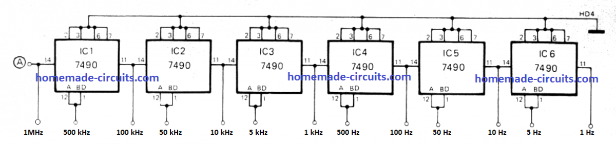
All these signals are specifically useful where gate pulses for counting frequency become necessary. For instance, the 5 Hz output will give you positive pulses of 100 ms width, thus when the frequency of a 10 MHz signal is tested, a gate pulse of this length might allow through 11500,000 cycles of the signal to the counter, presenting a display of 10,00000.
Alternatively, for time calculations the 1 Hz to 1 MHz outputs tend to be more beneficial. As an example, while computing a single second interval, 1,000,000 cycles of the 1 MHz output could be measured, offering a display of 10001300.
PCB Design
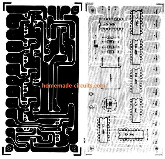
The PCB design and structure is very stream-lined and effectively presented. The outputs are obtainable across the lower edge of the board layout diagram. There exists one extra NAND-gate in the bundle intended for the oscillator, which can be employed as the gate in frequency counter applications.
The wiring contacts to this are introduced at the top right corner of the board. The oscillator frequency could be tweaked to precisely 1 MHz through the trimmer capacitor.
The ideal way of accomplishing this is by using an oscilloscope to examine the 100 kHz output with the 200 kHz Droitwich reception, and applying Lissajous figure. The trimmer must, naturally, be fine-tuned until the Lissajous number stops rotating.
Crystal Controlled Time base Generator
This precision crystal controlled time base circuit is constructed utilizing common easily available CMOS ICs and a inexpensive crystal. This circuit provides the user the configurations for obtaining 50 Hz, 100 Hz or 200 Hz. The 50 Hz reference frequency can be normally applied as a time base for calibrating electronic clocks, frequency meters and many others. IC1 is made up of an oscillator and a 20 divider.
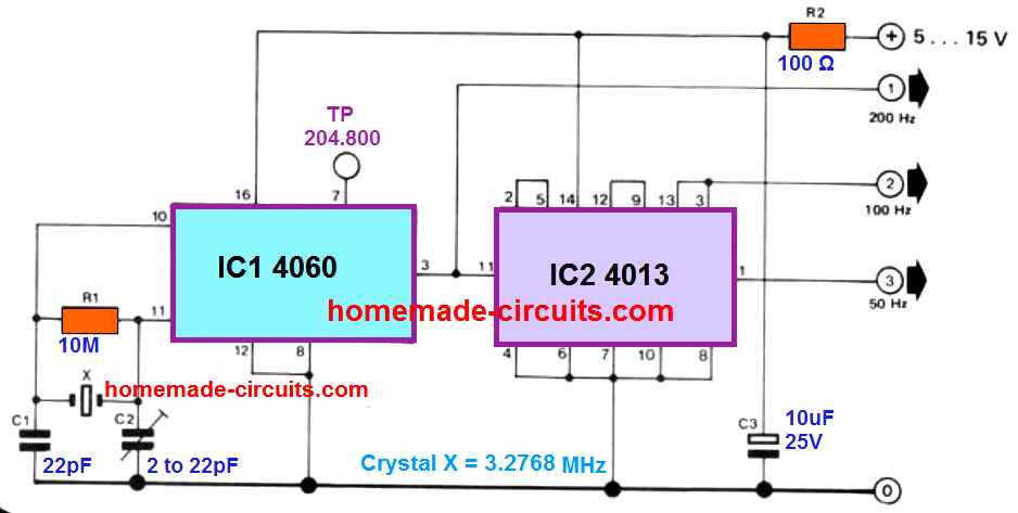
Assuming that the oscillator loop is accurately calibrated through C2, the output at pin 3 (Q14) will generate a 200 Hz square wave. By using the two flip-flops from IC2 rge resulting square wave voltage is subsequently divided by 2 and after that by 4 contributing to a couple of additional outputs of 100 Hz and 50 Hz.
How to Calibrate
The 50 Hz being generated from pin 1. Hobbyists possessing a frequency meter can easily calibrate this crystal controlled time base generator circuit by merely hooking up the meter to pin 7 of IC1 (Q4) and fine-tuning C2 until a display of 204.800 Hz is seen on the meter.
As a topic of curiosity, any user not having a frequency meter probably should not lose heart, because adjusting the trimmer C2 to around at the center point, might be just enough to get adequate precision for the majority of applications.
The 100 Hz output is advantageous for the designing of digital counters.For this particular application we recommend that a 1 : 10 divider IC (like the IC 4518) is attached to the 100 Hz output pin. The power supply specifications are: between 5 .. . 15 V and 0.5… 2.5 mA.
Questions & Answers
Mr Swagatam, thank you for answering my question regarding programmable counters. I will look into this information further.
Bill
My pleasure Bill, have a great weekend…
Mr Swagatam, I understand the dividing by 2 feature and see how 50hz is obtained but how do you divide by a different value than 2? Example: 200 hz (after being divided in chip) would need a division factor of 3.33 to create 60hz.. Are there counter chips that can be programmed for different division factors? Otherwise, I would need to obtain a crystal with a frequency of 983.04 khz. My apologies for bothering you again
No problem Bill, Yes, there are programmable divider ICs such as CD4017, 74HC390, 74LS90, and various prescaler/divider chips that can divide by numbers other than 2. The CD4060 itself only divides by powers of 2 internally.
For obtaining accurate 60Hz or 1-minute timing, we can generally select a crystal frequency that divides evenly into the required output frequency. That is why frequencies like 3.2768MHz or 32.768kHz are commonly used, since they divide very cleanly through binary counters.
Mr Swagatam, Thank you for your unbelievably rapid response to my inquiry. I am a newbie to digital electronics and see I will have to do a lot more learning before I attempt to create my 60 mhz timbase. Is the CD 4060 strictly a oscillator or does it also do internal dividing? The reason I ask is one of your schematics shows a Xtal of 3.2768mhz and a output on pin 3 0f 200hz. this indicates a division factor of 16384. Very confusing to me. I won’t take up any more of your time and appreciate what you have already given me.
Bill Butler Sr.
ARS N2BGR
Thanks for your kind words Bill, you are understanding it correctly. The CD4060 is actually both an oscillator and a binary divider in the same IC. The crystal creates the accurate oscillation frequency, then the internal divider stages automatically divide it down at different output pins.
So with a 3.2768MHz crystal, each output pin gives a lower frequency by powers of 2. That is why one pin can show 200Hz after sufficient division. This built in divider feature is exactly why the CD4060 is so useful for accurate timer applications like your 60 second Geiger counter reset.
I’m looking to make a fairly simple but fairly accurate one minute (60 sec) timebase for a geiger counter counter reset. Would you please advise me what changes I would need to your crystal controlled time base generator? I’ve even been searching to purchase one without luck. Thamk You.
Bill
Hi Bill, this circuit mainly generates a 1MHz crystal controlled clock signal, so for getting an accurate 60 second time base then you would still need some divider stages after it, using CMOS counters like CD4060, CD4040 maybe even 74HC390 stages depending on how you arrange it all.
The crystal side keeps the timing accuracy stable but the divider chain is what slowly brings that frequency down until finally you get something like 1 pulse per minute.
Doing it directly from 1MHz can become a bit lengthy because too many divide stages get involved.
An easier way may be using a 32.768kHz watch crystal together with CD4060 because that crystal is already meant for long timing applications, clocks and things like that so now getting an accurate 60 second output becomes much simpler and fewer divider stages are needed too.
That approach will probably be easier and cleaner for your Geiger counter reset timing setup.
Hi,I am wondering if it is easy to make a 1mhz sounder to treat my deep tissue damage in my leg? I noticed before when I had a wound in my side,and went to a Concert,the Bass was so intense I could not stay in the concert as it was very uncomfortable, the Bass hurt my side! Any sort of Help would be greatly appreciated ????
Sure, it is quite easy. You can try the first circuit from the following link. Just make sure to remove D1 (1N4148) diode connection entirely, and disconnect the buzzer from pin#3 and connect it to pin#7.
https://www.homemade-circuits.com/how-to-make-simple-versatile-timer/
Hello,
how can I make a 120hz transmitter to scare away pigeons, would you have any suggestions?
Thanks.
Ademir (Campinas-SP-Brazil)
Hi,
You can use a 555 based oscillator adjusted to generate 120 Hz. It can be amplified through a transistor and loudspeaker connected with the output of the IC 555.
Hi,
I want to make a white noise generator from 1-100Hz.
Is it possible?
Hi, that may be possible, you can try modifying the circuits provided in the following article:
White Noise and Pink Noise Generator Circuit
Thank you very much for your reply.
I would like to ask two question:
What is the output frequency of the circuit using a Single Transistor?
If I add a low-pass filter or a band-pass filter, could it output white noise of 1-100Hz?
I am not sure how much frequency the single transistor circuit generates, you may have to confirm it using a frequency meter.
Hi,
I need to build a crystal tester to test some 100khz calibration crystals I have.
Most of the circuits I find will only go down to 1Mhz.
Any suggestions?
Thanks
Hi, I have a crystal tester circuit in this blog which you can perhaps try. I guess you can use this circuit to verify your crystals:
https://www.homemade-circuits.com/simple-crystal-tester-circuit/
Thanks Much for responding.
I’ll give it a try.
Walt
Do you know of a simple circuit that will multiply 10 KHz to 100KHz?
You can try the IC 4060. If you feed 10kHz at its pin#11, one of the output pins can be tested for getting 100kHz.
Hello, Swagatam;
My question is in two parts{
1). Would it be possible to attach a digital display to the circuit above,
indicating Hz/Kh/Mh? Possibly with some potentiometers attached to the top of the box, (some examples of digital display and potentiometers would help)?
2). Where can we obtain; board and kit for your design – if possible?
We are in US, (price, delivery if possible).
Brams T.
Hello Brams
1) Yes you can add a frequency counter using the circuits presented in the following articles:
https://www.homemade-circuits.com/5-digit-frequency-counter-circuit/
https://www.homemade-circuits.com/frequency-meter-circuit-using-arduino/
2) I am sorry, a kit option may not be possible from this site, you may have to contact a professional PCB manufacturer for this.
Hello, Swagatam, thank you for prompt reply;
My question is in two parts:
1). Can you receive donations via PayPal?
2). If answer to #1 is yes, also have another question
which will elaborate via email.
Thank you much
Brams T.
Dear Swagatam,
Thank you so much for your suggestion. Yes this is a good idea. I will try it and let you know. Hope it will solve my problem. God bless you.
No Problem Dear Charles, Glad to help!
Hi Mr Swagatam,
I would like to build a circuit which converts 230Vac 50 Hz to 12V pulsating dc (squarewave) at 500Hz. at 1 amp output
Can you suggest such a circuit. I thank you beforehand.
regards
Charles
Hi Mr. Charles, do you want it through a transformer?
Thank you for your kind reply.
It is not important if through a transformer or not. The important thing for me is that the delivery output will be 12 Volts ac square wave with 1 ampere as delivery current. Than with it I like to drive a transformer with input 12 Volts square wave 1 ampere.
Thank you for caring.
Charles
No problem, actually I meant to say, a 220V to 12V adapter will be required for stepping down the mains AC to 12V, this DC could be then used for getting the required 12 V 500 Hz output through any oscillator or astable circuit such as an IC 555, as shown below:
The speaker could be replaced by any other load.
Re 4040 reser problems,
Thank you Swagatam. I will try your tip.
Thanks again.
Harry Brasser
You are most welcome!!
Dear Sir, Can you PLEASE advice. I use a 4040 counter/divider. in an alarm clock, dividing the 50 Herz of the grid by 3000 so I get a pulse every minute. At the count of 3000 we have a negative pulse which goes to the next stage of the circuit but also has to reset its own outputs. (pin 11).
Well at times this negative pulse is not long enough to reset all outputs, some remain low so the next count is going to be shorter. Some IC brands are worse than others
I do not know anybody that can give me some advice. So, whatever you cna advice me will be much appreciated. Thank you so much.
Hello Harry, you can add a buffer gate across each reset pins of the ICs, and join the inputs of all the buffer gates and connect them to the negative pulse source.
The buffer gates can be from the IC 4050 or other
Small correction: the Droitwich emitter (Worcestershire, UK) used to be on 200kHz. Since 1989, it is now on 198kHz. Power is 500 KW, and it is transmitting the BBC N°4 radio program.
Best!
John
Thanks for the information, appreciate it!
Hi Swagatam,
This is a fantastic circuit, Thank you so much.
Is there a way to add successive outputs to this reference signal generator with the same period, duty and amplitude but 0-360 phase angle adjustment? I’ve been trying to get this to work using a 4046 ic but I don’t understand how to stop my circuit feedback loop from locking effectively un-doing my phase offset. I also tried a simple rc delay but found it too frequency dependant resulting in differing degrees of phase offset when the reference signal was changed.
Kindest regards,
Scott
Thanks SCott, Glad you found the article useful. Actually the design is not mine, rather purchased from a contributor, so it may require some study and investigation. If it’s possible I will surely try to update the post with the required details.
Thanks for your reply Swagatam, I still haven’t found a working solution so any suggestions for me to try or ideas for me to investigate would be very much appreciated. I’m stumped.
Thanks Scott, I wish I could help you quickly, but due to lack of time I am unable to look into it, since it might take a lot of time to understand the problem and find a solution.
Dear Swagatam,
Thank you for your 10 band graphic equalizer. Similarly, please also guide for spectrum analyzer to use with graphic equlizer.
Hi Brahmaiha, you can try the following concept for the spectrum analysis
https://www.homemade-circuits.com/simple-audio-spectrum-analyzer-circuit/
Dear Swagatam,
Good Morning,
Very nice of you for sharing your innovations and knowledge with others like dummies and above.I should not say dummies, because some people taking your advice are also may be genius in this field.
I wish to re-master the old movie songs (mono) to high fidelity sound. Please suggest me methodology and some useful circuits for the same.
Thank you dear Brahmaiah, I think there are many mobile apps which can be used for this purpose. Or you can build asound processor sucgh as this:
https://www.homemade-circuits.com/10-band-graphic-equalizer-circuit-for/
and use it to optimize the sound quality to the desired level, and rerecord the output