• Skip to main content
  • Skip to primary sidebar

Homemade Circuit Projects

Get free circuit help 24/7

New Projects | Privacy Policy | About us | Contact | Disclaimer | Copyright | Videos | Circuits for Beginners | Basic Circuits | Hobby Projects | Transistor Circuits | LED Drivers 

You are here: Home / 555 IC Circuits / Illuminated Crosswalk Safety Light Circuit

Illuminated Crosswalk Safety Light Circuit

Last Updated on July 6, 2019 by Swagatam 2 Comments

caution electricity can be dangerous

The article explains a simple illuminated crosswalk safety light circuit for ensuring a safe walking passage for the user amidst heavy traffic. The idea was requested by Mr. John.

Circuit Objectives and Requirements

  1. I recently came upon your website while researching circuits for a hobby project i'm working on. I certainly admire your work.
  2. I was hoping you might be able to put together a simple circuit for an illuminated pedestrian crosswalk system I want to build and install in the car park of my building.
  3. There is heavy traffic and crossing the road at night can be dangerous.
  4. I want to build a lighting system that is push-button activated like a typical pedestrian crossing, but with alternate strobing LED arrays and, most importantly, simultaneously active an array of high-power white LEDS to actually illuminate the crosswalk.
  5. It would be great if the whole thing could be powered by solar so that it could be self-contained and not rely on getting mains power.

The Design

The requested Illuminated crosswalk safety light circuit can be easily built using a few 555 ICs, and some passive electronic components as shown below:

Illuminated Crosswalk Safety Light Circuit

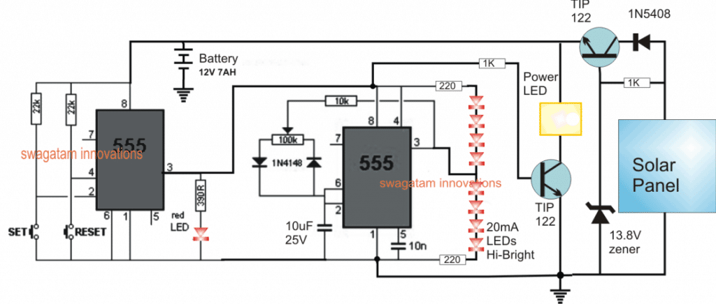
Referring to the figure above, the left side IC 555 is configured as a bistable for enabling the required push-button operated ON/OFF actions. The "SET" button initiates the IC 555 and causes a high logic to appear at its pin#3, while the "RESET" button deactivates the IC operation and switches OFF pin#3 logic to a zero.

In the activated mode the bistable stage powers the right side IC 555 stage which is wired as a standard astable circuit for generating a flashing or blinking output at its pin#3 which in turn causes the attached red LEDs to light up with a rapid flashing effect, simulating a strobing light.

The strobing rate can be controlled through the 100k pot associated with the astable IC 555 stage.

Along with the activation of the the strobing lights, the bistable stage also triggers and illuminates a power LED via a driver transistor TIP122, so that the crosswalk could be illuminated with sufficient light for the user.

Once the user has crossed the path, pressing the RESET button toggles off the whole system until the SET button is pressed yet again by some other pedestrian.

In order to make the system self contained, this illuminated crosswalk safety circuit employs an appropriately rated solar panel and a compatible 12V rechargeable battery for powering the circuit and the LeDs.

During day time the battery is charged, and when darkness sets in, the battery reverts its power for the intended crosswalk safety light operations.

The battery and the panel specifications will depend on the type of LEDs used for the purpose.

The emitter-follower transistor configuration attached with the solar panel ensures a controlled charging for the battery and never allows it charge over a predetermined level, as set by its base zener diode.

You'll also like:

  • 1.  Pressure Cooker Whistle Counter Circuit
  • 2.  Room Air Ionizer Circuit – For Pollution Free Living
  • 3.  High Current Wireless Battery Charger Circuit
  • 4.  Motorcycle Button Start Locking Circuit
  • 5.  How to Generate Pure Oxygen and Hydrogen at Home
  • 6.  Simple Buck-Boost Converter Circuits Explained

About Swagatam

I am an electronic engineer (dipIETE ), hobbyist, inventor, schematic/PCB designer, manufacturer. I am also the founder of the website: https://www.homemade-circuits.com/, where I love sharing my innovative circuit ideas and tutorials.
If you have any circuit related query, you may interact through comments, I'll be most happy to help!

Reader Interactions

Comments

    Have Questions? Please post your comments below for quick replies! Comments should be related to the above artcile Cancel reply

    Your email address will not be published. Required fields are marked *

  1. Quadri says

    February 3, 2019

    Hello sir and thanks for the good work.
    Can this circuit be modified to an automatic changeover switch between generators and mains such that whenever mains is restored the changeover system will turn off the generator.

    Thanks sir

    Reply
    • Swagatam says

      February 3, 2019

      Hello quadri, I already have the required circuit in this website, you can checkout here:

      https://www.homemade-circuits.com/?s=generator+mains+changeover

      Reply

Primary Sidebar

Calculators

  • 3-Phase Power (15)
  • 324 IC Circuits (19)
  • 4017 IC Circuits (52)
  • 4060 IC Circuits (25)
  • 555 IC Circuits (98)
  • 741 IC Circuits (19)
  • Arduino Engineering Projects (83)
  • Audio and Amplifier Projects (114)
  • Battery Chargers (82)
  • Car and Motorcycle (94)
  • Datasheets (46)
  • Decorative Lighting (Diwali, Christmas) (33)
  • Electronic Components (100)
  • Electronic Devices and Circuit Theory (36)
  • Electronics Tutorial (116)
  • Fish Aquarium (5)
  • Free Energy (34)
  • Fun Projects (13)
  • GSM Projects (9)
  • Health Related (20)
  • Heater Controllers (29)
  • Home Electrical Circuits (102)
  • How to Articles (20)
  • Incubator Related (6)
  • Industrial Electronics (28)
  • Infrared (IR) (40)
  • Inverter Circuits (98)
  • Laser Projects (12)
  • LED and Light Effect (93)
  • LM317/LM338 (21)
  • LM3915 IC (25)
  • Meters and Testers (65)
  • Mini Projects (148)
  • Motor Controller (67)
  • MPPT (7)
  • Oscillator Circuits (26)
  • PIR (Passive Infrared) (8)
  • Power Electronics (34)
  • Power Supply Circuits (77)
  • Radio Circuits (10)
  • Remote Control (48)
  • Security and Alarm (61)
  • Sensors and Detectors (120)
  • SG3525 IC (5)
  • Simple Circuits (75)
  • SMPS (29)
  • Solar Controllers (60)
  • Timer and Delay Relay (53)
  • TL494 IC (5)
  • Transformerless Power Supply (8)
  • Transmitter Circuits (40)
  • Ultrasonic Projects (16)
  • Water Level Controller (45)

Calculators

  • AWG to Millimeter Converter
  • Battery Back up Time Calculator
  • Capacitance Reactance Calculator
  • IC 555 Astable Calculator
  • IC 555 Monostable Calculator
  • Inductance Calculator
  • LC Resonance Calculator
  • LM317, LM338, LM396 Calculator
  • Ohm’s Law Calculator
  • Phase Angle Phase Shift Calculator
  • Power Factor (PF) Calculator
  • Reactance Calculator
  • Small Signal Transistor(BJT) and Diode Quick Datasheet
  • Transistor Astable Calculator
  • Transistor base Resistor Calculator
  • Voltage Divider Calculator
  • Wire Current Calculator
  • Zener Diode Calculator

© 2023 · Swagatam Innovations