• Skip to main content
  • Skip to primary sidebar

Homemade Circuit Projects

Get free circuit help 24/7

New Projects | Privacy Policy | About us | Contact | Disclaimer | Copyright | Videos | Circuits for Beginners | Basic Circuits | Hobby Projects | Transistor Circuits | LED Drivers 

You are here: Home / Home Electrical Circuits / Automatic Door Lamp Timer Circuit

Automatic Door Lamp Timer Circuit

Last Updated on March 13, 2019 by Swagatam Leave a Comment

caution electricity can be dangerous

The article explains a simple automatic door light timer circuit which activates every time the door is opened, and switches OFF after a predetermined time if the door is kept open for too long. The circuit was requested by one of the avid readers of this blog, Mr. Juan. Let's learn more.

Technical Specifications:

I always find your blog very interesting.

I want to know if this would be possible

I have a cabinet in with I put a magnetic switch with normally closed and normally open contacts. (today, I only use one of them)

Today, when you open the door, the light that is on top turns on

I would change the circuit so that:

1. Open the door once so the circuit is ON, after a given time, the light turns off (although the door hasn't been closed and is opened). If I ever want to turn on the light, I have to close the door and reopen it.

2. add a LDR to turn on the light ONLY if there isn't sunlight in the room. With LDR in series with the load is enough?

The system is 12V. Should I use the famous 555? (all I've seen is with tiggers (push buttons), which is not my case)

Thank you.

The Design

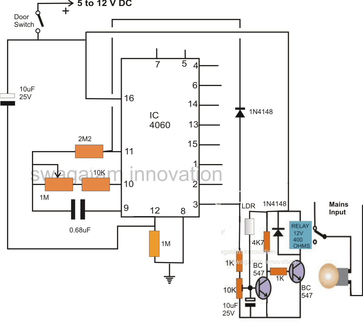
Instead of 555 IC, a 4060 IC has been used here due to it's better accuracy.

The IC 4060 is configured in its standard delay timer mode, where the 1M pot and 0.68uF decides the length of the time delay.

The door switch is set in such a way that it closes when the door opens.

The 10uF capactor at the supply resets pin#16 so that the timer initiates the counting process from zero.

During this period pin#3 stays at logic zero, keeping the first BC547 switched off, which in turn switches ON the relay driver and the lamp.

If the door stays open until the timer delay lapses, pin#3 goes high switching ON the first BC547 and consequently switching OFF the relay driver and the lamp.

Also, at the same time the positive from pin#3 reaches pin#11 of the IC via the connected 1N4148 diode which latches the entire circuit.

This renders the lamp permanently ON,

In order to switch OFF the lamp, the door will need to be closed now.
An LDR at the base of the first transistor makes sure that this transistor switches ON when there's ample ambient light.

In the above situation the relay driver transistor is held switched OFF, which in turn keeps the lamp switched OFF.

Time Delay Formula

For calculating the output time delay, you can use the following formula:

f(osc) = 1 / 2.3 x Rt x Ct

2.3 is a constant term here.

The oscillator will work with proper results only when the part values are selected as per the following conditions:

Rt << R2 and R2 x C2 << Rt x Ct.

You'll also like:

  • 1.  10/12 watt LED Lamp with 12 V Adapter
  • 2.  Delay based Motor Speed Controller Circuit – Timer Controlled
  • 3.  Bathroom Lamp Timer Circuit with Buzzer
  • 4.  Using an NTC Thermistor as a Surge Suppressor
  • 5.  Simple Hobby Circuit Projects
  • 6.  Automatic Voltage Regulator (AVR) Circuit

About Swagatam

I am an electronic engineer (dipIETE ), hobbyist, inventor, schematic/PCB designer, manufacturer. I am also the founder of the website: https://www.homemade-circuits.com/, where I love sharing my innovative circuit ideas and tutorials.
If you have any circuit related query, you may interact through comments, I'll be most happy to help!

Have Questions? Please Comment below to Solve your Queries! Comments must be Related to the above Topic!!

Subscribe
Notify of
0 Comments
Inline Feedbacks
View all comments

Primary Sidebar

Calculators

  • 3-Phase Power (15)
  • 324 IC Circuits (19)
  • 4017 IC Circuits (52)
  • 4060 IC Circuits (25)
  • 555 IC Circuits (98)
  • 741 IC Circuits (19)
  • Arduino Engineering Projects (83)
  • Audio and Amplifier Projects (114)
  • Battery Chargers (82)
  • Car and Motorcycle (94)
  • Datasheets (46)
  • Decorative Lighting (Diwali, Christmas) (33)
  • Electronic Components (100)
  • Electronic Devices and Circuit Theory (36)
  • Electronics Tutorial (116)
  • Fish Aquarium (5)
  • Free Energy (34)
  • Fun Projects (13)
  • GSM Projects (9)
  • Health Related (20)
  • Heater Controllers (29)
  • Home Electrical Circuits (102)
  • How to Articles (20)
  • Incubator Related (6)
  • Industrial Electronics (28)
  • Infrared (IR) (40)
  • Inverter Circuits (98)
  • Laser Projects (12)
  • LED and Light Effect (93)
  • LM317/LM338 (21)
  • LM3915 IC (25)
  • Meters and Testers (65)
  • Mini Projects (148)
  • Motor Controller (67)
  • MPPT (7)
  • Oscillator Circuits (26)
  • PIR (Passive Infrared) (8)
  • Power Electronics (34)
  • Power Supply Circuits (77)
  • Radio Circuits (10)
  • Remote Control (48)
  • Security and Alarm (61)
  • Sensors and Detectors (120)
  • SG3525 IC (5)
  • Simple Circuits (75)
  • SMPS (29)
  • Solar Controllers (60)
  • Timer and Delay Relay (53)
  • TL494 IC (5)
  • Transformerless Power Supply (8)
  • Transmitter Circuits (40)
  • Ultrasonic Projects (16)
  • Water Level Controller (45)

Calculators

  • AWG to Millimeter Converter
  • Battery Back up Time Calculator
  • Capacitance Reactance Calculator
  • IC 555 Astable Calculator
  • IC 555 Monostable Calculator
  • Inductance Calculator
  • LC Resonance Calculator
  • LM317, LM338, LM396 Calculator
  • Ohm’s Law Calculator
  • Phase Angle Phase Shift Calculator
  • Power Factor (PF) Calculator
  • Reactance Calculator
  • Small Signal Transistor(BJT) and Diode Quick Datasheet
  • Transistor Astable Calculator
  • Transistor base Resistor Calculator
  • Voltage Divider Calculator
  • Wire Current Calculator
  • Zener Diode Calculator

© 2023 · Swagatam Innovations

wpDiscuz