This circuit is actually a little more advanced LED chaser scanner circuit using two 74LS164 Shift Register ICs together with one NE555 Timer, and yep the light effect looks somewhat similar to those old Knight Rider or Mustang scanner lights which move from sides toward center.
The LEDs are arranged in two strips, or sometimes two halves of one strip, so now visually the lights seem to travel inward from both outer ends.
Main Working Principle
Mainly we have three sections here somehow.
One IC555 clock pulse generator section. Then two cascaded 74LS164 shift registers. And one small switching reset section using T1 and S1.
Circuit Diagram
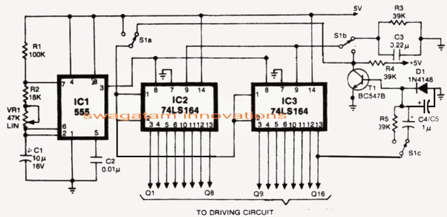
Clock Generator Using IC555
The IC 555 Timer here works like astable oscillator mode, meaning it keeps generating square wave pulses continuously without stopping.
Those pulses go into pin 8 of both shift registers so each new pulse pushes one logic HIGH forward by one step.
Scanning speed depends on the RC timing parts around the 555. So if resistance or capacitance becomes higher then scanning slows down and if values become lower then movement becomes faster. That potentiometer there simply lets us adjust this speed manually a bit.
So the 555 is kind of acting like heartbeat of the whole scanner circuit.
How the 74LS164 Shift Registers Work
Each 74LS164 has 8 outputs and since we use two ICs together then total outputs become 16, so now 16 LEDs can be controlled. Every incoming clock pulse shifts the HIGH condition to next output.
Like first pulse makes Q1 HIGH, next pulse moves it to Q2, then Q3 and it keeps going like that.
Previous outputs stay latched HIGH too therefore LEDs appear to fill one by one progressively instead of only one LED moving alone.
LED Physical Arrangement
Interesting trick is used in the physical LED arrangement because outputs are not placed in straight sequential order physically.
Q1 to Q8 are arranged from left side toward center.
Then Q9 to Q16 come from right side toward center.
Q8 faces center from left side and Q16 faces center from right side. Hence visually both sides seem moving inward together, which creates that scanner illusion effect.
MODE 1 Operation
In Mode 1 the LEDs keep turning ON gradually from outer ends toward center.
First only outer LEDs glow, then more pulses keep filling inward and finally all LEDs become ON.
When HIGH finally reaches pin 16 or Q16 then T1 switches ON.
T1 immediately resets both shift registers. So now all LEDs suddenly switch OFF together at once and whole cycle starts again from beginning.
Effect becomes something like outer side filling inward, all ON, then instant OFF.
MODE 2 Operation
Mode 2 is slightly different and maybe looks more interesting visually.
Initially LEDs fill inward same as before but when HIGH reaches Q16 then T1 switches ON again and changes logic condition at pins 1 and 2 of the shift registers.
Now instead of HIGH bits entering the registers, LOW bits start entering. So reverse effect begins.
LEDs now start turning OFF progressively, again from outer ends toward center.
Something like this happens:
1111111111111111
0111111111111110
0011111111111100
0001111111111000
and slowly everything becomes OFF.
Then cycle starts again.
So unlike Mode 1 instant reset here LEDs clear inward gradually which looks smoother somehow.
Role of Transistor T1
T1 mainly acts like automatic end sequence detector and control switch. When Q16 becomes HIGH then T1 turns ON and changes the logic conditions. Depending on selected mode it either resets ICs immediately or injects LOW bits for gradual turn OFF action.
So T1 basically detects when sequence has reached final stage.
Why Two Modes Are Needed
Mode 1 gives sharper flashing type scanner look, more aggressive kind of effect because reset happens instantly.
Mode 2 looks smoother and more cinematic since LEDs clear progressively instead of suddenly disappearing.
Many people usually like this second mode more for decorative scanners.
Why the Circuit Looks Attractive
The nice visual movement happens because LEDs switch sequentially and both directions move symmetrically toward center.
Human eyes also retain light briefly, persistence of vision thing. Thus movement appears smooth instead of broken blinking.
Power Supply is Important
Since 74LS164 is LS TTL type IC, supply should ideally stay regulated at 5V. LED current also should remain within safe IC output limits.
If many bright LEDs are used then transistor drivers may become necessary, especially in automotive use where brighter LEDs and higher current are common.
Practical Applications
These kinds of scanner circuits are often used in decorative car lights, Knight Rider style scanners, display systems, DJ lighting, toys, sequential indicators and similar moving light projects.
Circuit is actually simple digitally but visual effect looks quite attractive when LEDs start moving inward from both sides like that.


Questions & Answers
LED chase once after all LED are glow.please share circuit diagram using 74LS164
Yes it will do that exactly…