This article explains the main specifications, pinouts and application related information regarding the transistor NPN BJT 2N2222, 2N2222A, and also its complimentary PNP pair 2N2907 BJT
Introduction
In one of my earlier posts I have explained regarding a few low signal type of transistors like BC547, BC557 etc. Here we are going to study the ubiquitous 2N2222 family of transistors and also regarding implementing their specs and thresholds.
The transistor 2N2222 is one of the important and very commonly used transistor type which finds numerous switching application in electronic circuts.
The main feature of this transistor is its ability to handle relatively high magnitudes of currents compared to other simiar small signal types of transistors.
Typically, a 2N2222 transistor is able to switch 800 mA of load current through it, which may be considered quite high compared to the miniature size owned by these devices.
High current switching capability also makes this device ideally suited for linear amplifier applications.
The main characteristics of this device may be understood with the following points:
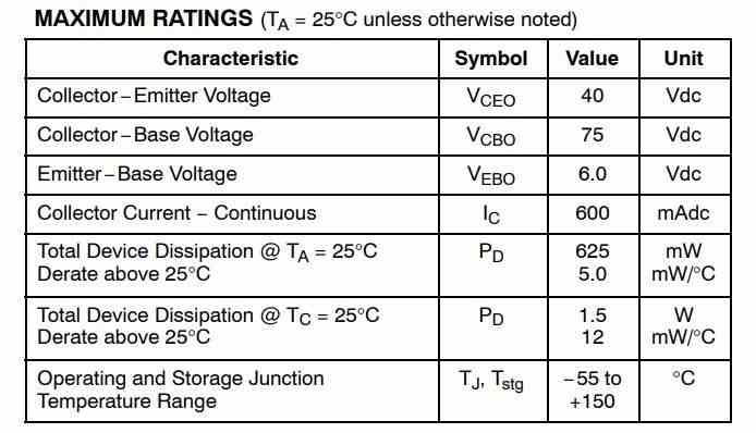
The transistor 2N2222 or 2N2222A are NPN types and has the following electrical parameters:
- The device’s maximum voltage tolerance (breakdown voltage) across its collector and base is 60 volts for 2N2222 and 75 volts for 2N2222A, with the emitters kept open.
- With their base open, the above tolerance across their collector and emitter leads is 30 volts for 2N2222 and 40 volts for 2N2222A.
- As expressed earlier, the maximum current that can be applied across the transistors collector and emitter, via a load is not more than 800 mA.
- Total power dissipation of the device should not exceed above 500 mW.
- hFE or the dC current gain of 2N2222 transistors will be around 75 minimum, at voltages near 10, with 10 mA collector current.
- Maximum frequency handling capacity or the transition frequency is 250 MHz for 2N2222 and 300 MHz for 2N2222A.
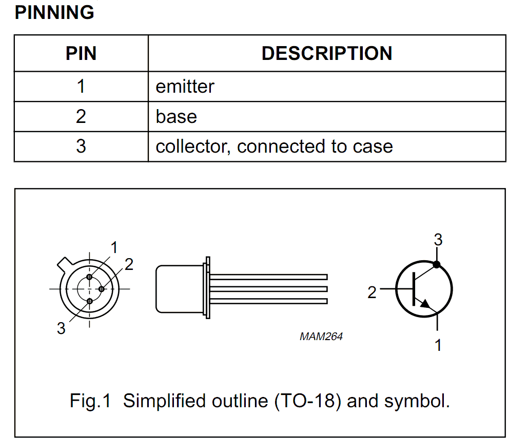
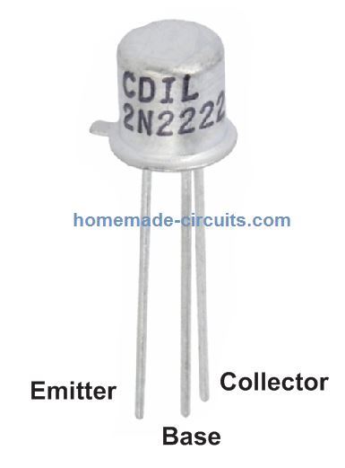
2N2222 Pinout Details
· The base-emitter saturation voltage for 2N2222 is typically 1.3 volts @ 15 mA, when the collector current is around 150 mA. With collector current exceeding 500 mA, the base optimal trigger voltage becomes 2.6 volts. For a 2N2222A, the figures are 1.2 and 2 volts respectively.
Configuring the device practically in electronic circuits for any relevant application:
This may be done by following the below explained steps:
The pin out or the leg that’s marked emitter must be connected to the negative line of the supply rail.
The load which needs to be switched must be connected in between the collector of the transistor and the positive supply, that is, the positive lead of the load goes to the positive supply while the other lead of the load gets connected to the collector lead of the transistor.
- The base goes to the source voltage or the triggering voltage via a current limiting resistor.
- The value of the current limiting resistor may be calculated by using the formula explained at the end of this article.
- The transistor 2N2907 is complementary pair for 2N2222 and has identical specs as above, however being a PNP type the associated polarities are exactly opposite.

Questions & Answers
From the datasheet, why there are two Pd (Total Power Dissipation)?
Total Device Dissipation @ T_A = 25°C
P_T = 500 mW (0.5W)
T_A (Ambient Temperature) means that the transistor is operating in free air without any heatsink.
The maximum power the transistor can safely dissipate in open air is 500 mW before too much heating occurs.
Total Device Dissipation @ T_C = 25°C
P_T = 1.0 W
T_C (Case Temperature), it means that the transistor’s case is kept at 25°C, commonly using an heatsink.
With proper heatsinking, the transistor can safely dissipate up to 1W without overheating.
Same problem i need to in which device this is used
for all circuits which are rated to work with specifications as indicated in the above article.
i need you to tell me in which appliances these 2n2222a transistor are found please tell me today only