The post presents a simple transformerless red LED sign circuit which can be made even by a novice. The circuit uses only a few high voltage capacitors, two resistors, and a few red LEDs.... nothing more. The circuit idea and the images were submitted by Mr. John Hungerford.
The following email was sent to me by Mr. John, I have explained all the details about the proposed red led sign circuit idea, sent by Mr. John.
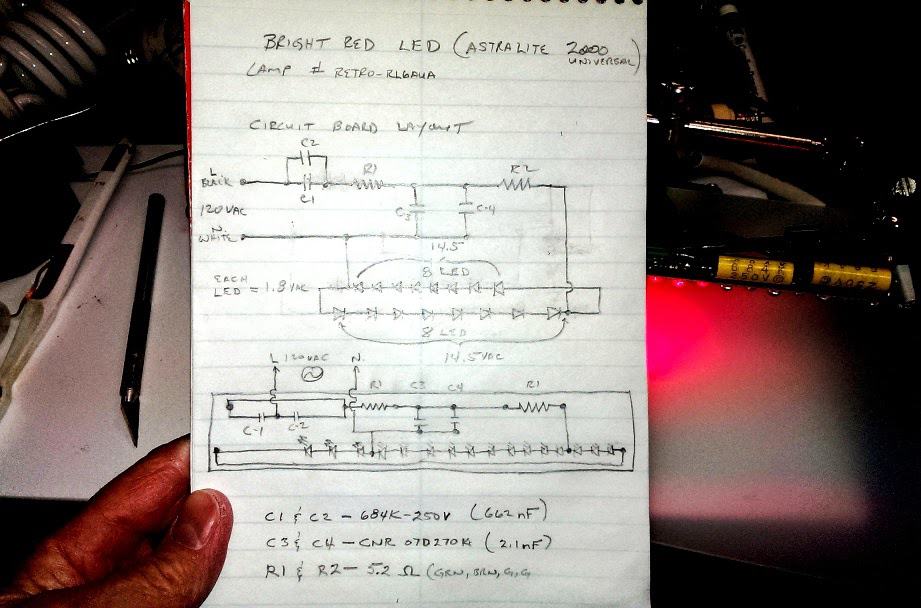
Technical Specifications
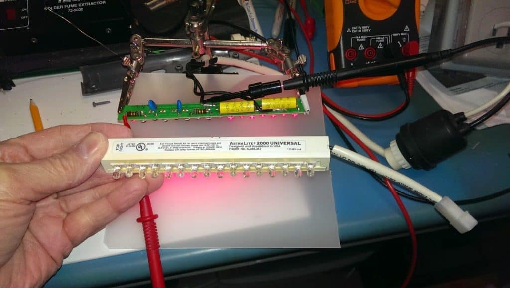
I had this bright red LED EXIT commercial old sign given by my son-in-law who works in electrical field. He always finds something useful and saves just anything
I have used its components and parts for the red LED sign project.
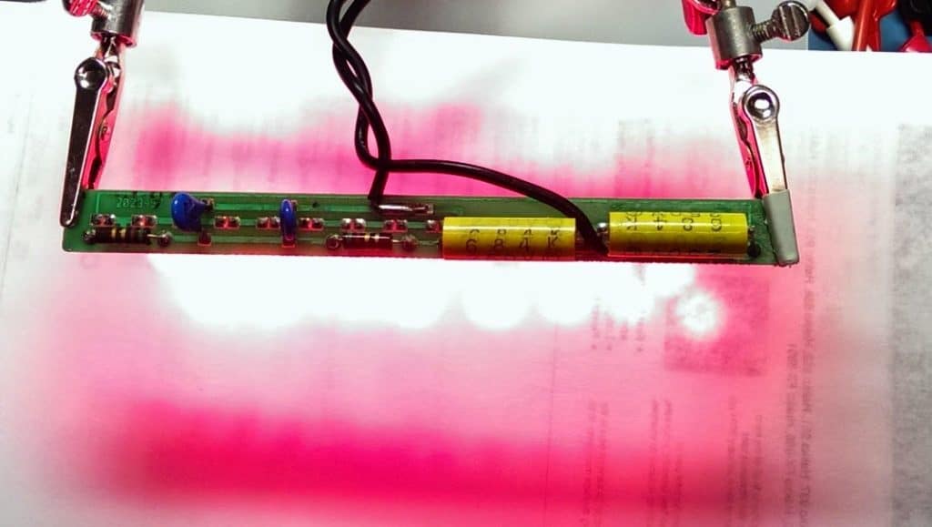
Now I have removed the enclosed 120/277 vac transformer and taken out 16 LEDs out of the total 10 sets of many red LEDs in series and assembled them over a circuit board. This can go without transformer as you will see this pictures and video.
I’m learning and trying to understand how the voltage works. I’m not perfect in such layout and drawings. In this drawing there are two perspectives: the bottom drawing is what is done over the circuit board.
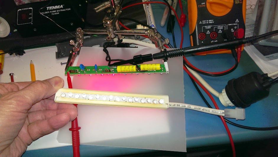
My question is how the voltage drop from 120 to 14.5 vac handle it without any heat while LEDs light stay on? Test red probes of DMM were measured on R2 and LED and black probe on white (neutral) is 14.5 vac.
I thought these caps were supposed to increase voltage. So this capacitors C1 and C2 I measure is 662nF are parallel are like resistors that split and reduce voltage, right?.
I took out one LED for testing my home made LED tester. Each Red LED is 1.8 volt times 8 LED is 14.5 vac. I see 16 total LED half go that using 14.5 vac.
Now I find it amazing how without a transformer it stays switched on and can withstand 120 vac directly without transformer.
Can you explain how this voltage/current flow to get voltage reduced by only four capacitors and two resistors to light up 16 LEDs. See my paper written down on bottom with the list of components. The components are old but it is working great as you would see in the video.
Also I haven’t tested the design on my scope yet, if the sine wave showing any different?
I hope this design is safe to use.
So now looking for an idea of what project I can use it:)
Could not send video.......it's too large.
Only Pictures:(
Thanks,John Hungerford
(deafguy)

Solving the Circuit Query
Thanks for the nice images, I appreciate your work. Here's the explanation:
What you have made is a simple capacitive power supply, where the capacitors act like resistances (for AC) and drop the voltage/current to the required limits of the LEDs.
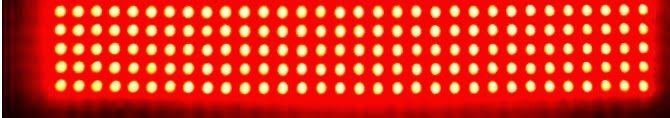
Since 5mm red LEDs are able to produce bright illuminations even at voltages as low as 2V and @10mA, your circuit is able to produce those dazzling results even without a transformer.
In your red LED sign circuit you have connected two LED strings back to back with opposite polarities making it possible for both the halves of AC cycles to pass through the LED strings.
This configuration has allowed the elimination of the diodes as rectification of the AC is done by the LEDs itself in the course of their switching.
The positive cycles find its way through the upper LED string while the negative cycles pass through the lower LED string.
This actually means that both the strings are never illuminated together, rather are switched ON alternately.
Since this happens 50 times per seconds, we are unable to make out the alternate switching due to persistence of vision, and find all the LEDs switched ON continuously.
However C3 and C4 may not be required as these would only reduce the available current for the LEDs and make them dimmer.
I hope the above explanation will solve your curiosity.
Best Regards.


Need Help? Please Leave a Comment! We value your input—Kindly keep it relevant to the above topic!