In this article I have explained an innovative way of driving more than a hundred white LEDs from a 6 volt battery. The circuit utilizes the IC 555 for driving a step up transformer, whose output is finally used for illuminating the LEDs. A special PWM configuration makes the circuit much power efficient.
Main Stages of the Design
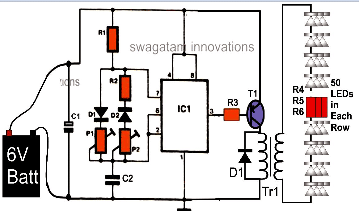
The main stages of this 6V 100 LED pwm driver using IC 555 are an astable multivibrator stage configured with PWM control facility and an output transformer step-up stage.
The pulses generated by the pwm stage is used for dumping and saturating the input winding of the transformer, which get amplified to the specified levels at the output winding of the transformer driving the bunch of LEDs connected there.
Using IC 555 for PWM Control
The IC 555 is wired up in its most usual configuration, as an astable multivibrator.
Everything about the circuit looks pretty common as the pin outs of the IC is configured with its usual format, except for the two diodes and a couple of presets which makes the circuit a bit different from the typical 555 astable set ups.
The inclusion of the two diodes and the presets here enables the control of the pulse formations discretely.
This control of the pulses is termed PWM or pulse width modulation.
The PWM implementation in the circuit can be understood by refering the diagram and with the following points:
Initially when the circuit is powered, pin #2 which is trigger pin of the IC, goes low, with the capacitor in the discharging mode, holding the output low.
Once C2 is fully discharged, flips the output which was initially low to high.
At this point the capacitor C2 begins charging through D1 and P1, until the voltage across C2 reaches 2/3rd of the supply voltage, when pin #6 of the IC is switched, resulting the output and pin #7 to go low yet again.
Circuit Diagram
The above procedure repeats, causing sustained oscillations at the output.
However since the charging and discharging periods of C2 directly corresponds to the output periods of the pulses, it simply means that by varying or controlling the charging and discharging of C2 separately, we should be able to dimension the output pulses correspondingly.
The pots or the presets P1 and P2 are exactly placed for these adjustments and hence constitutes the PWM function.
The PWM application contributes to another important function for the present application.
By suitably optimizing the pulses, we can set the circuit to a most economic position for obtaining optimum brightness from the LEDs at relatively lower battery consumption.
The output from the IC is taken from its pin number three and used for driving as power transistor.
Since the collector of the power transistor is joined to the secondary (low voltage) winding of an ordinary AC-DC transformer, the entire supply voltage is dumped periodically into this section of the transformer inductor.
As anticipated, this pulsed voltage which is forced into the secondary winding induces a proportional magnitude of voltage into the primary winding of the transformer.
The process is entirely reversed as compared to the situation when the transformer is used with its normal AC-DC adapter applications.
The voltage is stepped-up rather than stepping down to about 230 volts which happens to be its normal primary winding specification.
This stepped up voltage available at the free winding ends of the transformer is actually used for driving a large number of LEDs which are wired up through long series and a few parallel connections.
How the Circuit is Powered
The proposed 6V 100 LED Driver circuit is powered by a SMF battery of 6 volts and around 4 Ah of capacity.
The power of the battery may appear to be quite high but the parameters are not suitable for driving a very high number of LEDs.
I have already discussed about this issue in number of my earlier posts.
Basically LEDs are voltage driven devices and not current, i.e. if the applied voltage satisfies the forward voltage, the LEDs get illuminated with nominal current levels and on the contrary if the voltage does not match the LEDs forward voltage spec, then the LED refuses to light even if the applied current is made 100 times the saturating value.
Another factor associated with LEDs is that, these devices can be run in series with its minimum specified current levels.
That means if the voltage of the series matches the total forward voltage of the series, the current required would be just around the magnitude that would be required for lighting a single LED.
This parameter rather feature with LEDs wiring becomes imperative when the source voltage is quite low.
Thus for driving many numbers of LEDs as discussed for the proposed circuit from a 6 volts source, the above rule becomes necessary and has been effectively employed.
Parts List
The following parts will be required for making the above PWM LED driver circuit:
All the resistors are ¼ watt unless otherwise specified.
- R1 , R2 = 1 K = 2
- R3 = 10 K = 1
- R4, R5, R6 = 100 Ohms = 3
- P1, P2 = 100 K = 2
- C1 = 10 uF / 25 V = 1
- C2 = 0.001 uF, ceramic disc = 1
- IC = LM 555 = 1
- T1 = TIP 127 = 1
- TR1 = sec. – 0 – 6 V, prim. – 0 – 230 V, 500mA = 1
- Battery – 6 volts, 4 AH, SUNCA type =1
- PCB – Veroboard, cut according to the required size = 1
- LEDs – 5 mm, white, high bright, high-efficiency.
- CAUTION - THE CIRCUIT IS BASED ON THE ASSUMPTIONS MADE BY THE AUTHOR AND HAS NOT BEEN PRACTICALLY VERIFIED, VIEWERS DISCRETION IS ADVISED.


Questions & Answers
Hi,
In this circuit, 4 rows of 50 LED’s each, right?
You have, for what I can see, 3 rows, of 50 LED each, that gives 150 LED’s.
If each row is about 1A (50x20mA), I can replace all 50 LED’s by a 5W LED.
Are my assumptions correct?
Best Regards.
Nelio
Hi, current in a series string is always the same. So for each vertical column the current will be 20 mA only.
Hi Swagatam, I want to power couple of 3 watt 220 volt AC led bulbs (which are commercially available) from a DC power source which gives 5 volt DC @ 500 mA as the output. Can I connect two such 3 watt led bulbs in parallel to your: 'Illuminating 100 LEDs from 6 Volt Battery Circuit' and will it give me the same brightness as it does when running from the mains supply? If that is not possible, can you please suggest a suitable circuit which will be low in cost and can give the desired output for 1 or 2 hrs with minimal components and current consumption? Regards, Raj.
Hi Raj,
you can use the above, but the brightness could be less due to the involvement of an iron core trafo… there's even a simpler design than the above which can seen in the following article:
https://www.homemade-circuits.com/2013/03/how-to-convert-12v-dc-to-220v-ac-using.html
6V can also be used for getting 220V from this circuit, basically the coil turns determine the maximum output voltage.
you can ignore and remove all that's shown at the right side of the mosfet, along with the BC547 transistor.
the coil could be wound over a ferrite ring or a ferrite rod using a 0.3mm super enameled copper wire
Sri. Majumdar,
How does the battery get charged?
svs
good evening sir! do you have a simple 6 volt led flasher circuit?
Jindro, you can try the designs presented in the following article:
https://www.homemade-circuits.com/how-to-make-any-light-strobe-light/
Sir, is there any dmx controlling board circuit as i wanted to controll rgb led strips using dmx controller
Raja, I do not have a dmx controller circuit at the moment, I'll try to find it…. although a simpler version can be studied in this article:
https://www.homemade-circuits.com/2015/01/rgb-led-flasher-circuit.html
Sir can we use a 4 volt 3 Ah battery for this circuit and if yes what changes do we have to make.
Rahul, yes you can use it. No changes would be required.
Hello sir, please I have Purchase all the components but I am confused about how the resistors are connected to the LEDs. Please could you kindly expand the diagram at the point where the LEDs are connected to the resistors..i have 100 LEDs
helo 1world
the resistors are connected in series with the LEDs.
you will have make one modification in the circuit.
Don't use the mentioned transformer for TR1.
Replace it by a coil made by winding 200 turns over a ferrite rod. The wire can be any thin enamelled copper wire which are used in step down transformers.
This coil must be connected across the collector of the transistor and ground.
Don't include the diode across the coil.
Now simply connect the LEDs as shown directly parallel to the above coil.
hi sir
i want to make light up around 50 led's from a 5volt dc supply. can u plz help me building it?
you are welcome Anirudh.
Thanks a lot sir. It helped me a lot.
Anirudh, you will have to connect all the LEDs in parallel with one resistor for each LED.
For 6v supply the value of the resistors will be 150 ohms 1/4 watt
Sir I want to use the regular 5 mm white led's.
The circuit u designed "100 led's from 6 volt" is a nice circuit but I guess it will be caught flickering in the video frames as I am making this for my videography work.
So am looking for a 5-6 volt battery powered circuit to light around 50 led's.
hi Anirudh
what type of LED do you want use? please provide the current and voltage rating of the LEDs.
hello sir
i will be glad if u help me in guiding as in how to design a 5 volt led circuit comprising of about 59 led's, with a dimmer
Hi Kiran,
If you are finding the above circuit difficult, you can try the following circuit, it's similar but does not incorporate a transformer rather a coil wound over a ferrite rod. Use 100 turns of any thin enameled copper wire over a 5 inches ferrite rod:
https://www.homemade-circuits.com/2013/03/how-to-convert-12v-dc-to-220v-ac-using.html
You can remove all components that's shown at the right hand side of the mosfet and at its gate.