• Skip to main content
  • Skip to primary sidebar

Homemade Circuit Projects

Need circuit help? Post them in the comments! I've answered over 50,000!

Blog | Categories | About | Hire Me | Contact | Calculators-online
You are here: Home / Electronics Theory / How to Understand IC 4017 Pinouts

How to Understand IC 4017 Pinouts

Last Updated on June 7, 2026 by Swagatam 246 Comments

The IC 4017 can be considered as one of the most useful and versatile chip having numerous electronic circuit applications.

Table of Contents
  • About IC 4017
  • Understanding pinout Function of IC 4017
    • What do Logic High, Logic Low Mean
    • What is the Output pin Sequencing order?
    • Why Pin 15 Should be Grounded
    • Pin 14 Needs External Frequency (Clock Signal)
    • Pin 13 is Opposite of Pin 14
    • How Pin 15 Works Like reset Pin
    • Using Pin#15 to Reduce the Number of Output Sequence
      • Ground pin and Carryout Pin
    • Basic IC 4017 Pinout Connection Diagram
    • Application LED Chaser Circuit using IC 4017 and IC555
    • IC 4017 Working Simulation
    • How to Cascade Two 4017 ICs for Getting 17 Sequencing Outputs
    • How to Cascade Three IC 4017 for Getting 25 Sequencing Outputs
    • How to Cascade Four IC 4017 to get 33 Sequencing Outputs
    • Sources

About IC 4017

Technically it is called the Johnsons 10 stage decade counter divider. The name suggest two things, it’s something to do with number 10 and counting/dividing.

The number 10 is connected with the number of outputs this IC has, and these outputs become high in sequence in response to every high clock pulse applied at its input clock pin out.

It means, all its 10 outputs will go through one cycle of high output sequencing from start to finish in response to 10 clocks received at its input (pin#14). So in a way it is counting and also dividing the input clock by 10 and hence the name.
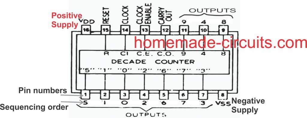
4017 pinouts

Complete Datasheet

Understanding pinout Function of IC 4017

Let’s understand the pin outs of the IC 4017 in details and from a newcomer’s point of view: Looking at the figure we see that the device is a 16 pin DIL IC, the pin out numbers are indicated in the diagram with their corresponding assignment names.

What do Logic High, Logic Low Mean

The pinout which are marked as outputs are the pins which are rendered logic "high" one after the other in a sequence in response to clock signals at pin#14 of the IC.

"Logic high" simply means attaining a positive supply voltage value, while "logic low" refers to attaining zero voltage value.

When the IC 4017 is initially switched ON, it gets reset, and a logic high appears at pin#3 by default. We will discuss the resetting process in the later paragraphs.

In this position, when the first clock pulse is applied at pin#14, the existing logic high at pin#3 jumps from pin#3 to the next pinout that is pin#2. The logic high remains locked on pin#2 until the next clock is applied on pin#14, which causes the high logic at pin #2 to jump from pin#2 to the next output pinout that is pin#4, and this sequencing of logic high goes on until it reaches the last pinout of the IC which is pin#11, after which the logic high sequence jumps back to pin#3, and the cycle repeats again.

What is the Output pin Sequencing order?

To be precise, the sequencing movement happens through the pinouts: 3, 2, 4, 7, 10, 1, 5, 6, 9, 11...

After pin#11 the IC internally resets and reverts the logic high at pin #3 to repeat the cycle.

Why Pin 15 Should be Grounded

This sequencing and resetting is successfully carried out only as long as pin#15 is grounded or held at a logic low, otherwise the IC can malfunction. If it is held high, then the sequencing will not happen and the logic at pin#3 will stay locked.

Please note that the word “high” means a positive voltage that may be equal to the supply voltage of the IC, so when I say the outputs become high in a sequential manner means the outputs produce a positive voltage which shifts in a sequential manner from one output pin to the next, in a “running” DOT manner.

Pin 14 Needs External Frequency (Clock Signal)

Now the above explained sequencing or shifting of the output logic from one output pin to the next output is able to run only when a clock signal is applied to the clock input of the IC which is pin #14.

Remember, if no clock is applied to this input pin#14, it must be assigned either to a positive supply or a negative supply, but should never be kept hanging or unconnected, as per the standard rules for all CMOS inputs.

The clock input pin #14 only responds to positive clocks or a positive signal (rising edge), and with each consequent positive peak signal, the output of the IC shifts or becomes high in sequence, the sequencing of the outputs are in the order of pinouts #3, 2, 4, 7, 10, 1, 5, 6, 9, 11.

Pin 13 is Opposite of Pin 14

Pin #13 may be considered as the opposite of pin #14 and this pin out will respond to negative peak signals. Meaning if a negative clock is applied to this pin will also produce the shifting of "logic high" across the output pins

However normally this pin out is never used for applying the clock signals, instead pin #14 is taken as the standard clock input.

Therefore pin #13 needs to be assigned a ground potential, that means, must be connected to the ground for enabling the IC to function.

In case pin #13 is connected to positive, the whole IC will stall and the outputs will stop sequencing and stop responding to any clock signal applied at pin #14.

How Pin 15 Works Like reset Pin

Pin #15 of the IC is the reset pin input. The function of this pin is to revert the sequence back to the initial state in response to a positive potential or supply voltage.

Meaning, when a momentary positive voltage hits pin 15, the output logic sequencing comes back to pin #3 and begins the cycle afresh.

If the positive supply is held connected to this pin #15, again stalls the output from sequencing and the output clamps to pin #3 making this pinout high and fixed.

Therefore to make the IC function, pin #15 should always be connected to ground.

If this pinout is intended to be used as a reset input, then it may be clamped to ground with a series resistor of 100K or any other high value, so that an external positive supply now can be freely introduced to it, whenever the IC is required to be reset.

Using Pin#15 to Reduce the Number of Output Sequence

As I have explained above, there are 10 outputs in the pinout order of 3, 2, 4, 7, 10, 1, 5, 6, 9, 11.

The sequencing begins from pin#3 and ends at pin#11, where the IC resets and the sequence reverts to pin#3 to begin a new cycle.

However, suppose you do not want to use all the 10 output sequences, instead want to limit the sequence to 5 numbers only. Meaning, you want to use the output sequencing in order of 3, 2, 4, 7, 10. The sequence is supposed to begin from pin#3 and end at pin#10 and return back to pin#3.

However, this cannot happen as long as pin#15 is connected to ground. To limit the sequencing to a desired lower count, the pin#15 should be disconnected from the ground line, and connected to output pin which comes just after the last sequence pinout.

In the above example, where we want the sequence to end at pin#10, the next pinout that comes after pin#10 is pin#1, so pin#15 must be connected to this pin#1, to ensure that whenever the sequencing hits pin#1, it is instantly reverted to pin#3 for a new cycle, and the maximum output sequencing is limited to 5 count only.

In the above manner you can limit the output sequencing to any other desired count below 10.

Ground pin and Carryout Pin

Pin #8 is the ground pin and must be connected to the negative of the supply, while pin #16 is the positive and should be terminated to the positive of the voltage supply.

Pin #12 is the carry out, and is irrelevant unless many ICs are connected in series, I will elucidate it some other day. Pin #12 can be left open.

Have specific questions?? please feel free to ask them through your comments...all will be thoroughly addressed by me.

Basic IC 4017 Pinout Connection Diagram
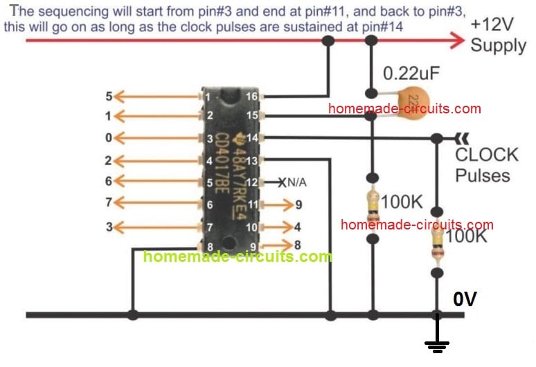
4017 pinout description functioning

Application LED Chaser Circuit using IC 4017 and IC555

The following example GIF circuit shows how the pinouts of a IC 4017 is usually wired with an oscillator for obtaining the sequential logic high outputs. Here the outputs are connected to LEDs for indicating the sequential shift of the logics in response to each clock pulse generated by the IC 555 oscillator at pin#14 of the IC 4017.

You can see that the logic shift happens in response only to the positive clock or positive edge at pin#14 of the IC 4017. The sequence does not respond to the negative pulses or clocks.

IC 4017 Working Simulation
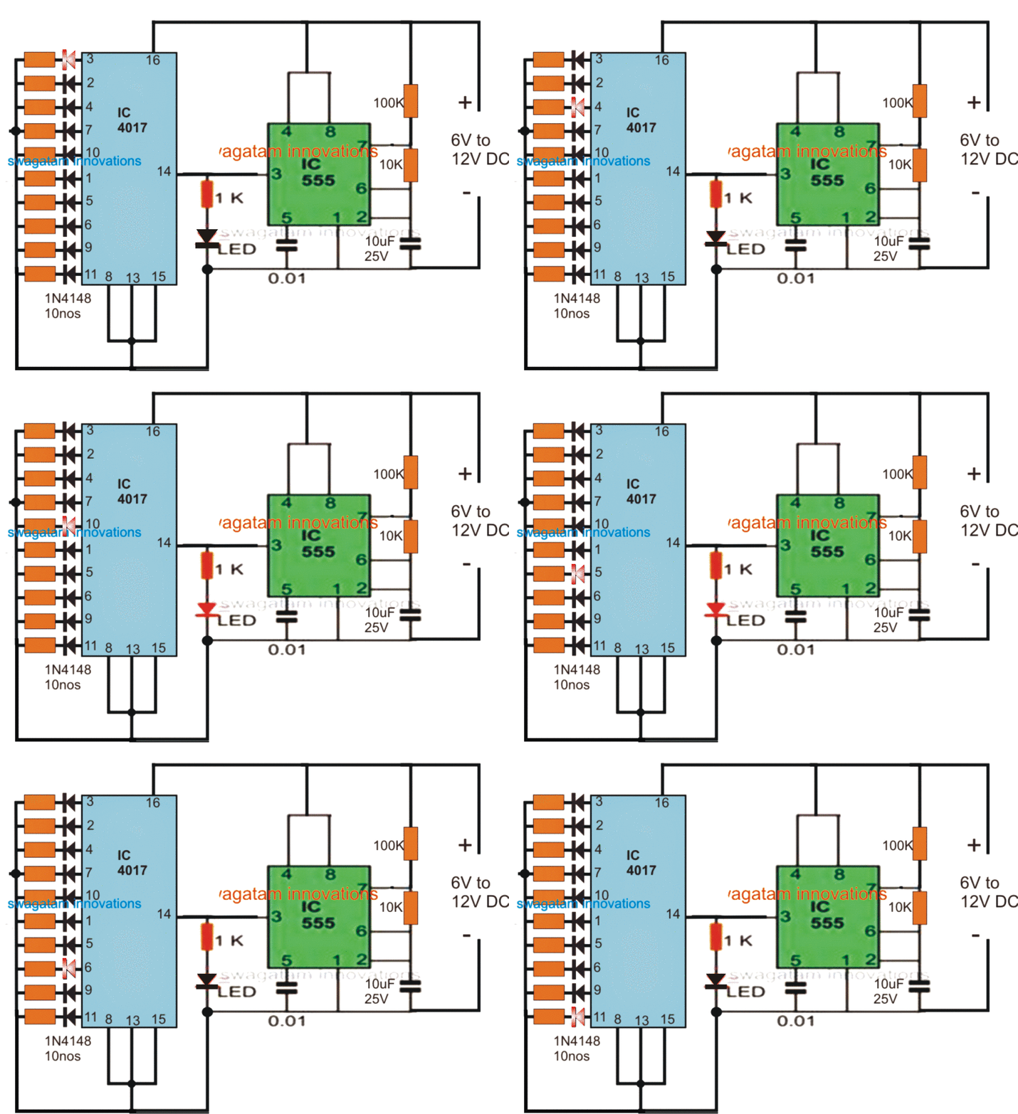
IC 4017 Pinouts working simulation

Video Clip:

How to Cascade Two 4017 ICs for Getting 17 Sequencing Outputs
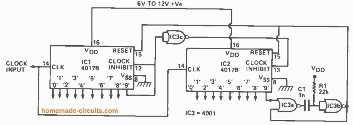
The diagram above shows how to connect two 4017s together to create a 10-to 17 stage counter/decoder. It shows how to cascade two 4017 ICs to get 17 sequencing outputs instead of only 10 from a single IC.  The circuit is shown configured to divide by 17.

The clock signal is supplied in parallel to IC1 and IC2. As soon as  the count falls below 9, the '9' output of IC1 turns low, causing the clock inhibit pin of IC2 to be set high through IC3c, preventing IC2 from being impacted by the clock signals.

The '9' output of IC1 rises high when the 9th clock pulse comes, inhibiting IC1 from further clocking action, while simultaneously driving the clock inhibit terminal of IC2 low through IC2c, allowing IC2 to respond to further clock signals.

When the 17th clock pulse arrives, the '9' output of IC2 swings high for a brief period, triggering the IC3a -IC3b 15uS monostable. This 15us pulse resets both counters to the empty or '0' states.

After that, the counting sequence starts again by itself. Because the '9' output of IC1 and the '0' and '9' outputs of IC2 are "lost" in the counting process, the circuit only has 17 counter/decoder stages available. By connecting the "free" input pin of IC2a to the matching output pin of IC2, the circuit can be made to count by any number between 10 and 17.

How to Cascade Three IC 4017 for Getting 25 Sequencing Outputs
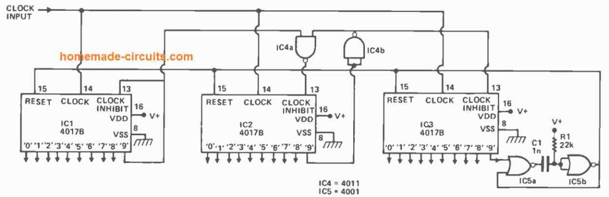
The configuration for creating an 18 to 25 stage counter/decoder from three 4017s can be seen in the diagram above. IC3 is inhibited by IC4b and IC2's low output '9,' whereas IC2 is inhibited by IC4a and IC1's low output '9,' until the 9th clock pulse. Between the 10th and 17th clock pulses, IC1 is inhibited by its high '9' output, while IC3 is inhibited by IC4b and IC2's low output '9'.

Subsequently, between the 18th and 25th clock pulses, IC1 is inhibited by its high '9' output, and IC2 is inhibited through the high '9' outputs of IC1 and IC2 using IC4c, and the whole circuit is reset to the '0' state by means of the IC5a and IC5b monostable.

How to Cascade Four IC 4017 to get 33 Sequencing Outputs
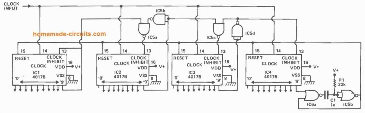
Using a divide-by-33 operation, the above setup shows how to make a 26 to 33 stage counter/decoder set. By interposing extra IC2-1C5a-1C5b stages between 1C2 and 1C3, this design may be extended to provide a ny number of decoded output stages. Each subsequent 40178 stage adds eight decoded outputs to the system.

Sources

  • ti.com
  • st.com
  • electronics.stackexchange.com

You'll also like:

  • function of ICapacitor Inductor Calculations
  • checking DC level of VbeHow to Troubleshoot Transistor (BJT) Circuits Correctly
  • common collectorTransistor Common Collector
  • betaWhat is beta (β) in BJTs

Filed Under: Electronics Theory Tagged With: 4017, Pinouts, Understand

About Swagatam

I am an electronics engineer and doing practical hands-on work from more than 15 years now. Building real circuits, testing them and also making PCB layouts by myself. I really love doing all these things like inventing something new, designing electronics and also helping other people like hobby guys who want to make their own cool circuits at home.

And that is the main reason why I started this website homemade-circuits.com, to share different types of circuit ideas..

If you are having any kind of doubt or question related to circuits then just write down your question in the comment box below, I am like always checking, so I guarantee I will reply you for sure!


Previous Post: « Build Simple Transistor Circuits
Next Post: IC 4060 Pinouts Explained »

Reader Interactions

Questions & Answers

Total Posts: 246
Newest Oldest
LUIS ALVARADO ATENCIO
February 8, 2026 • 6 months ago #200733

disculpen la molestia , pero lo que deseo saber es que tipo de circuitos integrados son los que aparecen en el diagrama: IC3a, IC3b, IC3c, IC4a, IC4b, IC5a, IC5b POR EJMPLO

Reply
SwagatamAdmin
February 9, 2026 • 6 months ago #200755

The IC numbers are given in the diagram, IC 4001 and IC 4011…

Reply
LUIS ALVARADO ATENCIO
February 7, 2026 • 6 months ago #200653

buen dia
En los diagramas mostrados aparecen los circuitos IC1, IC2, IC3, IC4 E IC5. Quiero saber que tipo de circuitos so esos (555, otro?) Y COMO ES SU CONEXXION

Reply
SwagatamAdmin
February 8, 2026 • 6 months ago #200691

555 IC is used as an oscillator IC to feed the clock signals, or the ON/OFF alternate pulses to pin14 of the 4017 ICs.

Reply
hank malach
December 14, 2025 • 8 months ago #195647

hi, my name is hank, my question is the 18 to 25 count circuit schematic at the top is connected for the divide by 18 or is it 25… I need a system that give me a 1 output only every 18 pulses ….which pin of the cd4017 do I need to use….12-13-25 @ 4:AM thank you hank…..

Reply
SwagatamAdmin
December 14, 2025 • 8 months ago #195662

Hi Hank, that circuit is divide by 25 circuit…
Please go on counting from 1st to the last pin of IC1, IC2, IC3, to get the 12, 13, 25 outputs serially.

Reply
Faith Elaine.
September 7, 2025 • 11 months ago #184770

I have built many fine circuits with your advice; I just did one as an LED driver for mini-Christmas lights on a dollhouse. I was thinking about adding a small capacitor to each of the 4 outputs I am using to act as a delay bleed down to the gate of the 2222 transistors I am driving. I am thinking this will give me a more incandescent look to the lights as they switch off.

My question is will this cause any issues with the chip if I do not first install a diode on each output before the cap?

Reply
SwagatamAdmin
September 8, 2025 • 11 months ago #184833

Sounds great! Yes, adding a slight delay will certainly give the LEDs an incandescent filament bulb type of lagging ON/OFF switching appearance.

Reply
Babu
July 5, 2025 • 1 year ago #184171

nice one. thanks. but in my circuit, for the first counts 3, 2,and 4 also, the pin 12 is high. seems they must be low . i have let the pin12 floating as i do not use it in my applicaiton. also, after 3 counts, i want to reset the IC to restart from pin3 onwards. but it is not happening. can you help me.

Reply
Siyamak
October 17, 2025 • 10 months ago #188444

Greetings, dear friend, probably the base connection of an ic555 is not connected to the negative

Reply
SwagatamAdmin
July 5, 2025 • 1 year ago #184172

Thanks Babu, that is correct, pin#12 will be high for the first 3 counts and then become low until pin#9, then again high until pin#4. You can keep it floating or open if you don’t need it.
If you want to reset the IC after pin#4, then just connect the pin#15 with pin#7.
To make sure the IC starts always from pin#3 during power ON, make sure to connect the above mentioned pin#15 with pin#7 through a 10k resistor, and then connect pin#15 with positive rail through a 0.1uF capacitor.

Reply
Rajib Banerjee
March 7, 2025 • 1 year ago #168960

hi, Swagatam its long time follower of you, Need Led Chaser for making aerrow of 10 sets of coloured 5mm led x 2 set for both side. The Led arrange sequence in no. 1-3-3-3-3-3-3-3-3-3 which is same in another side. Lighting Sequence needed blinking start from right and End in 1 and after that total set glowing at a time for 20 sec and again the sequence repeat. Can it be possible in 12 volt 1-2 amp max besic smps driver because it used in road and housing would be 32 mm or maz 40 mm waste pipe housing. Again Besic 4017 and 555 IC Circuit can Perform this. Basically I need this With Showing your regular cheap circuit. Thank You. Waiting For Your Circuit review with Components and Diagram by which I Can make It. Waiting for your convenient.

Reply
SwagatamAdmin
March 7, 2025 • 1 year ago #168970

Thank you Rajib,
So you want the chasing effect on the LED string by initially flashing of the single LED then remaining groups of 3 LEDs chasing forward? Do you want the 3 LED groups to shut off after each 3 LED lights up, or to hold the illumination until the whole array lights up and then shut off together?
If you want them to hold until the whole string is lit up, then you may want to do something as explained in the following article:
https://www.homemade-circuits.com/welcome-chasing-led-display-circuit/
Let me know your opinion….

Reply
Nelio Abreu
March 4, 2025 • 1 year ago #168761

Hi Swagatam,
In cascading, why can’t I cascade the chips directly as shown in this website
how to cascaade 4017 ICs
Using the CarryOut pin?
Thanks.

Reply
SwagatamAdmin
March 4, 2025 • 1 year ago #168763

Hi Nelio,
The pin#12 of the IC 4017 is HIGH for 5 clock pulses and LOW for the next 5 clock pulses in one complete cycle of 10 counts.
So I don’t know how this cascading can cause a continuous sequential flow across the outputs of the two ICs to generate 20 continuous output sequences. If that would be so simple then i wouldn’t have used such complex methods to cascade the 4017 ICs.
But I could be wrong, so I would request you to try this method and let us know if that works or not?

Reply
Nelio Abreu
March 7, 2025 • 1 year ago #168923

Hi, Swagatam,

I have assembled the circuit Cascade with 3 chips 4017, making the stop at Output 3 of the 3rd 4017, since I’m only lighting 20 LED’s, but I have a situation: LEDs connected to Output 0 of 2nd 4017 and Output 0 of 3rd 4017 are always ON, turning OFF when the sequence passes through them, but lighting ON again when reset occurs.
How can I solve this?
Nélio

Reply
SwagatamAdmin
March 7, 2025 • 1 year ago #168938

Hi Nelio,
Did you modify the IC5a input which is connected to pin#9 of IC3 4017? You might need to connect it to pin#4 of IC3 4017?
But I think these circuits are overkill, they can be much simplified using BJTs.

Reply
Nelio Abreu
March 7, 2025 • 1 year ago #168954

Hi, Swagatam,
Has I mentioned, «making the stop at Output 3 of the 3rd 4017» Output 3 which is pin 4 of the 3rd 4017 is connected to the input of IC5a.
I have reviewed the connections several times, but the LED’s connected at Output 0 (pin #3) of 2nd and 3rd 4017 are always ON, turning OFF when the sequence passes by them, but turning back ON when resets occur.

Reply
SwagatamAdmin
March 7, 2025 • 1 year ago #168964

Hi Nelio,
Yes, pin#3 is always ON by default whenever the IC 4017 is in the “standby” position.
So, while your 1st 4017 is operating the other two are “waiting” and in the standby position, which means its pn#3 will be ON.
The easiest way to eliminate this is simply not use the pin#3 of the 2nd and the 3rd ICs.
Or the other method is to power ON the subsequent ICs only when the previous IC has finished counting upto 10. In this way if the ICs have no power in the standby mode, their pin#3 will be off.
If you want this method, I can draw it for you…

Reply
Nelio Abreu
March 7, 2025 • 1 year ago #168966

I’ll probably try another approach…. will test the cascade configuration of the datasheet of the 4017, using a single AND chip.
Thanks anyway.
Nélio.

Reply
SwagatamAdmin
March 7, 2025 • 1 year ago #168972

Ok, great! let me know how it goes…

Reply
Nelio Abreu
March 6, 2025 • 1 year ago #168911

Hi, Swagatam,

The cascade works but not in full sequence.
As soon as the 1st 4017 reaches Output 9, the next 4017 advances from Output 0 to Output 1, and the 1st 4017 resets.

The second 4017 only advances whenever the first 4017 reaches Output 9

Reply
SwagatamAdmin
March 7, 2025 • 1 year ago #168936

Thank you Nelio,
So the results are not correct, and that cascading is not effective.

Reply
Michael R
October 8, 2024 • 2 years ago #162921

Hi Swagatam,
I cannot get a simple 4017 5 LED chaser to work. Have checked and checked and still cannot see what is wrong. All LEDs flash together and sometimes change but not in the expected order. Same problem I had with previous 4017s but have replaced witha brand new one today and see the same problem. Any ideas what may be causing this? I have pin#1 connected to pin#15 to only cycle the first five outputs. Also have input from 555 to pin 14 with 100K ohms pin #14 to ground…
Do I need to put 1K from the unused pins to ground?
Thanks for any help.
Cheers

Reply
SwagatamAdmin
October 8, 2024 • 2 years ago #162928

Hi Michael,
You just need the following basic setup, please try it with a push button first and check whether the output logic sequences or not in response t each pressing of the push button:
4017 test set up
Please keep a pause of at least 2 seconds between each pressing.
If it works then your IC is good, and now you can remove only the 1uF capacitor and keep everything else as is, and integrate the 555 oscillator’s pin#3 with pin#14 of the 4017

Reply
Michael R
October 9, 2024 • 2 years ago #162988

Hi Swagatam,
This has been a work in progress for a little while but now that I have a handle on the 4017 circuit I need to incorporate it into a circuit you provided called “motor-control-using-photo-interruptor”. You may recall it was triggered by a flash/pulse and was to run for only a few revolutions.
I can send the image you linked if you cannot locate it. I actually need to trigger the 4017 circuit simultaneously with the pulse that starts the motor and stop the motor after the number of revolutions counted by the 4017 circuit (this is done by a microswitch on a cam driven by the motor. Each rev will increment the counter like in the push button option you sent earlier). So I need to also add a switch which will replicate the pushbutton and after 5 revs turns off the power to the circuit. Does this make sense?

Reply
SwagatamAdmin
October 9, 2024 • 2 years ago #162990

Hi Michael,
Yes I remember it, and it make sense, however when do you want the 4017 outputs to advance, is it when the light of the photo interrupter is just blocked or after it is just released?
Let me know about it, I will try to figure it out.

Reply
Michael R
October 13, 2024 • 2 years ago #163320

Hi Swagatam
I am removing the photointerrupter and replacing it with a microswitch – closed when pushed otherwise open – so it will be the switch circuit that inputs to pin14 on the 4017IC.
Thanks

Reply
SwagatamAdmin
October 14, 2024 • 2 years ago #163369

Thank you Michael,
So after 5 revs you want the power supply to the 4017 IC circuit should be shut off automatically and permanently, which can be reset back manually through a separate push button maybe, is that right?

Reply
Michael R
October 14, 2024 • 2 years ago #163381

Hi Swagatam.
So after 5 revs when the microswitch is closed by the cam on the motor, the power to the motor should go off until another starting pulse is sent to the main circuit. At 5 revs as I understand it, the 4017 should already be reset so the next time the motor starts it will be at the start of rev 1.
Hope this helps

Reply
SwagatamAdmin
October 14, 2024 • 2 years ago #163387

Ok, understood, so it looks pretty easy actually.
We simply drive the motor through a PNP Darlington transistor whose base is controlled by the 5th output from the 4017 IC.
As soon as this 5th output becomes high, the PNP driver transistor is turned OFF, which turns off the motor.

Reply
Michael R
October 18, 2024 • 2 years ago #163680

Hi Swagatam,
Thanks for the new circuit design. It makes sense. I will look into the reed switches a little more – seems they may have an issue with longevity though?
Problem – I have breadboarded the circuit you sent and have sent 7 ICs and a few PNPs to the graveyard. I am using a 12V power source but would think they should handle it. I do need the 12v for the motor to run.

Reply
Michael R
November 15, 2024 • 2 years ago #165448

Hi Swagatam,
Still persisting with this. Have fried numerous 4017s I will send you the full circuit schematic once I get it finalised and perhaps you can why its popping my ICs. In the whole circuit its only the 4017 that cant handle it. Can I send the KiCad file or do I just send a image? What is the best email for this?

Reply
SwagatamAdmin
November 15, 2024 • 2 years ago #165456

Hi Michael, you can send the image of the schematic too my email, I will check it out and continue the discussion under this comment…
homemadecircuits
@gmail.com

Reply
SwagatamAdmin
October 19, 2024 • 2 years ago #163698

Hi Michael,
The circuit which I provided you is perfect and 100% correct.
12V is the correct and preferable supply DC for any CMOS IC, I hope you are using a CMOS version of the 4017 IC, otherwise it could instantly burn.
The transistor can burn if it is not rated as per the motor current.
Since you said your motor was very small, i assumed that BD140 would be enough for it, nevertheless you can upgrade the transistor to TIP127 for better safety, if required.
Let me know if you happen to troubleshoot the issue…

Reply
Michael R
October 18, 2024 • 2 years ago #163665

Its just a small motor. Testing so far indicates there is virtually no inertia once the power goes off. In fact I am thinking I will need a small capacitor to actually push it past the microswitch. Well fingers crossed anyway 🙂

Reply
SwagatamAdmin
October 18, 2024 • 2 years ago #163671

In that case you can try replacing the microswitch with a reed switch for a frictionless operation.
The following diagram should do the job:
4017 motor control circuit

Reply
Michael R
October 18, 2024 • 2 years ago #163650

Ahh good. Forgot the reset will happen at the same time pin1 goes high. The “looping” circuit is also basically triggered by the starting pulse for the motor. So I need the following circuits to work together (a small challenge for you … well maybe not) :-
a) a circuit that has slow fading/glowing LEDs which are on/off with main power source so this happens regardless of any pulse to the circuit (I have this already)
b) a pulse initiated circuit to power the motor which is only active while pin3 on the 4017IC is low (will this control the start of the motor if the initial pulse is also sent to pin14?)
c) a pulse initiated circuit to count 5 revs (each count is manually triggered by a cam on the motor closing a microswitch at zero degrees rotation)
d) a flashing LED circuit that only has power while the motor is rotating (I have this already).

Does this all make sense and can they work together?
Thanks again for your efforts with this project.

Reply
SwagatamAdmin
October 18, 2024 • 2 years ago #163657

All the above things can be designed, but I am wondering how would you stop the motor rotational inertia. Even if the motor supply is turned off at pin#3, the motor shaft may keep rotating due to inertia and keep triggering the microswitch and never turn off?

Reply
Michael R
October 17, 2024 • 2 years ago #163599

Does that mean there will be only 4 revs? Do the pin assignments need to be advanced by 1?

Reply
SwagatamAdmin
October 18, 2024 • 2 years ago #163635

It will be 5 revs:
3 to 2 = 1 rev
2 to 4 = 2 rev
4 to 7 = 3 rev
7 to 10 = 4 rev
10 to 1 and reset to 3 = 5 rev

Reply
Michael R
October 14, 2024 • 2 years ago #163401

So I assume then that because 4017 pin1 then goes low, the next pulse will be able to start the motor again for 5 revolutions. Correct?

Reply
SwagatamAdmin
October 14, 2024 • 2 years ago #163414

Oh, I forgot that at the 5th pulse at pin#14, the 4017 needs to reset also, which means the PNP transistor would switch OFF only momentarily and then turn ON again instantly.
OK, so we can do one thing, instead of pin#1 we can use the pin#3 with the PNP base to shut off the motor, and let pin#1 be solely for the resetting purpose, connected with pin#15.
This should take care of everything perfectly.

Reply
Michael R
October 8, 2024 • 2 years ago #162932

Sorry. Was using a 10uF capacitor. 1uF works for each push to advance. I will try converting to the 555 input and let you know.

Reply
SwagatamAdmin
October 8, 2024 • 2 years ago #162938

Ok no problem, just make sure to remove the 1uF after you connect the pin#3 of 555 with pin#14 of the 4017.

Reply
Michael R
October 9, 2024 • 2 years ago #162971

Hi Swagatam,
Actually interesting thing now but I think I have worked out what has been happening…
When I remove the capacitor all the LEDs start flashing in sync with the input at pin14. So same problem returns. Capacitor back in and it works nicely.
My 555 circuit has been adjusted to a 50/50 duty cycle so I am guessing that this has been the reason for the strange behaviors I have been seeing. Must be related to how the 4017 handles the pin14 input.

Reply
SwagatamAdmin
October 9, 2024 • 2 years ago #162984

Thanks Michael, for the updates,

CMOS ICs can be specifically sensitive to RF noise and disturbances, the pin#14 being a sensitive input of the IC might be getting rattled by some sort of RF noise existing in your setup, it is not due to 555 IC’s 50/50 duty cycle.
Anyway, glad the problem is solved now through a capacitor.

Reply
Michael R
October 8, 2024 • 2 years ago #162931

Thanks for the quick reply. No luck. I added the push button. The circuit starts with pin3 on but nothing happens when I press the button. But all the LEDs have stopped flashing when the button is pressed (=output from 555).

Reply
Michael R
September 24, 2024 • 2 years ago #161451

Hi Swagatam,
I have built the above circuit from the LED Chaser simulation GIF. Checked and checked but my LEDs do not really chase. They flash randomly with the clock signal from the IC555. I have even swapped the IC4017 to be sure. I have pin1 connected to pin15 as I am only using 5 LEDs connected to pins 3,2,4,7 and 10. I have diodes between the LED cathode and ground. Any ideas as to why they are flashing and not chasing?

Reply
Michael R
September 24, 2024 • 2 years ago #161532

Hi again
Just wondering about the 555 LED. Should it be more OFF and flash ON, or mostly ON and blink OFF (which is what it’s doing now).
Thanks

Reply
SwagatamAdmin
September 25, 2024 • 2 years ago #161609

Hi,
the ON/OFF time is not critical because the 4017 pin#14 will respond and trigger only to the switch-ON rising edge of each pulse…

Reply
SwagatamAdmin
September 24, 2024 • 2 years ago #161470

Hi Michael,
Is the LED at pin#3 of IC 555 flashing correctly, as per the following diagram which you built?
hnet.com gifmaker 2
Your pin#15 connection with pun#1 is correct, and this should allow the 5 LEDs through pin#3,2,4,7,10 to sequence.
Diodes between LED cathode and ground are not required, instead you must resistors.
The above circuit connections are perfect and should enable your 5 LEDs to sequences as intended, please check your circuit again and let me know.

Reply
Michael R
September 24, 2024 • 2 years ago #161487

Actually the 555 LED may be wrong. It is blinking …. not flashing. So, it is ON when power starts and then blinks OFF about every second (10 blinks over 7-8 seconds). The setup for the 555 seems ok though. Have checked it against the sample circuit again.
Thanks

Reply
SwagatamAdmin
September 24, 2024 • 2 years ago #161493

10 blinks per 8 seconds is nothing bad, it looks fine to me.
I think something may be wrong with your 4017 IC, I hope you have correctly connected pin#8 and 13 of IC 4017 with ground.
Also please make sure the voltage input is strictly between 5 and 12V DC.
You can also try adjusting the IC 555 10k resistor to tweak the PWM of the input pulse fed across the pin#14 of the 4017 IC.

Reply
Michael R
September 24, 2024 • 2 years ago #161484

Hi Swagatam,
Thanks for getting back so quickly. The 555 LED is flashing correctly and consistently.
What resistance should be used normally? And how should this ususally be determined?
Thanks
Michael

Reply
SwagatamAdmin
September 24, 2024 • 2 years ago #161495

Thanks Michael,
If your 555 is blinking correctly, then the 4017 output must also sequence accordingly and correctly.
To calculate and set the output flashing rate of the IC 555 you can use any online “555 astable calculator software”
Let me know if you have any further issues…

Reply
Norman D Kelley
July 21, 2024 • 2 years ago #155579

Thanks, Swagatam! The 1 uF cap and 100 ohm resister in series with the output from the CD4017 to the transistor base worked perfectly. This allows the 555 one shot to work properly. Thanks again for your help!

Reply
SwagatamAdmin
July 21, 2024 • 2 years ago #155586

That sounds great, Norman! Glad it worked, and thanks for updating the info!

Reply
Norman D Kelley
July 20, 2024 • 2 years ago #155419

Hi Swagatam,
I think I have found a way around the problem. While testing, I found that the FLM038A can be triggered with a +voltage pulse without a transistor. Therefor I split the TTP223 touch module output with two 10K resistors. One of the split signals is used to trigger the advancement and play of the FLM038A and the other split is used to trigger pin 14 of the cd4017. Each time the touch switch is touched, the 4017 advances with nothing connected to its outputs except pin 11. Pin 11 drives a transistor through a 10K resistor that grounds pin 2 of a 555 one shot. The 555 one shot output drives a transistor to ground the Piezo Siren. Works on the breadboard, so I am now going to build it. I still would like to know if there is a way to produce a short pulse from the outputs of the 4017 for future reference. Thanks!

Reply
SwagatamAdmin
July 20, 2024 • 2 years ago #155421

Thanks for updating the info Norman, Glad it is solved now.
I have replied to your earlier comment regarding how to use 4017 with a short pulsed output, please check the comment reply.

Reply
Norman D Kelley
July 20, 2024 • 2 years ago #155394

Hi Swagatam,
Is there any way to convert the outputs from a 4017 to a single short pulse instead of a continuous signal? If not, what about another IC such as a 74164 or a 74595? Thanks!

Reply
SwagatamAdmin
July 20, 2024 • 2 years ago #155415

Hi Norman, yes that’s a good idea.
You can implement this simply by adding a 1uF capacitor and a 100 ohm resistor in series between the 4017 output and the transistor base.
The 1N4148 must be removed in this situation.
Try to make the capacitor value smaller, as far as possible.

Reply
Norman D Kelley
July 20, 2024 • 2 years ago #155388

The zeners are not working. I tried using a single transistor and two transistors and two reed ralays. None of them works. The only way it works is if I skip every other 4017 output.

Reply
Norman D Kelley
July 19, 2024 • 2 years ago #155341

The system runs off of 5v. Should the zeners be forward or backward? The black bar away from the 4148 or toward the 4148. I tried it with a 3,3v zener since the circuit runs on 5v.

Reply
SwagatamAdmin
July 19, 2024 • 2 years ago #155344

For 5V, you can try 3.3V zener diodes.
The black bar of the zener diode should meet the black bar of the 1N4148 diode.

Reply
Norman D Kelley
July 19, 2024 • 2 years ago #155318

Hi Swagatam,
I am working on a CD4017 circuit and need some help. The circuit uses a TTP223 touch module to advance the 4017 through its 10 outputs. All 4017 outputs are equipped with 1N4148 protection diodes. Outputs 3 2 4 7 10 1 5 6 9 all trigger a BC547 to trigger a FLM038A doorbell module. Each time the FLM038A is triggered, it advances and plays a different sound or melody. Output 11 of the 4017 is used to trigger a 555 one shot that triggers a piezo siren circuit. I have found that I have to skip outputs 2 7 1 6 11 because the BC547 is continuously triggered if all 4017 outputs are connected. I tried using two separate output rails with two separate transistors. That doesn’t work either. Only one of the output rails triggers the FLM038A. Both the transistors are parallel connected to the FLM038A pins. Could you please suggest a remedy for my problem. I can email a circuit schematic if you need that. Thanks!

Reply
SwagatamAdmin
July 19, 2024 • 2 years ago #155319

Hi Norman,
It is happening because there’s no deadtime between the 4017 IC outputs, which means the transition between the two outputs is seamless without any breaks.
To induce a deadtime you can try adding a 6V or 9V zener diode in series with the 1N4148 diodes and check if that helps to break the transition between the pinouts?
Let me know how it goes?

Reply
Johnny
June 11, 2023 • 3 years ago #143350

Good explaination how a 4017 ic works

Reply
Yeboyeah
May 4, 2023 • 3 years ago #142256

Hi Swagatam, is it possible to use the 4017 as a one shot counter and at the end of the sequence the pin to remain “High”
I have found your site to be very interesting.
Thank you

Reply
SwagatamAdmin
May 5, 2023 • 3 years ago #142262

Thank you Yeboyeah, 4017 cannot be used as a one shot counter. To make this happen you will need an additional 555 astable or an oscillator circuit with a push button latching facility.

Reply
Yeboyeah
May 5, 2023 • 3 years ago #142270

Thank you for your prompt reply, much appreciated.

Would I not need a 555 as a monostable, triggered from the last output of the 4017?

Thank you

Reply
SwagatamAdmin
May 5, 2023 • 3 years ago #142273

The 4017 requires a pulsed input at its pin#14 so an astable would be required to supply the pulses to the 4017 pin#14 in order to create a sequential output from the 4017 outputs.
The last output pin which is pin#11 can be latched or freezed by connecting it with the pin13 of the IC.

Reply
StoneLion
March 27, 2023 • 3 years ago #141435

Hi I learned about the 4017b as a kid a number of years ago and I think this is the clearest description maybe of any cmos circuit I have ever read so thank you for sharing it in such plain language, it’s been a huge help for beginners in this really awesome line of cmos ic’s.
I have a project/idea I’m working on and I’d like to drive relays or perhaps transistors or I suppose both may be needed for using the 4017’s outputs to switch various audio line level signals. At 20mA I don’t think there is a relay that would function at such low current, my guess is that it would starve the circuit or worse so I wanted to ask your opinion on how I should go about it. My idea was outputs to bases of transistors which would switch by collectors to relay coils but there may be a smarter way to accomplish this ? I’m pretty new to transistors so any help would be hugely appreciated. Again thanks so much.

Reply
SwagatamAdmin
March 28, 2023 • 3 years ago #141447

Thank you Stonelion, I am glad you found the post useful.
Yes transistor relay drivers is the common method for switching a load across a 4017 outputs, however if your load current is small then tiny relays can be employed. These relays are typically rated at 10 mA so these can be directly connected with the outputs of the 4017 IC.

Reply
Arjen
January 5, 2023 • 4 years ago #138614

Hi,
Great explanation of this IC.
But I am a bit of a newbee and the 4017 doesn’t want to do what I tell it to.
Here’s is what I did.
I connected 8 and 15 to negative of a CR2032 cell. 16 to the positive.
Then 3 to via a LED to negative of another CR2032.
I use 14 to create positive pulses from the last CR2032.
I expect the LED to flash every 10 contacts of 14. But it doesn’t. What am I doing wrong?

I want to use this for my treadmill to create a ANT+ signal via my Garmin bike-sensor.
This sensor has a magnet switch which reacts to the passing of a magnet on a bike-wheel.
Eventually I want this sensor, the magnet switch, to create the pulses for 14.
But, as it seems, I am far away from that point.

Reply
SwagatamAdmin
January 5, 2023 • 4 years ago #138615

Hi, thanks for liking the above post.
Did you connect all the negatives of the CR2032 in common with the negative of the IC?.
Meaning, the negative side of all the cells must join with pin#8, pin#15 and pin#13 of the IC.
Make sure pin#13 is also connected to the ground line.

Reply
Arjen
January 5, 2023 • 4 years ago #138622

Ok, now I have only 1 cr2032 connected.
Negative to 8, 13,15, 3
Positive to 16
I use a wire to 14 to connect pulses to CR2032 positive.
On 3 there is a LED connected so I can see the result of my pulses.
I also had a LED connected to 1 to see if the counting works.
Most of the times the lights start blinking fast without needing a pulse.
After about 5 seconds they stop blinking..
Just one time the LEDs reacted to my pulses.
I can’t replicate it. So i must be doing something wrong.

Reply
SwagatamAdmin
January 6, 2023 • 4 years ago #138634

3V is the minimum limit of the IC 4017, and anything under 3V will cause the IC to work abnormally.

So I would recommend you to use a proper 5 V or 12V supply for testing your circuit.

If you are using a CR2032, you can use two of them in series to make the supply above 5 V.

Reply
Arjen
January 6, 2023 • 4 years ago #138645

Thanks for all your help but I am about to give up.
I tried 3V, 6V, 9V (3 CR2032 in series).
The blinking has stopped but it seems to count at random.
I tried another 4017BE with the same results, I tried Q0 for another count sequence.

The LED blinks at contact. When pulsing sometimes it stays on until the next pulse, fully shining, somethings it is shining just a little, sometimes a flash. The count is really not consistent. It may be 4 or 7 or 11.
The only thing my setup differs from your scheme is the capacitor. I don’t have one at hand so I can not solder that in.
I am running out of options.

Reply
SwagatamAdmin
January 6, 2023 • 4 years ago #138651

4017 IC is a very straightforward IC and should start responding correctly immediately without faltering, I am not sure why you are having problems with this simple procedure?

I think your positive clocks at pin#14 is not proper. Try connecting a 1uF capacitor or some other value capacitor between pin#14 and ground, and I hope you already have a resistor between pin#14 and ground. So a capacitor and a resistor across pin#14 and ground should ensure proper clocking of pin#14 and proper sequencing across the output pinouts.

The above capacitor very crucial.

Reply
Ed Findysz
December 9, 2022 • 4 years ago #137122

Hello Swagatam,
I apricate your explanation of the 4017 IC. I have created a wire continuity checker using the the 555 and 4017 . The 4017 outputs drive a LM358 circuit that checks installed wires at 1 ohm or less. Currently I send Pin 11 (output 9) to Pin 15 to reset the counter. My issue is that I will be using this tester to for multiple combinations of cables with several of them under 9 wires. So I would like to find a way for the counter to go back to Pin 3 with less than 9 wires. Is there a way through dip switches or something else to make it reset based on a variable number of inputs? Thank You.

Reply
SwagatamAdmin
December 10, 2022 • 4 years ago #137159

Thank you Ed, you can probably use a rotary switch to select and set the desired reset output from the IC. The following images provide more information regarding the subject.

rotary switch

Rotary switch 11 position

Reply
Ed Findysz
December 12, 2022 • 4 years ago #137317

Thank you Swagatam for the response. I did find find a schematic using a rotary switch after I emailed you. I think that will work well for my application. However, you added the 1M resistor on the ground side which I did not see on the other schematic. Being a newbie, my assumption is that is used to pull down the voltage on the selected output. That is very helpful to know. Thank you again.

Reply
SwagatamAdmin
December 13, 2022 • 4 years ago #137345

You are welcome Ed!
The 1M is for pi#15, to make sure this pin never stays floating even for a second while the rotary switch is being moved. All inputs of CMOS IC must be terminated to a ground or positive potential as preferred, by default, to ensure proper working of the IC.

Reply
Ed Findysz
December 13, 2022 • 4 years ago #137380

Thank you Swagatam that makes sense. Yesterday I incorporated the switch into the circuits and was testing it only on three of the nine. I was having issues with it working correctly. On the continuity tester circuits, there is an electrolytic capacitor on the power to the LM358. Once I removed them, the switch worked as needed. My guess is that the capacitor was causing pin15 to “float” as you stated.

Reply
SwagatamAdmin
December 14, 2022 • 4 years ago #137403

Thanks for the update Ed, you may be right, however the exact reason could be confirmed only after checking the schematic visually.

Reply
Ed Findysz
December 15, 2022 • 4 years ago #137440

Thank you again Swagatam for all your help. I have the rotary switch in the circuit and fully functional. My last addition to the circuit would be to add a momentary switch to reset the IC on demand. Since the 4017 is being driven by a 555, sometimes after power is turned on it does not start with the first output. This will be used as a cable tester and it may confuse an operator not familiar with how the circuit works if when powered on it does not start at output Q0. So I would include a switch as a manual reset. Thank you.

Reply
SwagatamAdmin
December 15, 2022 • 4 years ago #137452

That’s great Ed! Glad it is working now. For ensuring that the 4017 always starts from the first pinout (pin#3) whenever power is switched ON, you just have to add a capacitor between the positive line and the pin#15. The capacitor can be any small value such as a 0.22uF or 0.47uF etc.
However, for this to work, the 4017 outputs associated with pin#15 must be connected through a high value resistor such as 10K

Reply
Ed Findysz
December 15, 2022 • 4 years ago #137480

Hi Swagatam,
I added a .47 uF as you suggested and it works great. That is a much better option that using a rocker switch. I apricate all your help and education.

Reply
SwagatamAdmin
December 16, 2022 • 4 years ago #137535

Thank you Ed, I’m glad it worked. It is a standard auto resetting method employed in all CMOS ICs which has a reset pin.

Reply
Steve
October 15, 2022 • 4 years ago #133962

Hi, superb explanation! How do I set up to toggle between 2 led’s and all off before resetting?

Reply
SwagatamAdmin
October 15, 2022 • 4 years ago #133963

Thank you and glad you found it useful.

You just have to disconnect pin#15 from the ground and connect it with the pinout which comes just after the last LED pinout.

For example if you want to toggle between two LEDs, you will connect the first LED to pin#3 and second one to pin#2, and then to make sure the sequence keeps returning back to the first LED you will need to connect the pin#15 with pin#4, which comes right after pin#2 (second LED).

Also you have to make sure that the IC always resets and starts with pin#3 whenever the power is initially switched ON.

For this make sure to connect pin#15 with pin#4 through a 10K or 100K resistor, and connect a 1uF capacitor between pin#15 and the positive supply line.

Reply
Steve
October 15, 2022 • 4 years ago #133970

Wow, lightning reply…..Superb! Been trying to find a way to jump between 2 LED’s and OFF with one toggle button. Simple I thought…. Nah, not till I found this site.
Will this touch ic work as a switch signal along with (any) 4017?

Many thanks.

Reply
SwagatamAdmin
October 16, 2022 • 4 years ago #133977

I am glad to help! You do not need any external circuits for the touch activation. It can be simply done using a couple of transistors attached to pin#14 of the 4017 IC.

You can try the second circuit from the following article:

https://www.homemade-circuits.com/simple-touch-sensor-switch-circuit/

Reply
View Older Comments

Need Help? Please Leave a Comment! We value your input—Kindly keep it relevant to the above topic! Cancel reply

Your email address will not be published. Required fields are marked *

Primary Sidebar


Categories

  • Arduino Projects (95)
  • Audio and Amplifier Projects (134)
  • Automation Projects (18)
  • Automobile Electronics (104)
  • Battery Charger Circuits (90)
  • Datasheets and Components (109)
  • Electronics Theory (150)
  • Energy from Magnets and Earth (41)
  • Games and Sports Projects (11)
  • Grid and 3-Phase (20)
  • Health related Projects (27)
  • Home Electrical Circuits (13)
  • Indicator Circuits (16)
  • Inverter Circuits (100)
  • Lamps and Lights (163)
  • Meters and Testers (72)
  • Mini Projects (28)
  • Motor Controller (68)
  • Oscillator Circuits (30)
  • Pets and Pests (15)
  • Power Supply Circuits (91)
  • Remote Control Circuits (50)
  • Security and Alarm (65)
  • Sensors and Detectors (107)
  • SMPS and Converters (46)
  • Solar Controller Circuits (62)
  • Temperature Controllers (44)
  • Timer and Delay Relay (50)
  • Voltage Control and Protection (44)
  • Water Controller (37)
  • Wireless Circuits (31)


Circuit Simulator

circuit simulator image


Subscribe to get New Circuits in your Email


Other Links

  • Privacy Policy
  • Cookie Policy
  • Disclaimer
  • Copyright
  • Videos
  • Sitemap

People also Search

555 Circuits | 741 Circuits | LM324 Circuits | LM338 Circuits | 4017 Circuits | Ultrasonic Projects | SMPS Projects | Christmas Projects | MOSFETs | Radio Circuits | Laser Circuits | PIR Projects |


Recent Comments

  • Swagatam on Simple Delay Timer Circuits Explained
  • Swagatam on SG3525 Full Bridge Inverter Circuit
  • Swagatam on How to Replace a Transistor (BJT) with a MOSFET
  • Swagatam on Inverter Circuit with Feedback Control
  • Ngwabe David on SG3525 Full Bridge Inverter Circuit

Social Profiles

  • Twitter
  • YouTube
  • Instagram
  • Pinterest
  • My Facebook-Page
  • Stack Exchange
  • Linkedin

© 2026 · Swagatam Innovations