The article illustrates a simple yet innovative, fancy car turn signal light circuit which produces a rising bar graph sequence effect when switched ON.
The circuit idea was requested by Mr. +Bruce Lowry. I have explained more.
Technical Specifications
I am after a circuit design similar to the LED Bar Graph circuit that is found on this site/blog.
What I want to develop is a front turn signal sequential flasher that illuminates and holds the lights from top to bottom and then cycles them again and again until the turn signal is turned off.
I need to drive exactly 12 Amber LED's that drop 1.8 volts per LED. The LED's are laid out from top to bottom as such.
- 1 (number of LED's)
- 1(number of LED's)
- 1(number of LED's)
- 2(number of LED's)
- 3(number of LED's)
- 4(number of LED's)
I would like to illuminate the first one at the top and hold and then move on to the second one down and so forth until all 6 rows which consist of 12 total LED's are illuminated and then start the sequence over.
Variable resistors should be included so that the clock frequency can be altered. This will allow me speed up or slow down the illumination and hold of the LED's.
Plus if there is a variance in the driver side circuit and the passenger side I could use the adjustability to "syncronize" the working rates of both sides. (turning on the hazard flashers to observe both sides being enabled and sequencing would be a good way to visually check this)
In the connector to the front turn signals I am working with three connections.
Top pin is 12 volts constant when running lights are turned on (oh, just a thought- It would be nice to use the entire string of LED's as running lights as well) Middle Pin is zero volts (GROUND) and lower pin is 0-12 volts when the turn signal is activated.
I need a working circuit that will handle automotive voltages that are not always 12 volts in practice , but can range up to 14 or so volts in actual real world use.
A complete circuit diagram would be helpful. Including resistor values for driving the different multiples of LED's and if each LED would have its own resistor or just run them in series with one resistor.
Audio/Video Representation
The Design
The above circuit can be built using two different types of circuit configurations. One which uses the IC 4017, and the other through the IC 74LS164. Here we'll discuss the one which uses the IC 4017.
As shown in the first circuit diagram, the entire design is wired around the IC 4017.
We know that the IC 4017 which is a johnsons divide by 10 decade counter/divider chip produces sequencing high logic pulses on its outputs in response to clocks applied on its pin#14.
In response to each high pulse on pin#14, a high logic shifts from one output to the next in the following pin-out order: 3-2-4-7-10-1-5-6-9-11.
Thus all the 10 outputs become high sequentially until the last pin#11 becomes high after which the sequence returns to pin#3 so that the cycle can repeat yet again.
The cycle keeps repeating as long as the clock pulses are sustained at its pin#14.
However the sequencing pattern does not keep the outputs illuminated while shifting. The outputs become high and then become low again as the sequence shifts from one pin out to the other.
It means at any instant only one output is high during the sequencing process.
If we connect 10 LEDs at the above 10 outputs of the IC 4017, it would provide an impression of a single LED chasing effect, however since for the present car turn signal application we want a bar graph kind of appearance we would want the LEDs to stay and hold their illumination as the sequence proceeds from the start to the finish pin-outs.
To implement this "hold" feature we need to introduce a latching feature with the given outputs.
This can be simply done with the use of SCRs, because as per the characteristics SCRs latch their MT1, MT2 leads if the supply is a DC. Therefore it perfectly suits our application.
By connecting SCRs at the first 6 outputs of the IC we can simply implement the bar graph kind of feature such that the LeDs hold and stay illuminated until the complete is completed.
Pin#1 provides the last sequencing output after which the IC should shut down all the LEDs and begin the procedure all over again.
For actuating the above action, the transistor T1 stage in introduced at the next pin#5, which instantly inhibits the supply voltage to the SCrs so that all of them shutdown.
Pin#6 is tied to the reset pin#15 of the IC which makes sure the sequence gets back to pin#3 as soon as the LEDs shut OFF, enabling the next cycle to commence.
Circuit Diagram
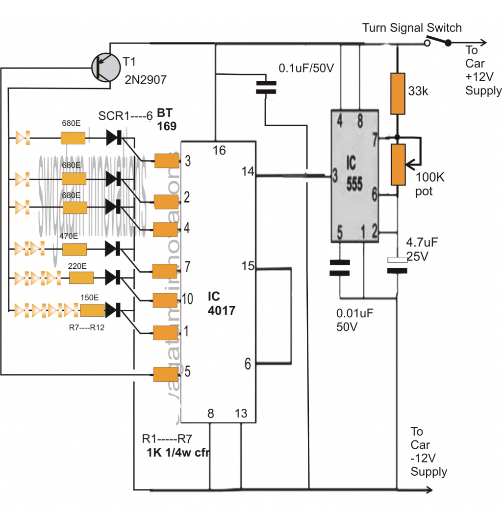
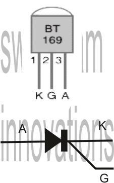
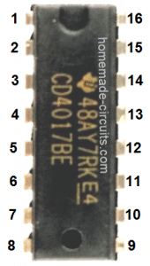
As rightly expressed by Mr. Bruce, the above circuit will not function properly under a fluctuating DC which would be normally available across the existing turn signal light outputs due to switching of the flasher relay.
Adding a Delay Timer
However the above circuit can be simply modified by adding a small time delay circuit, which would hold the current and keep the circuit functioning switched ON by supplying the required amount of power during the absence of supply from the flasher relay.
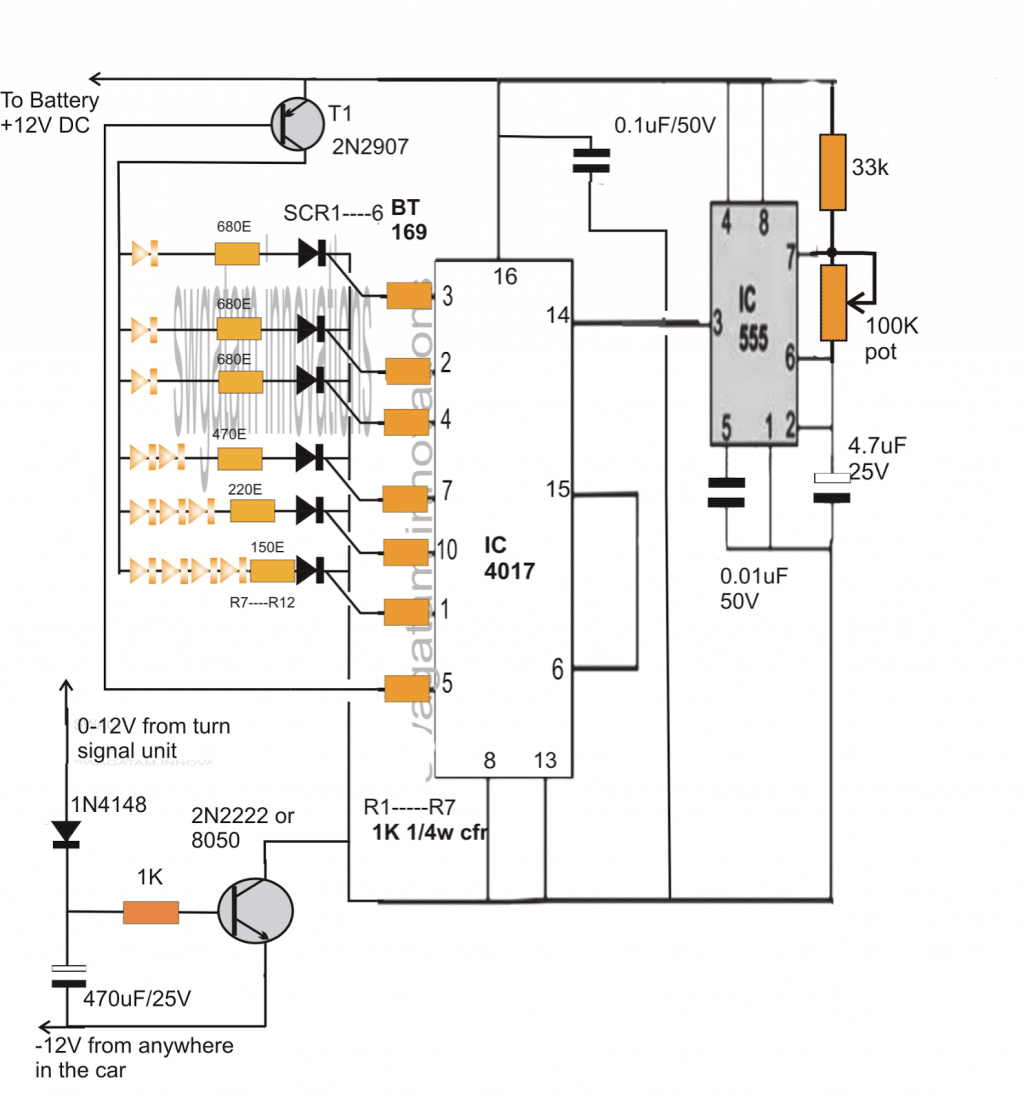
The above sequential car turn signal light circuit was successfully built and tested by Mr.Bruce Lowry.
The wonderful results can be witnessed in the following video. Please refer to the comments to learn regarding the whole process.
With an adjustable rate of flash added, the circuit now looks much enhanced. Courtesy: Mr.Bruce Lowry.
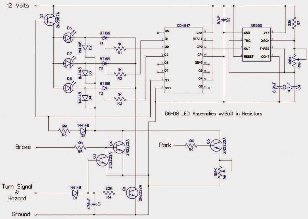
The above design was further modified by Mr. Jason in order to implement additional specific actions such as making the LEDs stay solid when the brakes are applied, but also making sure that the LEDs stayed in the flashing/running mode in case both: the turn signal and the brakes were switched ON together or simultaneously.
Modifying Further
The modified design which is attached below has an additional feature wherein the LEDs could also be used as park lights thereby making the above circuit a 3 in 1 unit:
Here's the complete design drawn by Mr. Jason for your viewing pleasure:


Questions & Answers
Had some PCB's professionally etched for this project. Problem is I did not modify the schematic that I created in CADSoft Eagle before submitting them to the board house. The schematic is just about the same as the one that we were using before building the simple 555 Flasher circuit and integrating it with the 4017 portion of the circuit.
Needless to say I stuffed the board with all the necessary components and it just gives me a solid light on the LED timing indicator light. I have tried to remove some components and add jumpers where necessary , but still no luck. I still have the protoboard version of the circuit working just fine. Can I send you a fully stuffed PCB via the Postal Service and have you take a look at it for me? I would pay shipping and whatever is necessary. I would include the exact schematic that the board was built from as well.
b d zero g @ comcast.net is my email.
Sending it to me would be a long and a complex procedure. I am sure you can do it yourself, try it afresh with a new PCB.
Do it stage-wise. First make the 555 stage and confirm the flashing by connecting an LED at its output.
Next stuff the 4017 stage and initially keep the two stages disconnected, check if the LEDs are getting latched or not. If they are getting latched would mean that either the IC is faulty or the transistor is put the wrong way round or may be faulty….remove the transistor and check again.
You would get to the root in that way. cheers!
Use IC sockets for both the ICs, this will make replacing easier in doubtful cases.
Good thoughts! I will keep at it. I think I will take your advice on all counts! I like the sockets for the IC's idea as that would make swapping new ones in if needed very painless!
I'll post up pictures of the completed board after and "if" I can get it to function properly.
Thanks! wish you the best:)
Well, there is no way that I am going to resolve the issue with the PCB's. Too many connections that are not correct! Went back to square one and built the entire circuit again. This time I built it on a proto board so that I can pull and relocate components much easier than desoldering and resoldering. I am working to get a finalized schematic that I can send to the board house and have them make me a PCB that actually works. So you are probably asking yourself well why not just probe every connection on the board that you soldered up and had working. Well with this many connections and the extent of solder that is on the back of the board it is really not that easy.
I completely redrew the schematic in Eagle by CadSoft. Excellent PCB and board layout tool for those hobbiests out there. I tried 4-5 and Eagle's free version is really one of the best.
OK . So I have built the schematic exactly as shown in this image uploaded to PhotoBucket.
i941.photobucket.com/albums/ad257/e30vert/sequential_update_zps8fbd9de3.png
I confirmed that the trigger LED off of Pin 3 on the 555 timer was indeed triggering and has the adjustable rate that is working.
Problem is my sequence for firing and latching the LED's on the output are not correct.
Here is what they output. When power is applied
YouTube Video= http://www.youtube.com/watch?v=hbBeOpqyAt0&feature=c4-overview&list=UUqoDhEjYuBErc4b8wu16ebg
The bottom LEDs rows 5 and 6 never even come on and they all light up initialy and then turn of one at a time while enabling the one right before it.
I need some more guidance and help. Been going round and round with this.
Wow! that's a lot of handwork, but I am sure it would not go in waste.
I am not able to find pin no.8 of the IC 4017, I am finding it difficult to locate? Are you sure it's connected.
Pin#8 of IC555 is not connected with the ground of IC 4017
C1 polarity is not correct.
These are the few things I noticed quickly, there might be a few more, not sure though.
I think you should have plotted my diagram because it's cent percent correct and much easier to trace.
…pin#16 of IC4017 is also missing.
Look right in the center of the schematic where it says IC2P and then to the left of that is VDD for the 4017 chip. That is Pin #16 and to the right side of IC2P is Pin # 8 of the 4017 chip. Can you please check these for me now that I have indicated where pin 16 and 8 connect?
I will switch the polarity of the C 1 cap for starters.
I am going to make changes to the schematic and repost new schematic every time now as that is how I screwed up before. Building the circuit but NOT tracking and updating the schematic with the changes to the physical circuit.
Here is new circuit with change made (cap) and red circles around pin 16 and pin 8 of the 4017 chip.
As I recall when I connected pin # 8 of the 555 timer to the 4017 chip pin #16 this caused the trigger LED to no longer blink and remain on CONSTANT. I just validated this again and YES it stops the blinking of the trigger LED and makes it a constant on. Not what we want. So no connection there is made currently! Nice to be able to drop a wire in to the circuit and remove in seconds rather than minutes (soldering and desoldering).
It has been alot of hand work, but using a wire plug in protoboard over the solder on board is very helpful for making quick circuit changes!
Flipped cap polarity and same output observed on the LED's. So now it is more correct but has a ways to go still. 🙂
Double checked the pin outputs on the two transistors 2N2222 which is Emitter Base Collector from Left to right and also the 2N2907 which is also Emitter Base Collector starting from the Left moving to right and found that 2N2222 was inverted with Collector being where Emitter should be. Flipped it around and found no difference in the LED outputs! That is super weird. Neither changing the C1 polarity or flipping the 2N2222 had ANY affect?
OK got it!
It means there's something wrong with your 4017 section. You may confirm it manually.
Remove the IC from the socket and then check the 555 LEDresponse, if it flashes means the fault is within the IC 4017.
Replace it with a new one and check again.
Alternatively you can do the following test.
Connect any resistor above 1K across pin14 and ground and trigger this pinout manually by momentarily touching the positive to it. With each touch the output must sequence one step forward across the output pins, as it would do during normal operations.
But before this you must connect the LED common anodes with the collector of 2N2907.
Pulled the 4017 chip and the trigger LED of the 555 portion of the circuit still flashed.
Then replaced the 4017 with another fresh one and plugged in all the previous wiring. Output LEDs are still doing the exact same thing. Then I connected all the LED common anodes to pin 14 on the 4017. Added a 10 K ohm resistor to pin 14 of the 4017 and ground. Then I touched the resistor to positive 12 volts momentarily. It appears to be counting but not right at all.
First touch – all four of the segments lit from top to bottom no lights on the 5th or 6th segment
Second touch -1st second and 4th dimly lit No 3rd or 5th and 6th
Third touch – 2nd 3rd and 4th dimly lit no 1 st or 5th and 6th
Fourth touch – 1st 2nd and fourth dimly lit no third 5th or 6th.
Fifth touch 1 st 3rd and 4th segment dimly lit. No 2nd 5th or 6th
Sixth touch same as first touch …
In the above when I type dimly lit it is for the 4 th set of LEDs only.
All led common anode should be connected to collector of 2907, not to pin14.
the end of 10k which is connected to pin14 should be manually touched with the positive.
I think you should refer to your previous prototype and compare each and every stage with the present one.
I figured out that my connector to the LEDs was inverted so that pin 6 was where pin one should be and vicea versa . I flipped the connector around but it's still not counting right . It's like it lights all the segments up and then turns them off starting from segment six working upward towards one. And when one segment is turned off the previous one below it is turned on. It's gotta be something with the way the SCRs are wired. Or the connections to the 2907 transistor. It's weird that the LEDs should all be off and instead they all turn on at first . It's like an inverted effect of the sequencing .
I think should go back the basic design and gradually make the modifications one by one, this will enable you to distinguish and identify anything that might be incorrect in the course of the actions.
Im on it! Ripped everything out of the ProtoBoard. Decided to measure resistance on all resistors and strangely actually found one that was was lower resistance than it should have been. It was the 160 Ohm and it was nearly a short. I know that would not cause the issues , but Im glad that I caught that.
Ive got the 555 portion of the circuit built and it is outputting the variable blink of the LED so that's great! Im gonna build the other portion (4017) on the complete other 1/2 of the board so each stage is well defined and not so close together.
Hmmm… you are on the right tracks, this is the way I learned all the practical stuffs when I was new in the field…I am sure you would soon figure out the fault.
Built the 4017 stage and it works ! Now I get to redraw the entire schematic and submit to the board house again. Yeah! This time I am triple checking the schematic before I send it in. 🙂
Thanks for the ongoing assistance. The socket idea was helpful and I also picked up some RAD Machine Pin Jumper wires. The ends are these little machined pins with very nice flexible wire. They are made by Twin Industries http://www.twinind.com
Found here http://www.twinind.com/catalog_detail.php?id=410
They make plugging in connections to a Protoboard/Breadboard amazingly simplified.
I have another circuit that I need help on. 🙂
Great going….feel free to present your new request.
Swagatam. I'm posting here per your suggestion. All the info posted between you and Bruce is really helpful. I have ordered all the parts to build this circuit, and then I will need your help to add an (all on at once) solid brake light function that is overridden by the sequential function. Another thing I forgot to mention. Your other circuit with the chasing led's was designed to control both left and right. Can we change this to do the same before I build it or would I be better off to build two? I will have enough parts to do either, so it's fine if it's too much trouble. I would also like to use the IC 4060 in place of the 555 if possible as you mentioned it was much more accurate. Again, not an issue if too much trouble. Thanks for all the help. This is invaluable.
You are welcome Chris!
The two circuits are entirely different with their functions, so it would become too confusing if we tried to include these together at once.
The other design produces ordinary sequencing effect while here the LEDs "hold" and retain their illumination as they sequence.
May be you can outline the requirements yet again here, so that we may be able to figure them out step wise.
I would suggest you make the above circuit first and then we can proceed with the mods.
Yes, 4060 would be a welcome replacement for 555, no issues about it.
Cheers!:)
Sounds great. Several parts came today, but I'm still waiting on a few, so I'll go ahead and post up the requirements.
I want to control 2 led taillights. Each taillight will have 7 segments of led's. 6 segments containing 2 led's and 1 segment containing 4 led's. I want each segment to light up one at a time with each one staying lit until all 7 are lit, and then all segments to turn off and then repeat the process. The 6 segments containing 2 led's each will light up first and the segment with 4 led's will be the last one to light up. This should all be the same as the above circuit except for the number of led's in each segment, and using a 4060 in place of the 555. I will also use the time delay circuit in the second diagram to supply constant current when the flasher turns on and off.
Here's where the modification will come in. I need to add a brake light input that will make all 7 segments on each taillights turn on at one time as long as there is current on the brake light wire. The exception to this rule is, anytime the turn signal is on at the same time as the brake light, I need the turn signal to take priority, and the lights to flash in sequence just as they would if the brake light wire didn't have current.
Got it, that's pretty much the same what I will explained earlier. The modifications would be quite simple, so we can do it once the above primary design is built and confirmed.
Ok. Sorry it took so long. It took a while to get everything and get the circuit board built. I built the above design, and since I have 7 sequences instead of 6, I connected pin 6 of the IC4017 to T1 and pin 9 to pin 16 which follows the output sequence of the 4017. This seems to do what I want, except the capacitor on the turn signal input causes the sequences to continue for a few seconds after the signal is switched off, which I don't want. I think I can use the first diagram above and add a relay for the turn signal input if we can't solve that issue. Also the speed of the sequence seems to vary a lot, and I assume using the IC4060 in place of the 555 would solve that issue since it is more accurate. So now, I need to find out the differences to replace the 555 with the 4060 and how to ad a brake light function where all led's come on at once with a 12v brake light input, but that will not take priority over the turn signal sequence. If there were to be a 12v input on the turn signal and the brake input at the same time, I would need the brake input to be ignored and the turn signal to operate with the 7 step sequence.
Great!
You can try reducing the input cap value to some appropriate level for correcting the issue.
Anyway, here's what you must do for introducing the brake light feature as per your specs:
Take some 1N4148 diodes and connect each of their anodes separately to each of the SCR anodes.
Join the cathodes of these diodes to make a common termination.
Join this termination to the collector of a BC547 transistor, let's call it Q1. The emitter of Q1 goes to the ground while the base links with the brake light switch output VIA A 10K resistor.
Next, connect another transistor (Q2) such that its collector joins with the base of Q1, emitter to ground while the base hooks up with the pin#16 of IC4017.
Now whenever the brakes are applied, all the LEDs would light up together, but only as long as the turn signal switches are OFF, switching ON the turns instantly disables the brake light trigger.
Just forgot to mention, an additional 1N4148 must be connected across the base of T1 and collector of Q1 VIA a 10k resistor (cathode to Q1 collector)..AND the emitter of T1 should be connected directly BATT12V and not to pin#16 of IC 4017 as shown in the first diagram.
I hope you got them all;)
Thanks for the help. I think I got it. I ordered the transistors today. Can I install the IC4060 just like the 555 above or will I need to make other changes? I already have the 4060's.
The IC4060 has 10 discrete outputs, each generating a pulse that's different to the preceding by multiple of 2, thus the most suitable pinout will need to be selected for integrating with pin#14 of 4017. It also has it's own R/C timing components just like the 555 which may be altered further for getting the desired sequencing rate.
You can read more about it here:
https://www.homemade-circuits.com/2011/12/how-to-understand-ic-4060-pin-outs.html
All my parts are here, so I'm about to get started. 2 questions. The 1N4148 connected across the base of T1 and collector of Q1 via a 10K resistor. Does it matter which side of the diode the resistor is on? Anode or cathode? Also you said T1 should be connected directly to 12v and not to pin 16 of IC4017 I am using the second diagram above where it is connected directly to 12v already. Does pin 16 need to be isolated from the 12v so pin 16 is only connected to the base of Q2 or does pin 16 still need to be connected directly to 12v as well as to the base of Q2?
No the position is not critical, you may it on any side of the resistor, but the polarity does matter.
We want T1 to be independent from the flasher switching, meaning it should be always in a standby position irrespective of the flasher switch position, that's why we want its collector to be connected with the main positive and not pin#16 of the IC4017 which is connected to the flasher switch.
With the above position T1 becomes switchable independently for both the options: brake light and flasher switching
I understand about T1. My concern is if pin 16 of ic4017 should still be connected to 12v or only to the base of Q2.
Actually my previous statements were with reference to the first circuit, if you are making the second one then I think T1 and pin#16 wouldn't require any changes.
However in the above case, the base of Q2 must be connected at the junction of the 2N2222 base resistor 1k, 1N4148 and the 470uF
Perfect. Thank you.
I have a 1969 Shelby and would like to use this circuit to replace the factory sequencing unit. I am also going to change from incandescent to LED lights. Yes, this is the same as the 1968 Shelby or "Eleanor" car. Each tail light is in 3 segments so I will only need to utilize 3 of the 4070 output pins. I am going to change the old style "Flasher" unit with a newer style electronic version designed for LED lights to stabilize its flash rate. This will need to be done as we still need to flash the front turn signal with the back. I might have to open the flasher up to modify the ON or +12v cycle to allow the rear light to sequence fully before it drops to 0v. I am going to include all the features mentioned here and on the previous "Chasing" version to get the "Parking" or "Dimmed" feature as well. Just as mentioned above, I need the turn signal to over ride the brake, and want both sides to come one bright and solid when the brake/hazard lights are turned on.
Swagatam, you have been very helpful and I also thank you for all your time and work. My ETE degree is very old and has not been used for a very long time, but I hope to be able to do this on my own. But, if you have some time, I would not the chance to have you design the circuit and more than likely save me many hours of headache of figuring all the options out myself. 🙂
Forgot to mention, as I still need to design the actual lights to fit into the factory housing, I do not know the number of LED's required. To simplify the construction, I was thinking of using LED strip lights. This may mean I might have to use some sort of relay on each of the 3 outputs to supply enough power for each of the light clusters.
And one other thing. The supplied triggers would be left turn, right turn, brake/hazard, and parking lamp.
Hi David,
I would certainly help you with the project, however the above design works over a single segment (in a straight line), please see the second video sent by Mr. Bruce, meaning the sequencing would be across a single channel, for three separate segments you may have to repeat them into the respective segments.
If you can specify your requirement through a drawing, it would help me to understand more clearly.
relays won't be required for LEDs strips, we can use power transistors, no problems.
See


and
for what the final result would look like.
OK, does it have partitions or is the cavity a continuous one? if it's a singe channel then I think any desired number of sequence upto 10 can be accommodated, otherwise we settle with 3 outputs as suggested by you earlier.
Each tail light is broken up into 3 cavities. It originally has 3 incandescent dual element light bulbs in each tail light one in each cavity. There are some modifications using LED's to make more segments but I want to keep it at the original 3.
In that case you can go with three outputs from the IC viz 3,2,4….7 goes to the transistor while 10 to the reset pin#15.
You can try 1 watt LEDs for better illumination, and BT151 SCRs for driving them comfortably.
I don't think there's a CMOS version of this IC, I couldn't find any, however you can employ a 7805 IC for limiting the voltage and still go for a couple of colored LEDs in series per outputs.
I will source and purchase the components today.
Building a new led array for this circuit and today ran in to a different problem. Just testing the different segments with power and ground and without the above circuit being connected, when each segment is lit, the previous segment dims slightly because all segments are in parallel. When all 7 are lit at the same time, the brightness is less than desired, but when only 1 is lit, it is plenty bright. Does the above circuit solve this issue, or is something else needed to maintain the brightness as each segment is added?
The series resistors must be properly calculated for producing equal light illumination, and the power supply must be also adequately rated. The problem is not with the circuit, if the above things are corrected,you will get a sustained illumination even when all the LED are ON.
Hi there,
Does the IC 4017 support only 10 outputs? I'd like to build a circuit that can drive 12-15 LEDs in 1 by 1 sequence. Same as what this guys here did. Hes got clean supply via 5 pin relay and coil is looped through stock indicator to drive the circuit when stock indicator is on so its like a piggy back add on to stock indicator. But hes got 12 LEDs there. Could your diagram work for something like that and what needs to be upgraded?
Thanks in advance
Hi Dmitri,
You will have to cascade two 4017 together in the manner shown below:
https://www.homemade-circuits.com/2011/12/how-to-make-18-led-light-chaser-circuit.html
The outputs may be configured with the SCR stages as discussed in the above article.
Hello Swagatam,
I really appreciate everything you have put into this circuit thus far. The back and forth that I have seen between some of the followers has proved very useful. I am currently planning the layout and buying components to do this for my truck. I have a couple of questions though,
1). Will this circuit only drive the front or rear at one time? (meaning will I have to build multiple drivers for the the front and rear or can I hook up all four turn signals to the single IC?
Hello Brice,
thanks very much,
you will need 4 individual circuit modules for the 4 L/R/F/B lamps, this is necessary because using a single circuit driver or module would mean terminating many nos of long wires from the IC outputs to the relevant LED groups, that could be too messy and undesirable for the constructor, that's why 4 individual circuit are recommended for all the 4 lamps.
Hello Swagatam,
My name is Brett, and I have been wanting to do something very similar to this for my 1967 el camino. I have been researching this on and off for a year now. I have no electronics experience per say, but i am proficient/confident at soldering, i have installed custom stereo systems and alarms, and i have installed a new modern wire harness w/ integrated stereo system, alarm and other custom features missing from the harness, into my el camino.
So this circuit is very similar to what i want to do for the turn signal if not exactly the same other than the amount of leds.
here is a pic of my design as of now, with the lense as well: imgur.com/Ctn040p
Each tail lamp housing has one dual filament incandescent bulb that functions as the running/park lights, turn signals, and brake lamps when the brakes are depressed. The "LENSE" kinda gives the appearance that there are three horizontal rectangular sections, my goal is to have the upper rectangular bank to function as both running/park lights and brake lights. This section consists of 3 rows of 13 LEDs.
The middle section/bank consists of 5 rows(horizontal) of 13 LEDs and should function as sequential turn signals with the hold feature, illuminating 13 columns(vertical) of 5 LEDs.
The Bottom section should mirror the top section, consisting of 3 rows of 13 LEDs functioning as running/park lights and brake lights.
theres a total of 141 LEDs [top and bottom rows have only 12 LEDs] (red, 5mm, if 20ma voltage then fv = 2.8) pirahna super bright LEDs
I originally was looking to use an arduino, i was also looking at maxx7219 chips. My biggest issue is knowing how to solder up the LEDs, do they get multiplexed?
Hopefully this all makes sense if there is any help or input/criticism you have for me i would appreciate any help you might be able to aid me with. It does appear that this is the way to go, just need to change resister/trans/cap/ values… im guessing? I also have a set of front sequential turn signals/parking lights purchased from a company called spaghetti engineering the product is called digi-tails, how hard is it to have the front signals sequence in unison with the rear, or do i just have to match the front timing with a POT for the rear circuit? Thx again for any help or direction you might be able to give me. happy new year!
-brettler
Hello Brett,
You can use the above explained circuit for your application. If you are intending to have more LEds on each channel you may easily do so by simply reducing the value of the series resistor. you can even add more number of LEds in parallel to the existing string on each channel if you feel so.
You may take the help of the following article which explains how to connect leds in series/parallel and how calculate the required resistor for each individual strings
https://www.homemade-circuits.com/2011/12/how-to-wire-led-lights-easy-clues.html
If you have more doubts, feel free to ask them here.