In this post I have explained an automotive/car turn signal indicator circuit idea with a built-in load malfunction indicator, meaning an additional LED lamp fitted on the dashboard which would warn if any of the side indicators went bad or fused. The idea was researched and requested by Mr. Abu-Hafss.
The Circuit Concept
I have found a transistor-based flasher including a relay, online
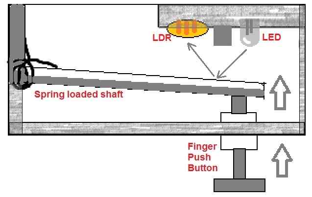
Physically, the circuit oscillates when a Load is connected across the pin "C" of the relay and earth. If the load is less than 100 Ohms the oscillation is significantly fast. And if the load is say about 1K the frequency is normal.
However, I could not understand the circuit nor it is simulating in LT Spice. Could you please explain me how the circuit is sensing the change in resistance of the load. And could you please make the simulation work.
OBJECTIVE:
To make a 555 based automotive turn signal flasher circuit which can detect lamp outage. If not possible with 555 then transistors may be considered.
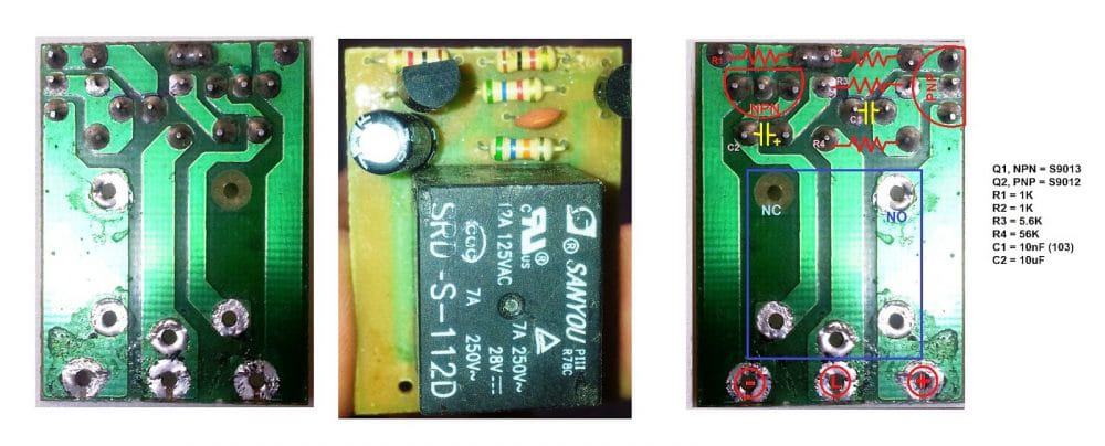
CIRCUIT – A:
Above are the photos and schematic of the circuit. I have physically tested it. It also works on BC558/BC546.
With bench power supply of 12V-2A and load connected at pin (L) and (-), following is the behavior:
· No load, no oscillation
· Pin (L) and (-) shorted, very fast oscillation (relay sounds)
· Load 1 – 1.5K, normal oscillation (about 1.4Hz)
· Load increases, oscillation slows
· Load decreases, oscillation decreases
When using a car battery and 3 x 27W bulbs in parallel the circuit oscillates normally. Even, if a bulb is removed the frequency is unchanged. This means, this circuit does not detect lamp outage. However, the behavior of the circuit with a bench setup may give you some clue to my objective.
CIRCUIT - B
Yesterday, I came across this circuit which has a relay to detect load. I have not yet tested it. I hope this circuit might also help us. Maybe we can replace the relay with a transistor.
Thanks for your help.
Abu-Hafss
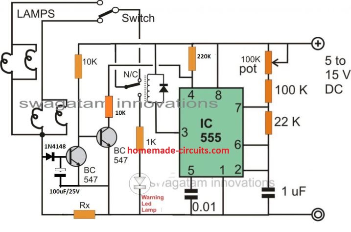
IC 555 based car turn signal indicator with pilot warning lamp:
The required circuit design which is shown below may be understood with the following points:
The IC 555 section is wired in the normal astable multivibrator whose pulse rate at pin## can be adjusted with the help of the given 100K pot.
The two NPN transistors function as current sensor, and IC 555 reset controller.
When power is switched ON, the N/C contacts of the relay connect the turn signal lamps with the 12V supply.
The lamps light up and in the process draw the required amount of current via the Rx resistor.
The above current develops some voltage across Rx which triggers the left BC547 transistor and switches OFF the right BC547 transistor.
The above action resets the IC 555 so that it starts pulsing the relay and the connected lamps.
The LED at its N/O contacts also starts blinking in accordance indicating the correct presence of the lamps at the front and the rear side of the car.
Rx value must be selected such that it develops just sufficient voltage across it to trigger the transistor in response to current consumed by two lamps at the specified rates.
In case even one of the lamps malfunction, the voltage across Rx then wouldn't be high enough to trigger the transistor.
This situation would keep the entire circuit frozen, also keeping the warning LED shut off, providing the necessary malfunction indications to the driver.


Questions & Answers
Flasher circuit with frequency double if bulb failure
Volvo in the 240 and 740 series cars used a much simpler system. Although they have been out of the production since 1993, I believe the cars were wired symmetrically (left/right) and critical external lighting was thus paired. Volvo had a sensor that measured power consumption left/right and front/back to make sure that if braking, the right-side amps = left side amps. Conversely, in the case of a signal light, that front turn signal amps = rear turn signal amps. They had a device under the font dash, driver side, that looked like a cylinder and had all the illumination circuits running through it. If power consumption didn’t match, it illuminated a “burned out bulb” indicator on the dashboard. Google “Volvo light bulb fail sensor”.
Thanks for the car flasher circuit. If the lamps are connected directly to earth as is normal in car indicator circuits, can the current sensing transistor (left hand) be connected at a location physically closer to the module, say, on the positive side of the lights before the indicator switch
Would the circuit have to amended elsewhere
Thanks
Patrick
Hi, which circuit are you referring to? Is it the IC 555 one? Anyway yes you can do that without any amendments.
instead of using 2 bc547 can you use 2 n channel motets
mosfets cannot be used here…
Yes, the 555 circuit.
Sorry, I saw your note about replying to the correct thread, but it isnt obviuos where the correct place is.
Although I see the circuit has now been ammended somewhat from the one I was initially referring to, with a diode on the base of the LH BC547 (from a 22uF cap).
Thanks for your reply
Yes you can place the current sensing stage near the lamps. I have improved the design slightly to ensure that the leftmost transistor remains switched ON even during the OFF periods and allows the 555 flasher to work normally.
The note is to remind the users not to be off-topic while commenting. Your comment is perfectly related to the article topic so it’s more than fine.
Hi
I have the circuit working now as drawn, but I cant make it work with connection point for the sensing circuit (LH transistor) on the positive side of the switch (obviously!). The problem is that in a realworld motorcycle solution the lights go directly to earth on the negative side and the indicator toggle switch is physically remote from the flasher unit.
Need to sense current flow in the positive side of the switch when the indicator switch is closed.
This is what the physical layout is
https://flic.kr/p/2irVTbc
What am I missing?
Thanks for your help, Im enjoying the learning. This is purely for interest ,because its possible to buy electronic flasher units quite reasonably……..its become a challenge!
Patrick
Thanks. I sort of thought of that but was worried about how large the resistor would be, in series in the lamp circuit. Lamp circuit will be running at 4A (2x21W+5W =47W/12V= about 4A.) Is that right?
If the lamp current is 4 amps then the resistor can be approximately calculated using the following formula:
Rx = 1.2 / 4 amps
Hi, thanks for the feedback,
you can probably try modifying the design in the following manner:
Hi
Thanks for the flasher circuit. The 2 version looks like it would fit our classic car (lights are directly connected to ground). Unfortunately the values for the Cs above and below the BC557 are missing. What should they be?
We are trying to retro firt that car wird led flashers. The only consume .4A. Is it correct that RX should be 3 Ohms in that case?
Hi, thanks, and glad you liked it. You can use 10uF/25V for both the capacitors. Yes the RX value should be 3 ohms for a 400mA load
It's my pleasure Abu-Hafss,
In your circuit it could be because of the large value capacitor, not sure though? Otherwise your simulator could be giving wrongs results because any astable circuit may it be using an opamp or any other similar device will never produce an initial delay when switched ON.
if a lower value capacitor was used would that be ok
it will increase the flashing rate…
Hi Swagatam
Thanks, your appreciation is really like an award for me 😉
You may post it in your blog.
The configuration of my op-amp oscillator is almost same as the one shown in figure 29. The only difference is that my design has extra resistor R4, which if removed does not result any change in the output.
Hi Abu-Hafss,
please try simulating the Fig29 "square wave oscilltor" shown the following datasheet of LM324, I am interested to see the simulation results:
http://www.ti.com/lit/ds/symlink/lm124-n.pdf
I'll check the opamp design and try to solve it, if possible…
Hi Abu-Hafss,
Great idea! This will surely work. I'll post it in my blog if you don't mind Mastermindji.
Thanks for this idea!
Actually, I wanted to use a single IC for the circuit preferably LM324. Two op-amps for the lamp outage detection and one for astable oscillator. However, I faced a drawback.
Here is the sq. wave oscillator circuit with an op-amp, frequency 1.4Hz. But as you can see in the simulation, the oscillation starts after about 6.5s. Is there any way to avoid that?
Hi Swagatam
First of all, please spare time to increase the headings of your so that it is easy to find some particular old posts. I understand it is time consuming but, it will quite helpful. It took me quite some time to locate this post. You can also increase one heading "Automotive projects".
Ok, now here is the circuit which I designed for the car signal flasher with bulb outage detection function.
https://dl.dropboxusercontent.com/u/20969135/Flasher%20Circuit%20description.pdf
I had completed this design long time ago but, forgot to report you Ustaad jee.
Hi can you resend it? The link error