The proposed LED strobe light circuit will not only flash a group of LEDs with strobe pulses, but will also create a sequentially chasing effect over the strobing LEDs.
You might be quite familiar with colorful LED strobe lights, and should have seen them pretty commonly in parties and discotheques.
Let's see how we can make one such circuit at home using LEDs. Although these devices use laser light a for the generation of the required strobe effect, using high bright LEDs can also be a good alternative, if many of are included.
Here I have explained a very simple yet very effective LED strobe light circuit which is in fact more innovative than its commercial counterparts as it produces a chasing effect to lights while implementing the strobing flashing effect simultaneously.
Circuit Operation:
The proposed LED strobe light circuit is highly innovative and versatile, it actually can be used in many different applications, like in toys, decoration items, as party lights, and in avionics for displaying warning signals from the airplane (tail light probably).
The circuit utilizes the popular IC 4017 for generating the basic chasing or sequencing output through its outputs.
However the above chasing effect becomes a very primary application of the IC and here we are not looking for just a chasing effect, rather we are interested in the strobing pattern which is induced in the circuit by forcing the outputs of the 4017 IC to flash or blink rapidly as it sequences the lights.
To make the IC output strobe, we introduce another IC 4049 and integrate it to the LEDs in the circuit.
The IC 4049 basically consists of 6 NOT gate. Here two of them are used and configured as an oscillator.
Two of the gates are used buffers for facilitating better grounding effect to the LEDs, while the remaining two are used as another oscillator for driving the IC 4017 clock input.
The strobing oscillator and the clocking oscillator can be varied discretely through the respective pots for creating user defined intriguing LED strobe effects.
The LEDs common cathode termination is not connected to its usual position, i.e. to the ground; rather it’s connected to the output of the buffer NOT gates.
The oscillator from the 4049 IC transmits; rapid high and low logic pulses to the buffers which carry forward the response to the LED cathode.
When the buffer out is high the LEDs remain shut off during that instant. However the moment the buffer outputs go low, the LEDs light up and flash rapidly while sequencing, as the LED cathodes now find the ground path through the buffer low output.
The following figure shows the complete LED strobe light circuit diagram with chasing effect enhanced with a synchronized flashing effect.
Circuit Diagram
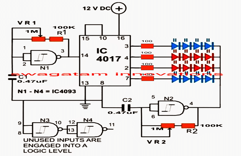
Parts List
| Component | Value/Specification | Quantity |
|---|---|---|
| Resistor | 100 kΩ, 1/4 watt, 5% CFR | 2 |
| Resistor | 100 Ω, 1/4 watt, 5% CFR | 4 |
| Potentiometer | 1 MΩ | 1 |
| Capacitor | 0.47 µF / 50 V PPC | 2 |
| LEDs | Different colors, 20 mA, 5 mm | 16 |
| IC | 4093 | 1 |
| IC | 4017 | 1 |
Calculations:
Frequency of Oscillation:
The frequency of oscillation for the 4093 IC NAND gate RC oscillator is given by the formula:
f = 1 / (1.4 * R * C) Where:
f = Frequency of oscillation (in Hz)
R = Resistor value (in ohms) (VR1 + R1 or VR2 + R2)
C = Capacitor value (in farads) (C1 or C2)
Duty Cycle (for non-symmetrical configurations):
The duty cycle which determines the percentage of time the signal remains HIGH is given by the formula:
Duty Cycle = (R1 / (R1 + R2)) * 100
Where:
R1 = Resistor controlling the charging time of the capacitor
R2 = Resistor controlling the discharging time of the capacitor
For a symmetrical configuration where the same resistor and capacitor are used for both charging and discharging the duty cycle is close to 50%.
Example Calculation:
Suppose the following values are used:
R = 10 kΩ (10,000 ohms)
C = 0.1 µF (0.1 * 10-6 farads)
Substitute these values into the formula for frequency:
f = 1 / (1.4 * R * C)
f = 1 / (1.4 * 10,000 * 0.1 * 10-6)
f = 1 / (1.4 * 10-3)
f = 1 / 0.0014 f ≈ 714 Hz
So, the frequency of oscillation is approximately 714 Hz.
Adjusting Frequency: To increase the frequency you can decrease the value of either R or C. So, to decrease the frequency increase the value of either R or C.
IC 555 Strobe Light Circuit
The following inquiry for making a single IC Strobe light circuit was sent to me by one of the keen readers of this blog, using the concept of IC 555 based LED strobe light effect generator circuit, I have explained the whole issue.
Technical Specifications
Thanks for this guide, I went by my local radio shack and picked up most of these components...Two
things I was not able to acquire was a 1m pot (all they had was a giant
sized pot in the 1m rating) and a 100k resistor (they were out)
I picked up a 4 pack of 22k resistors and wired them in series which gave me 88k which again is close.
I also picked up two 100k pots which i hoped could prove useful.
Knowing full well I don't have the recommended materials on the list I got an effect which didn't much resemble a strobe.
Using the 100k pot there is some variance in the flash speed but it isn't really slow to really fast.
Also my led never goes all the way out using this, again possibly my fault for having the wrong components.
Circuit Objective
What I would like: the ability to strobe a LED three or 4 sharp fast pulses with a pause between bursts
What will the difference between 88k ohms and 100k ohms in the resistor be visually?
I assume a 1m pot will give a much wider range of speed adjustment.
To get pulses with the led do I need an oscillator? with another pot?
Thanks in advance!
Solving the Circuit Objective
Thanks for replying.
I think the above circuit is not very suitable for obtaining strobe light effects, because it is not designed for generating differentiated mark and space ratios.
Your requirement of making the pulses pause for a moment in between sharp pulses would require a PWM kind of design with the IC 555.
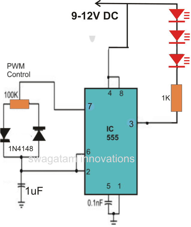
A conventional type of PWM generator using a IC 555 is shown below and can be hopefully used for your type of application.
Here the pot can be used of discretely adjusting the mark/space ratio of the output pulses which in turn helps to optimize the output for obtaining the intended sharp pulses and pauses, this dimensioned output ultimately produces the required strobe effects with the connected LEDs.
IC 555 Strobe Light Circuit Diagram
Video Demonstration
Calculations:
Frequency of Oscillation:
f = 1.44 / ((R1 + 2 * R2) * C)
Where:
f = Frequency of oscillation (in Hz)
R1 = Fixed resistor (100 kΩ)
R2 = Variable resistor (potentiometer)
C = Capacitor (1 µF)
Duty Cycle:
Duty Cycle = ((R1 + Rcharging) / (R1 + Rcharging + Rdischarging)) * 100
Where:
Rcharging = Resistance in the charging path (adjusted by the potentiometer)
Rdischarging = Resistance in the discharging path (also adjusted by the potentiometer)
Example Calculation:
Assume we have the following values in hand:
R1 = 100 kΩ
R2 = Potentiometer adjustable between 1 kΩ and 100 kΩ
C = 1 µF
For R2 = 10 kΩ:
f = 1.44 / ((100,000 + 2 * 10,000) * 1 * 10-6)
f = 1.44 / (120,000 * 10-6)
f = 1.44 / 0.12
f = 12 Hz
For R2 = 100 kΩ:
f = 1.44 / ((100,000 + 2 * 100,000) * 1 * 10-6)
f = 1.44 / (300,000 * 10-6)
f = 1.44 / 0.3
f = 4.8 Hz
So the frequency will vary between 4.8 Hz and 12 Hz depending on R2.
For Duty Cycle:
If Rcharging = R2 = 50 kΩ and Rdischarging = R2 = 50 kΩ:
Duty Cycle = ((100,000 + 50,000) / (100,000 + 50,000 + 50,000)) * 100
Duty Cycle = (150,000 / 200,000) * 100
Duty Cycle = 75%
You can adjust R2 to adjust the duty cycle can range from near 0% to close to 100%.


Questions & Answers
Hi Swagatam, do you perhaps have a pcb layout handy for this circuit?
Hi Pierre, I'll to update it soon, thanks for posting
Can you show a circuit it so that the LEDs have two separate sets – one clear that strobes and the other colored that is sound reactive to music connected to a speaker
you can try the first circuit from this article:
https://www.homemade-circuits.com/2012/03/how-to-make-simple-vu-meter-circuit-at.html
It'll provide the music reactive option….for the strobing effect you can extract a separate string of LEDs from one of the red LED channels.
yes sir i understood. thank you.
ok sir here is the link,
https://docs.google.com/file/d/0B8Qj-AOXys6pZEpKWlQyeHJXdU0/edit
….sorry, correction: the common free ends of the resistors must join directly with the positive supply.
it's perfect but the uppermost resistor is not right, it should come in series with the first LED, just as you have done with the second, third and fourth LEDs, the common anodes of the LEDs should directly join with the positive supply
https://docs.google.com/file/d/0B8Qj-AOXys6pMDB4VVBrcE1wUU0/edit
see the drawing sir
It's not opening, make the "share" option "public" for everyone to view.
ok when load is connect with positive and collector , what will be the connection of N2 side? I mean it will remain open? N2 is now connected to LED negative side.
N2 output will also need to be connected with another TIP122,
base to N2 output via 1K resistor.
all emitters of the 4017 TIP122 will now join together with N2 TIP122 collector.
emitter of N2 TIP122 will connect with ground.
dear sir circuit is working well problem was with 4017 IC. i want to add 4 nos 3w leds. can i do with H1061 or D313 instead of TIP 122? i can choose relevant resistors.
D313 is only 1amp rated, TI122 is 5amp, so only the latter will work
4093 pin 7 to ground and pin 14 to positive to be connected isnt it sir?
yes that's right…
I made this circuit with 0.47= 474k 400v and 2.2M pots my circuit is not working?
explain what is exactly happening….
ok i understood sir….. but 3W LED red green blue and white are having different voltages how can i handle this with above sir?
use different resistors as per the calculations for the LEDs
R = supply – LED(V) divided by current (0.9amps)
not understood sir, emitter to 4017, collector to LED, base ground with 1k?
bases to 4017 outputs through 1K resistors
emitters to ground
load between collector and positive
dear sir i made this circuit it works fine. how can i connect 4 nos 3Watt (red,green.blue white) LEDs they are having different voltages.
dear Jayanath, connect TIP122 with the selected outputs of the 4017 IC and then connect the LEDs across collector/positive of the transistors with individual resistors.
The base of each TIP122 transistors should also have its own resistors (1k will do)
Dear sir in the circuit description it is written as IC 4049 and in the diagram IC is 4093 and the IC pin 11 is not connected?
Dear Jayanath, 4049 will also work, but 4093 is the one we want in the circuit to be…so please ignore 4049. pin11 is an unused (open) output
I would like to change to push button instead of using the VR to change the effect of led. Can u help me to build it because i am not expert in electronic
Hi, I learn a lot with this site .Thank´s. so i got a idea of project to use in airsoft and paintball games. Is a flashbang using high power led´s. When you activate a trigger there is a delay of 5 or 10 seconds and a group of 7 or 10 high power led´s (3w) starting in a high frequency. Based in a 18650 battery . Can you help me ?
Hi, Thanks!
I can surely help you, can you please provide a more detailed info about the requirement, in terms of LED placement, triggering mode etc.
I couldn't get the application very clearly.
correction: connect all free cathode ends of the diodes with N2.
i's simple just do following changes:
replace the 100 ohms with 1k resistors, and connect the bases of the transistors (BC547) with these resistors.
connect the emitters to ground or negative.
connect diodes (anodes) to the bases of the transistors and connect all the free anode ends of the diodes to N2 output.
Now connect LEds with individual resistors to the collectors of the transistors. Done!
hopefully u can shared the design here. so we can share it to the others.
you can use BC547 transistors with 10k base resistors.
i have a same question like jonas. What transistor should i use to powered up my led strips.
Happy to see the old CMOS chips still being used
Tim
these will probably never die:)