The post presents a couple of simple LED intensity controller circuit which may be appropriately configured for specific related applications. The idea was requested by Mr. Chand.
Technical Specifications
I would like to have a circuit designed by you which is very simple and straightforward. This will be incorporated as a stand alone feature in a device which I am working on. What my requirements are - 1. A row of 12 displays (1 seven segment type x 12) 2. A potentiometer with knob to control each display illumination individually ( so in all 12 pot knobs). Each knob increases or decreases the intensity value from 0 to 9 for its individual display. 3. A separate row of 3 displays (1 seven segment type x 3). Function remains the same as point number 2 above. Please let me know the cost for this circuit along with the schematics. Thanks Chand Sharma
The Design
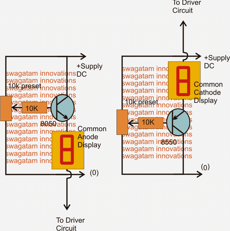
The proposed LED intensity controller circuit may be learned as shown in the diagram.
Two diagrams can be seen, the left hand side may be used for controlling common anode type displays while the right hand side for common cathode types.
The design is basically a common collector BJT circuit where the base potential of the relevant transistors get proportionately delivered across their emitter base terminals.
Thus by varying the potential at their bases the emitter potential is also proportionately varied with a range right from 0V to the maximum supply voltage level (-0.7V).
Each of the following LED intensity controller modules could be used for the proposed 7 segment LED display control application. The preset may be replaced with a pot and its dial appropriately calibrated for getting the intended varying illumination through a range of 0 to 9.


Questions & Answers
Hello Swagatam! I have no other means to contact you but this, I have a Bluetooth module I would like to swap out for a more high powered one pertaining to transmission strength but the one that is mounted to the equipment right now doesn't have the same pinout as the one I've ordered, would it be as simple to just connect the board to the same pins on the new module with wires instead of soldering it in directly?
I don't think your idea of playing with the antenna might work, because bluetooths are entirely different from ordinary RF transmitters, these are associated with high frequency, highly sophisticated digitally coded waves, which have exclusively calculated parameters, if you try to modify the antenna it might result in damaging the circuitry or completely dampening of the transmission.
What has been done in the existing PCB is definitely as per certain strict guidelines which I think shouldn't be disturbed.
My email id is admin @ http://www.homemade-circuits.com
I'm kinda a novice to fiddling with Bluetooth modules too but there seems to be two different form factors or maybe three, they all seem to at least have the possibility to be wired as a simple serial port, will just have to try and see if it works, the upside of using wires rather than the adapter board is that I can have the antenna situated in a better position than it is today… If you shoot me an email at william dot lantz @ gmail dot com I can send you a picture of the equipment and you can see what I mean… Like, who puts a circuit board antenna sandwiched between two multilayer pcbs with ground planes in them? That is like wrapping the entire antenna with a shield… :-
Hello William, this is probably the best place to contact me since I never miss a comment. I may miss out an email though.
As for the bluetooth pinouts, I am sorry I am not very sure regarding the specs for the different models, you might have to check out either the datasheet or the notes provided by the company.
However I personally think these should be in one standard format for all the models in order to keep it simple and hassle free for the users. You can Google for the same to be entirely sure
Could you please design a circuit that counts pulses and control brightness of 12 or more red leds as a result? The input is a sine wave that will vary depending on engine rpm, low rpm = low intensity, high rpm = high intensity. Could this be achieved with pwm?
Thank you, William
the waveform may not be critical, you can integrate any source that may be proportional to the engine speed, diode is not required as it won't make any difference to the results, just feed the input to the base of the shown BC547 transistor and tweak the pot for achieving the best optimized results.
I just thought of something, since my car is a diesel I don't have spark plugs but I have a "w" terminal on the alternator which outputs a sine wave that is directly proportional to engine rpm, does the circuit require any additional components on it's input to work under those circumstances, should I place a diode to rectify the positive half of the sine wave to get pulses instead of a wave with alternating polarity?
Yay! Thank you! 🙂
M1 may also be included for measuring the frequency or the pulses fed at the input
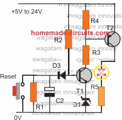
OK for getting just a brightness control with respect to the engine speed you can try the following circuit:
https://www.homemade-circuits.com/2012/05/make-this-simple-tachometer-circuit.html
M1 can be removed and replaced with a NPN transistor whose specs will depend on the type and wattage of the LEDs.
base will go to R8, emitter to ground and the LEDs connected across the positive and collector of this transistor
R3 can be used for adjusting the brightness range of the LEDs.
Yes, a pulse counter to measure engine speed but not as a bar graph, it's for some "effects" lightning… If one could adjust brightness with a potentiometer just for fine tuning that would be perfect… 🙂
could you please provide more details about your requirement,
I guess pulse counter is for identifying the engine speed so it should be in the form of a frequency counter or meter.
and according to me just by judging the LED brightness it could be very difficult to understand the corresponding engine speed, so it should be in the form of a bar graph whose number of LEDs illuminated would provide the required information directly.
Left side circuit not worked
in right side circuit working but 100k potentiometer burning ( smell and smoke).
Which circuit is suitable to decreases as well as increase intensity of LED string of 25 pcs of 150mA LED connected in a Transformerless powersupply Learned from your blog.
both the circuits are perfect, you have certainly done something incorrect in your assembly.
Can I use this circuit to dim 25pcs 3-3.2v 150mA LEDs connected in series?
yes you can do it…