In the following post I have explained a simple yet enhanced 12V capacitive discharge ignition system which derives its operating voltage from the battery instead of the alternator for generating the igniting sparks.
Since it works independently from the alternator voltage, without depending on a pickup coil signal, it is able to function more efficiently and consistently, enabling a much smoother ride of the vehicle even at lower speeds.
Contact Breaker Vs CDI
A capacitive discharge ignition unit also called the CDI unit is the modern alternative for the age old contact breakers, which were quite crude with their functions and reliability.
The modern CDI is an electronic version of the contact breaker which uses sophisticated electronic parts for generating the required arching across the spark plug terminals.
The concept is not complicated at all, the section of the alternator provides the required 100 to 200V AC to the CDI circuit, where the voltage is intermittently stored and discharged by a high voltage capacitor through a few rectifying diodes.
These rapid bursts of high voltage discharges are dumped into the primary winding of an ignition coil where its appropriately stepped up to many thousands of volts for acquiring the required arcing, which ultimately functions as the igniting sparks across the connected spark plug contacts.
I have already discussed the basic electronic CDI circuit in one of my previous posts, though the circuit is extremely versatile, it depends and derives its operating voltage from the alternator. Since the alternator voltage depends on the engine speeds, the generated voltages tend to get affected with varying speeds.
At higher speeds it works fine, but at lower speeds, the alternator voltage also lowers, this results in an inconsistent sparking forcing the alternator and the engine to stutter.
This inconsistency ultimately affects the functioning of the CDI and the whole system starts getting hampered, sometimes even causing the engine to halt.
The circuit of an enhanced capacitive discharge ignition circuit which is discussed here, eliminates the use of the alternator voltage for functioning, instead it utilizes the battery voltage for generating the required actions.
The Circuit Concept
The whole concept for this electronic CDI can be understood by studying the shown circuit diagram below:
The diodes, the SCR and the associated components form a standard CDI circuit.
The high voltage of around 200V which needs to be fed to the above circuit is generated through an ordinary step down transformer connected the other way round.
The secondary winding of the transformer now becomes the primary and vice versa.
The low voltage primary winding is fed with high current pulsating DC generated by a standard IC555 circuit via a power transistor.
This pulsating voltage is stepped up to the required 200V and becomes the operating voltage for the attached CDI circuit.
The CDI circuit converts this 200V into bursts of high current for feeding the input winding of the ignition coil.
These rapid high current bursts are further amplified to many thousands of volts by the ignition coil and finally fed to the connected spark plug for the required arcing and the initiating the ignition of the vehicle.
As can be seen the input voltage is acquired from a 12V DC source which is actually the battery of the vehicle.
Due to this the generated sparks are very consistent without interruptions providing the vehicle a constant supply of the required ignition sparks irrespective of the vehicle situation.
The consistent sparking also makes the fuel consumption efficient, makes the engine less prone to wear and tear and enhances the overall mileage of the vehicle.
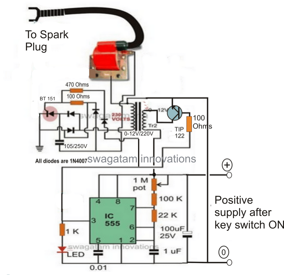
Use a 1K resistor at the base of TIP122...... 100 ohm is incorrectly shown
Synchronizing with Wheel RPM
If you want the above circuit to be triggered by the alternator so that the combustion is ideally efficient and synchronized with the wheel RPM, the above design may be modified in the following way:
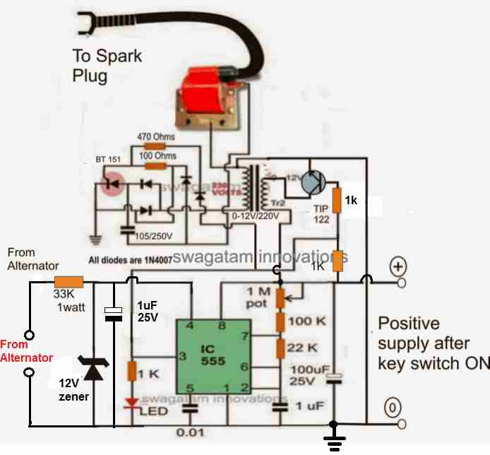
A 1K resistor is used at the base of TIP122...... since 100 ohm is incorrectly shown.
The above configuration may be further modified as shown in the following diagram, which appears to be the most appropriate way of implementing the proposed enhanced CDI circuit for all 2 and 3 wheelers.
How it Works
As we know, the reset pin#4 of IC 555 requires a positive potential to allow the normal functioning of the IC 555 as an astable or as monostable. If the pin#4 is not associated with the positive line, the IC remains dormant and disabled.
Here the pin#4 of the IC can be seen connected with the alternator voltage. This voltage can be of any level from the alternator, it doesn't matter, since it is appropriately stabilized by the 33 k resistor and the following zener diode, capacitor network.
The alternator will generate a positive and negative cycle pulses, in response to each rotation of the vehicle wheel.
The positive pulse will be converted into a 12 V positive feed at the pin#4 which will cause the circuit to initiate and stay activated during the entire positive pulse duration cycle of the waveform.
During these periods, the IC 555 will operate and fire the SCR multiple number if times in short bursts, causing the ignition to fire with higher efficiency and for a sustained period of time during the firing angle of the combustion and the piston.
This will also enable the CDI to work in tandem with the wheel rotation generating an ideally synchronized combustion of the engine and with an optimal efficiency.
Finalized Enhanced CDI Design with PWM Control
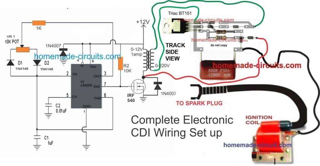
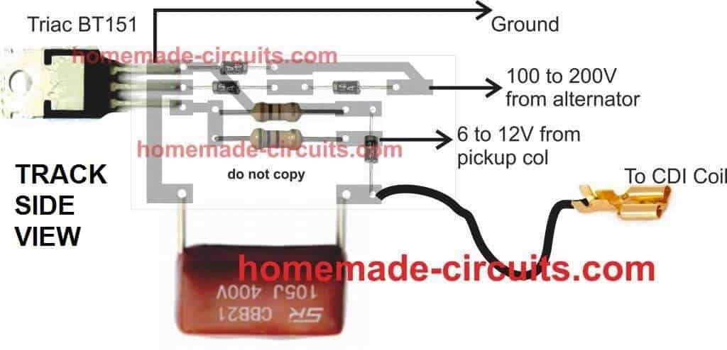
CDI PCB Circuit
Parts List
All resistors are 1/4w unless stated
1K - 1
10K- 1
POT 10K - 1
100 Ohms 1/2 watt - 1
56 Ohms 1/2 watt - 1
Diodes 1N4007 - 9
Capacitors
1uF/25V - 1
0.01uF/50V Ceramic - 1
105/400V PPC - 1
Semiconductors
IC 555 - 1
Mosfet IRF540 - 1
SCR - BT151
Transformer 0-12V/220V/1amp - 1
CDI ignition coil - 1
Video Clip showing the Test Result of the above shown electronic capacitive discharge circuit system
Another Version of Electronic Ignition
The following diagram provides another version of a IC 555 based electronic ignition system, which I got from an old magazine page:
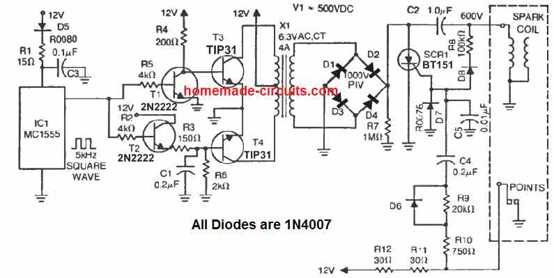
Here, the left side stage which includes the IC 555, 4 transistors and the X1 transformer, form a 12 V to 500 V step up push pull inverter.
The right side section using the SCR BT151, and the associated circuitry forms the capacitive discharge ignition stage.
The design works with the old contact breaker type of mechanism, for timing the ignition and triggering the SCR.
While the contact beaker remains closed, the SCR remains disabled, and this allows the capacitor C2 to charge via the 500 V DC from the inverter output. Next, as soon as the contact breaker opens, the SCR gets its gate trigger via R9, 10, 11, 12, and C4, and it fires causing C2 to discharge across the attached ignition coil primary winding, which in turn causes the secondary of the ignition coil to produce the required high voltage pulse into the spark plug for the required ignition.
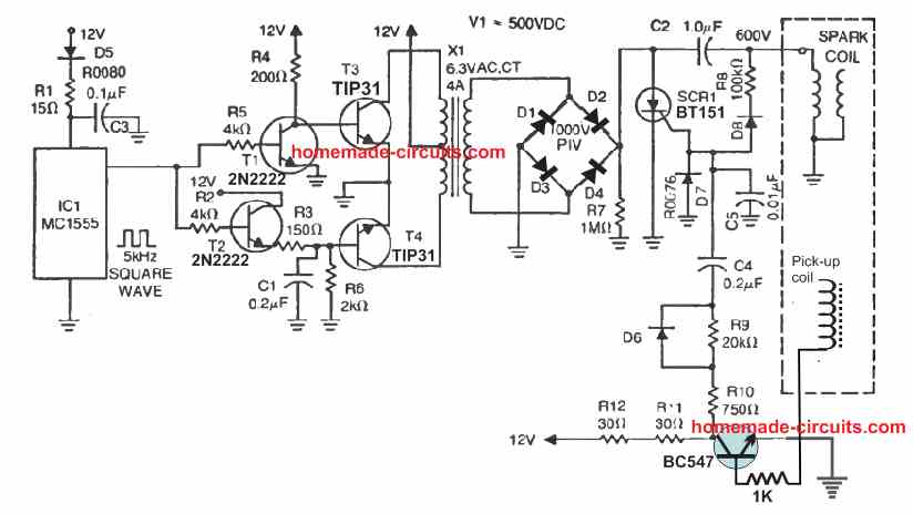
With Pickup Trigger
In modern vehicles we find the contact breaker being replaced with a pickup coil, which ensures a solid state working of the system without any wear and tear. The above electronic CDI design could be also used with pickup coil set up, with the following given modifications.


Questions & Answers
Can a CDI DC circuit be used for a Russian Karpaty brand motorcycle???
two questions,
1 What is the 1Mega pptenciometr used for?
2 In the domde diagram, the zener is fed from the alternator, is it from the starter coils, or from the Karpaty pickup coil??
The 1M pot is for setting the spark frequency.
The supply to the 555 IC is given from the alternator.
If pickup coil is used then the whole 555 circuit will not be required, and the triggering signal can be fed from the pickup coil, using the following design:
https://www.homemade-circuits.com/how-to-make-capacitive-discharge/
Yes, it can be used…
Hi Swagatam,
Does it triggered on the rising edge ( when voltage just want to go up) or the falling edge of the trigger signal?
Instead of the pickup I need to use another external 12V square wave as the trigger and spark should occur on the rising edge.
Thanks in advance.
Hi David,
Yes, the sparks in the above CDI circuits are designed to be triggered with the rising edge of the input pulses, so your square waves will be fine with these circuits…
Good evening sir, i made this circuit but even pin 4 of timer ic disconnected from pin 8 still pin 3 has an output is it normal?
Hi Elmar, pin#4 must be grounded through a resistor or directly, only then pin#3 will be disabled.
also, do you have any ideas on how to set up a spark measurement device to measure the strength of the CDI pulse?
For this application, I think you can select one of the circuits given in the following article and integrate it with an LM3915 bar graph LED generator circuit:
https://www.homemade-circuits.com/2-simple-rf-detector-circuits-explored/
Thanks for this article. Can you tell me what the diagram looks like when you add a tachometer feed? i think i know where, but i’m not sure.
thanks.
The above CDI circuits get triggered by an external pulse, which can be from a pickup coil of the automobile or an oscillator circuit such as a 555 astable, so the feed for the tachometer can be also taken from the same external trigger source which drives the CDI pulses.
Hello sir, can i use this circuit as a cdi unit tester?
Hi Elmar, yes, you can definitely do that!
Thank you sir, i also found your circuit design cdi tester.
No problem Elmar, all the best to you!
Let me know if you face any problems with the implementations…
Hello, thank you very much for your articles, I have something to ask. Where will the power from the control coil go in your design? ”Synchronizing with Wheel RPM”
My English is not very good, I hope you understand and answer.
Hi, referring to the following design, the synchronizing input from the wheel RPM must be connected to the point labelled as “6 to 12V from pickup coil”

Thank you for your reply.
I made the CDI AC circuit as you instructed, it works very well, thank you again. But today, when I connected them to the “”Finalized Enhanced CDI Design with PWM Control”” circuit there was no spark. I measured the voltage at the output of the transformer as 374v AC. I used a 12v – 0 – 12v 3A symmetrical transformer, which steps down the voltage from 220v AC to 12v AC (is this a problem?). The circuit ran for about 3 minutes then the irf540 and the 1n4007 diode connected to it burned out. Can you advise me where I went wrong?
I think the MOSFET burned due to high voltage spikes generated from the CDI coil.
You can try replacing the MOSFET with a TIP122 BJT, because BJTs are more dependable than MOSFETs, and remember to connect the 1N4007 diode, either across the collector/emitter of the BJT or across the BJT collector and positive DC of the circuit.
Also, please connect a 100uF/25V directly across the supply terminals of the 555 IC.
Let me know how it goes..
Hello Swagatam, Thank for share you ideas with us. so i have a question regarding the last diagram. so i need to know can i use 12v-0v-12v / 220v normal transformer for it. that means 50Hz/60Hz one? if it can’t which type of tranformer i can use or can you give me the turns for primary and secondary coils.
And other one is can’t i use trigger pickup coil for your second diagram “Synchronizing with Wheel RPM” ? if it can how can i put it.
Thank you!
Thank you Avish,
Yes, the transformer can be any normal iron-core 50Hz/60Hz step-down transformer, you can see it in the adjoining video.
If you are looking for a pickup coil triggered CDI circuit, then you can simply use the diagram explained in the following article, no need to build the above complex design.
https://www.homemade-circuits.com/how-to-make-capacitive-discharge/
Nice article, You have an idea on how to proceed is there is no battery (one a one magnet fly wheel + CDI). The cdi is down and I would like to realise one with a microcontroller for the advance timing.
If there’s no battery then you can use the following circuit:
https://www.homemade-circuits.com/how-to-make-capacitive-discharge/
Sorry, i have no idea how to implement advance timing with microcontroller.
I would like to charge an extra electrolyte in order to serve as power supply for the microcontroller (Pic or aduino nano (or another controller which boots up fast enough)), which would the calculate the delay (in function of the RPM) to discharge the capacity (without discharging the elco).
You can use a 6800uF/50V capacitor after a blocking diode 1N4007, and feed the DC to your microcontroller through a 7805V regulator.
m saying good night from Cuba.
I present my name is Jorge Luis, I have experience and elctronica and electricity of motorcycles: I am interested in making a DC CDI functional for a bike 200cc 4 timpo. Or it could also be a TCI.
Idida TCI, it works me down very well but when I give it revolutions the engine gets stuck.
Since you doylas thank you for your help,
Hi Jorge,
If you have a pickup coil in your bike, you can try the following CDI circuit, and check the results.
https://www.homemade-circuits.com/how-to-make-capacitive-discharge/
Buenas la pregunta es este sistema de cdi le servira auna moto bicilindrica de cuatro tiempos cb350k4
Good day. I was wondering if you have a version of the CDI circuit that only uses 12-15VDC from a battery?
I do not have a magneto nor do I have an alternator.
It is not possible to provide pulses using a 5 volt transformer in a normal SMPS circuit.
Hi, The first circuit will work exactly as per your specifications. As long as the circuit is powered with 12V, the ignition coil will keep generating the sparks. The frequency of the sparks will be equal to the frequency of the 555 oscillator circuit
hi sorry a little off exact topic but i crossed activator wire for the kill switch that runs directly to cdi and now my engine wont run. sarter motor was engaged while wire was connected what am i facing for repairs? pick up coil and stator design.still getting good firebut wontfullyhit and run
Hi, sorry, I am not an automobile expert so it will be difficult for me to help you with the situation.
hello swagatam first of all i’m sorry because it is weak in english what is the
receiver coil you are talking about? (is it a module) ?
Can you explain with a diagram how to connect this circuit to my 1991 model 1400 engine honda civic? my vehicle has 4 cylinders and electronic ignition system. There is a module in the distributor, should I cancel it. I am a little confused.
Thank you in advance for your help
Hello Burhan, the circuit explained above is intended for 2 wheelers or 3 wheelers, it can be also used for cars but I do have the full information regarding how to connect it to a car ignition system…you may have to consult a qualified car mechanic for the connection details.
Hello there. First of all, I would like to thank you for sharing really nice projects. here is my question. I have a vehicle with a distributor, it has electronic ignition. How can I connect this circuit you shared to my vehicle? my car is 1991 honda civic with 1/4 engine
Hello, you will have to supply 12V DC to the IC 555 circuit. Next, you can disconnect the red wire which is connected to the MOSFET drain, and connect it to your pickup coil output. Finally connect the high tension wire from the CDI coil with the spark plug.
Hi Swagatam Pl check the circuit of the 555 timer of Finalized Enhanced CDI Design with PWM Control, In which the 3 no. pin should be connected to the gate of the IRF540 and not on the pot. also the Pot should be connected to the pin no. 7 and not on pin no. 3.
Please correct if i am wrong, I made as per the circuit provided but the 555 timer burnt out frequently.
This Why I saying is all other circuits above are having the output 3 connected to the transistor.
Regards
Manish
Hi Manish, Using pin#7 as the output is also correct, but mostly pin#3 is used as the output, since it is able to provide both high and low outputs. Pin#7 can produce only low logic but no high logic that is why we need an external resistor (10K) for providing the gate voltage to the mosfet during the OFF times. That said both pin#3 and pin#7 can provide flip flop or oscillating outputs.
I have myself built IC 555 oscillator using pin#7 as the output and it never had any problems….if you want to use pin#3 as the output, you can very well do it.
An example design can be witnessed in the following article:
https://www.homemade-circuits.com/making-adjustable-electromagnet-circuit/
Dear Swagatam
Can you help/ share the schematics of the 35KV spark tester based on the similar lines. What We require is to test the 35KV spark testing on the low current on some meters. I tried to make you version but in the second tranformer from 220 – 12 volt and 12v to 220 Volt the voltages drop 80volt output and the 555 timer IC does not work.
Can you suggest a better circuit diagram using the car CDI.
Regards
MAnish
Dear Manish, I can suggest the above circuits only which can produce well over 27 kv. Both the designs that you tried are well tested by me (you can check the videos). Since you want the current to be low, a 2 wheeler CDI/ignition coil is the recommended option. All the above circuits are very good and tested by me. This CDI circuit is the one which is used in all bajaj motorcycles and rickshaws
Dear Swagtam : What I have done is converted the 12 V supply from transformer to 12V Dc thru connecting a bridge rectifier and feeding it to 555 timer circuit. the output of the 12 volt transformer is AC and again fed tot he input of the 12 to 220 V transformer , in which I am getting 223V Ac output.
Is it correct or not. Please confirm.
Yes that is correct, and it is the correct method of producing low current 220V for the CDI circuit, as explained in the last section of the above article.
Thanks for your great circuits. I have a Kohler 20HP twin cylinder that recently had the ignition coil fail. What I was hoping I might do is adapt your circuit to file the ignition coil salvaged from a 90’s GM. They use two (or three) coils to fire two cylinders in same manner as the Kohler.
What are the pin numbers of IC555 in the circuit pulled from a magazine. The circuit uses the conventional points for trigger.
Thanks
Thank you, you can surely try any of the concepts presented in the above article.
the 555 stage in the last two diagrams are actually IC 555 astable oscillator designs.
You can incorporate the first design from the following article, and replace it in the last two CDI diagrams
https://www.homemade-circuits.com/ic-555-oscillator-alarm-and-siren-circuits/
what if we add more cappacitance?
I need 125 cc dc cdi unit diagram
Which then goes through a bridge rectifier. There will always be a positive voltage at the anode of the SCR all the time the oscillator circuit is working, so it will never turn off after the initial pulse to the gate.
I’ll take off my modification and see if I can get it to work as you have shown.
There’s no bridge rectifier here, even if we had one, still there would be huge breaks in between to enable the interrupted switching of the triac.
Bridge rectifier doesn’t mean the DC is pure, the DC will still be intermittent, unless a filter capacitor is added.