In this post I will show how to construct a GSM based car security system using Arduino, which can lock and unlock car’s ignition system and central lock by sending a password SMS to car from your cellphone
Car theft can be a heart break; it feels like your loved one got kidnapped. It hurts more when an old car which you spend years with it got stolen. Old cars and low tier cars may get stolen often because they offer less security features.
As the time progress new methods are invented to exploit the cars, covering those exploits in mainstream and old cars can cost huge sum of money.
The proposed project can add another layer of security to your car at cheap cost, which might save your car from getting stolen one day.
The proposed project consist of GSM modem (SIM 800/900) which is the heart of the project, an Arduino board which acts as brain of the project.
Few relays interfaced with Arduino board enables and disabled the ignition and central lock of the car.
A valid SIM card with working SMS plan is required to operate this project and try to take advantage of the SMS offers availed by your network provider to reduce the expenses due to SMS.
Now let’s look at the circuit diagram of this cellphone controlled Arduino based GSM car central locking system:
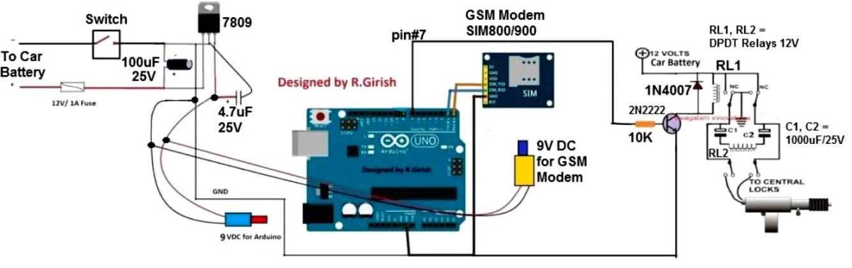
The above circuit is fairly easy to replicate one. The GSM modem is interfaced with Arduino’s Tx and Rx pin.
The Tx of Arduino is connected to Rx of GSM modem and Rx of Arduino is connected Tx of GSM modem i.e. Tx to Rx and Rx to Tx.
Ground to ground connection between Arduino and GSM modem is also established.
A 9V regulator 7809 is added in the circuit to provide to fixed voltage to GSM modem and arduino board as the battery voltage is subjected to change while ignition and charging, higher than 12 volt may damage the boards.
The Arduino’s PIN # 7 is the output to the central lock and ignition lock mechanism.
Arduino Car Ignition lock diagram:
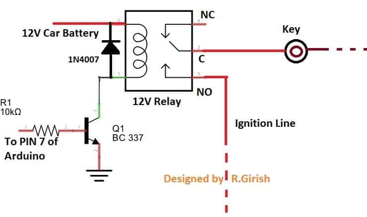
The diodes are connected to prevent high voltage spike from relay due to back EMF.
A fuse must be connected at the input as the short circuit can turn into catastrophic damage to the car.
A switch is provided which may be placed inside the bonnet. It can used to turn off the circuit if you are not planning to use the car for more than a week which will avoid battery drain.
NOTE: If the circuit is turned off (using switch) the central and ignition lock is activated and your car is safe.
Program:
//-------------Program Developed By R.Girish (Diagram Compatible)-------------//

const int LOCK_PIN = 7; // Output to Central Locking/Ignition Relay Driver
const char ACCESS_PASSWORD[] = "qwerty";

// Memory Protection Caps to prevent the 15-byte crash bug
const int BUFFER_MAX = 25;
char cmdBuffer[BUFFER_MAX];
int bufferIndex = 0;

// Runtime State Tracker Flags
bool isUnlocked = false;
bool hasNewCommand = false;
bool isGsmReady = false;
unsigned long initializationTimer = 0;

void setup() {
  // Uses the original hardware pins 0 (RX) and 1 (TX)
  Serial.begin(9600);

  pinMode(LOCK_PIN, OUTPUT);
  digitalWrite(LOCK_PIN, LOW); // Default secure initial state (Locked)

  // Asynchronous 60-second wait to allow GSM to connect to the network
  initializationTimer = millis();
}

void loop() {
  // Non-blocking background network attachment check
  if (!isGsmReady) {
    if (millis() - initializationTimer >= 60000UL) {
      configureGsmModem();
      isGsmReady = true;
    }
    return;
  }

  // 1. Parse incoming characters from the shared hardware serial line
  readHardwareSerial();

  // 2. Process incoming commands safely once a terminating slash is found
  if (hasNewCommand) {
    evaluateCommand();
    hasNewCommand = false; // Reset command trigger flag
  }
}

void readHardwareSerial() {
  while (Serial.available()) {
    char inChar = Serial.read();

    if (inChar == '/') {
      if (bufferIndex > 0) {
        cmdBuffer[bufferIndex] = '\0'; // Safely terminate the string array
        hasNewCommand = true;
        break;
      } else {
        bufferIndex = 0; // Clear index pointers to begin capturing a new command string
      }
    }
    else {
      // Append characters while enforcing strict memory boundary protection caps
      if (bufferIndex < (BUFFER_MAX - 1)) {
        cmdBuffer[bufferIndex++] = inChar;
      } else {
        bufferIndex = 0; // Overflow safety drop: reset buffer on corrupted data
      }
    }
  }
}

void evaluateCommand() {
  // Check 1: Handle system password authentication matching
  if (strncmp(cmdBuffer, ACCESS_PASSWORD, strlen(ACCESS_PASSWORD)) == 0) {
    isUnlocked = !isUnlocked; // Toggle state safely

    if (isUnlocked) {
      digitalWrite(LOCK_PIN, HIGH);
      sendSmsNotification("Central Lock: Unlocked.\nIgnition Lock: Unlocked.");
    } else {
      digitalWrite(LOCK_PIN, LOW);
      sendSmsNotification("Central Lock: Locked.\nIgnition Lock: Locked.");
    }
  }
  // Check 2: Process standard diagnostic system status checks
  else if (strncmp(cmdBuffer, "status", 6) == 0) {
    String statusReport = "System Status: Active & Operational.\n";
    if (isUnlocked) {
      statusReport += "Locks: Unlocked.";
    } else {
      statusReport += "Locks: Locked.";
    }
    sendSmsNotification(statusReport);
  }

  bufferIndex = 0; // Always clear the index to prepare for subsequent commands
}

void configureGsmModem() {
  Serial.println("AT+CNMI=2,2,0,0,0");
  delay(1000);
  Serial.println("AT+CMGF=1");
  delay(500);
  sendSmsNotification("Your car is ready to receive SMS commands.");
}

void sendSmsNotification(String messageText) {
  Serial.print("AT+CMGS=\"+91xxxxxxxxxx\"\r"); // <--- Replace with your actual phone number
  delay(1000);
  Serial.println(messageText);
  delay(100);
  Serial.println((char)26); // ASCII control line terminator character: CTRL+Z
  delay(1000);
}
//-------------Program Developed By R.Girish-------------//
NOTE 1:
The user has to place the password in the code before uploading to Arduino.
//--------------------------------------------------------------------------//
if(!(strncmp(str,"qwerty",6))) // (Password Here, Length)
//--------------------------------------------------------------------------//
Replace the “qwerty” with your own password and change the number 6 to length of your password. For example:
if(!(strncmp(str,"@rduino",7))) // (Password Here, Lenght)
“@rduino” is the password and it has 7 letters (Length). You can place numbers, letters, special characters and combination of these. The password is case sensitive.
NOTE 2:
Replace all the “xxxxxxxxxxx” with car owner’s 10 digit phone number in the code at four places:
Serial.println("AT+CMGS="+91xxxxxxxxxx"r"); // Replace x with mobile number
How to operate this project with cellphone SMS:
• Sending /status/ to GSM modem will send an SMS to car owner’s phone number about the current status of the lock.
• Sending the correct password will toggle the state of the central and ignition lock.
Here is the screen shot:
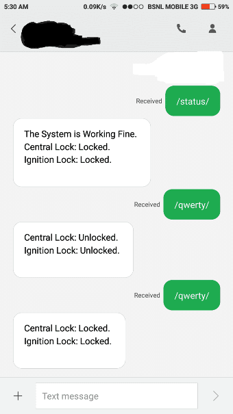
The above result is from the tested prototype.
• Sending /status/ to the SIM card number inserted in GSM modem will send an acknowledgement SMS regarding the current status of the lock to car owner’s phone number.
• Sending the correct password to GSM modem in the above case /qwerty/ is the password, this will unlock the central and ignition lock. It will also send an acknowledgement SMS as shown above.
• Sending the same correct password again will lock the central and ignition lock.
NOTE 3: Start your password with “/” and also end with “/”
NOTE 4: Once the circuit is turned on please wait about a minute. The circuit will send an SMS saying “Your car is ready to accept SMS command” to car owner’s cellphone number. Only then you can send those SMS commands.
If you have any specific questions regarding this GSM car ignition lock, central lock circuit using Arduino, you can send them through the below given comment box

Questions & Answers
How can it be modified to be SMS controlled by more than one phone no.
SMS based circuit is already posted and available in this blog.
else if(!(strncmp(str,”status”,6)))
{
Serial.println(“AT+CMGS=”+923412124417″r”); // Replace x with mobile number
delay(1000);
after this line its giving an error (
exit status 1
expected ‘)’ before string constant
)
I have copied the codes again. please check it now and let me know….
thank u sir .. now its working fine
OK, good!!
sir how can i modify this project as io want that …
when someone trying to open the door it will send me the massage..
2ndly if the iginition started it will again send me a massage tha your “car has been started” and then i will send a command to my cell phon and it breaks the car iginition system to stop the stolling ..hence the rober started ignition ..car will gives no respond even a ignition ..
when i came next i will snd again a command of start ..so relay energize and start terminal manuly working by key system…kindly sir help me out. in programning as well as hardware
Muhammad, you can try the following concept
https://www.homemade-circuits.com/gsm-water-pump-controller-with-call/
and change the relay signal feedback to car door switch feedback….while the main relay switch ON/OFF can be integrated with the ignition start, or central lock