In this article I have explained a simple circuit for enabling the turn signal lamp of any car to carry out a two-way function of DRL lights as well as well the stipulated turn lights. The idea was requested by Mr. Artem.
Technical Specifications
Thank you for your fanaticism with electronics, this is really noticeable through your blog. I've been experimenting with some of your circuits, and everything is okay for now.
Here I kindly ask your professional advise on my project.
Some tiny vehicles have a certain lack of room to place LED lights in order to look fine. For one of those, Nissan Micra i was asked to combine LED Turns and DRL lights without placing one next to another..
Considering a small city car ergonomics i searched the market.
I ordered twin color Y+W 1Watt 350mA LED-Emitters from China, so I could combine both functions by means of some kind a controller at one spot.
And as it often happens, seller did not provide any specs for his product.
4-pin LEDs actually have common "+" so i can not drive six of them in series or implement any known driver. Please advise something useful, I believe you are able to.
Thanks in advance,
Artem,
Moscow,
Russia.
The Design
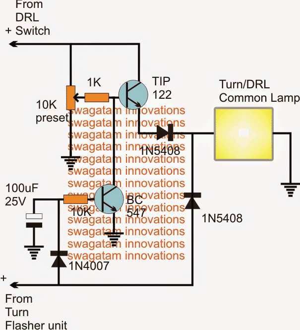
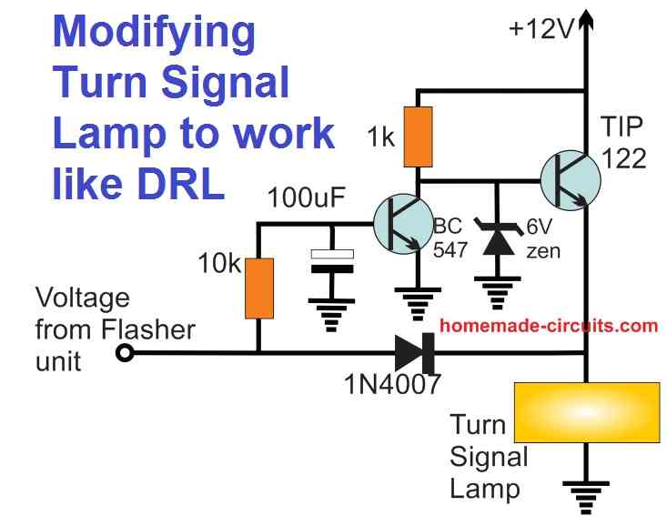
The proposed circuit which combines and enables illuminating DRL and turn signal lamps through a single common lamp can be seen above.
The circuit basically allows the same lamp (preferably LEDs) to implement a dual function of DRL lights as well as turn signals, depending on which one is switched ON.
The DRL switch is supposed to be switched ON permanently, so that the connected lamp illuminates through the TIP122 transistor, and as soon as the turn signal flasher is switched ON, the TIP122 is instantly disabled through the BC547, allowing the turn signal to flash the LED at the given frequency.
The above happens since the BC547 becomes triggered ON through the turn signal switching and keeps the TIP122 base grounded and disabled.
The 100uF/25 plays a crucial role here, and makes sure that the BC547 stays disabled for both the ON and the OFF periods of the turn signal inputs, therefore this capacitor might require some tweaking until the right minimum timing is determined.
Bigger values will work but this might result in a delayed switch ON of the DRL each time the turn signal is deactivated, therefore the 100uF value could need some adjustments.
The 10k preset at the base of the TIP122 may be used for determining the brightness level on the DRL, so this becomes an added feature in the design.
Feedback from Mr. Artem
Thank you for the circuit.
But it seems you get me a little wrong. I wanted the circuit to drive 350ma double color leds, which has single common "+"positive and two "-"negative pins for white and yellow respectively. Both lamps are in single body for ergonomic reasons.
Your suggested circuit doing the job well but we must take two colors with common positive pin in account.
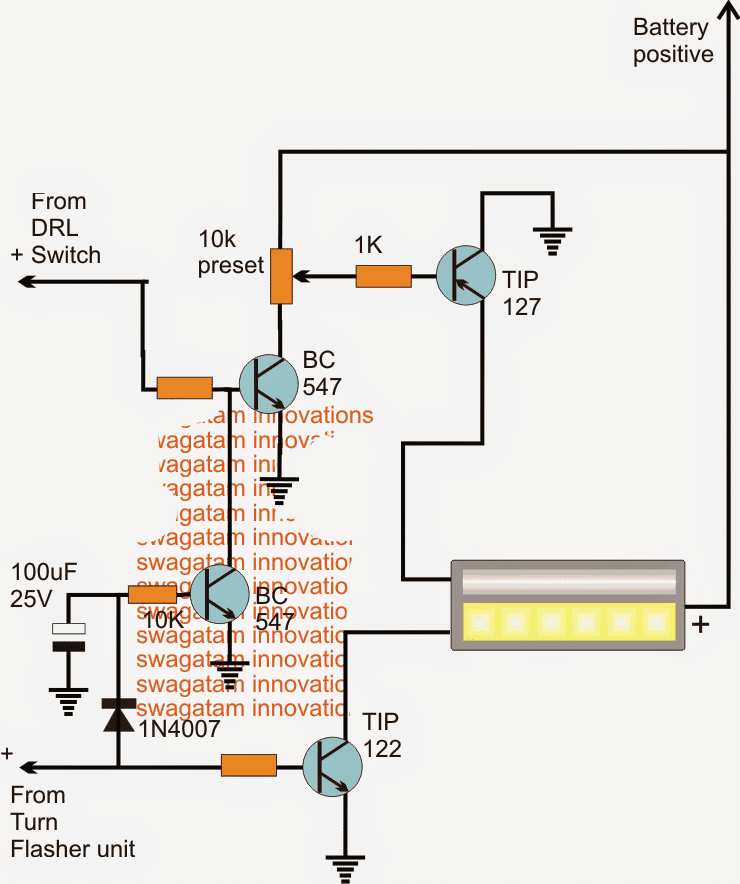
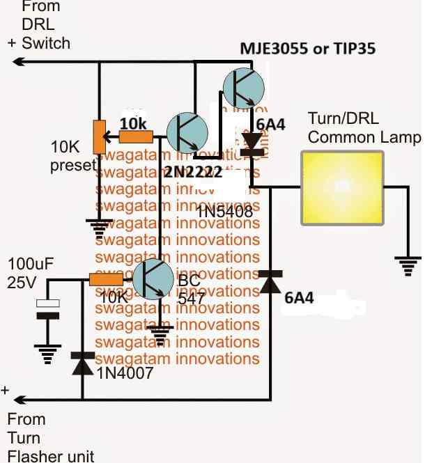
Solving the Circuit Query
As per the above response, the earlier diagram can be modified as shown below for executing the new function.
I have assumed the LEDs to be having the current limiting feature originally, therefore it's not been shown here or included in the proposed designs. Otherwise 5 ohm, 2 watt resistors could be included in series with the respective negative lines of the LED module.
Question Regarding Switchback Driver Controller
The following request was sent by Mr. Dejan Djordjevic
Hi Swagatam,
Can you build a solid state switchback driver controller. You probably know has this works but if needed I have explained.On internet I find some schematics but they use relay and whole assembly is to big. Can you make schematic without relay?
This controller have 3 wires, yellow, black and red.On yellow wire you connect signal from car turn signal, on red connect DRL (daytime runing lights) and black is ground for both.When DRL is ON and you turn ON turning signal DRL will go OFF.When turn signal is switched OFF DRL will automaticaly go ON again.So, this controller is just switching between DRLs and turn signals.You can see one example here
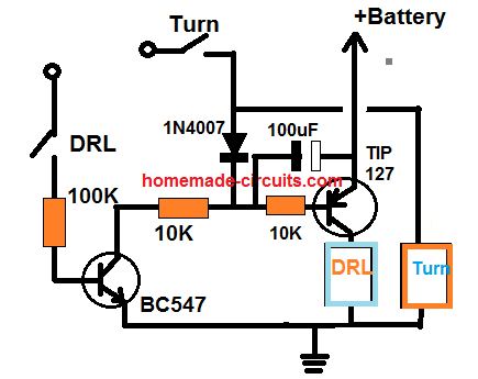
My Reply:
Please check the following diagram, I hope this will do the job
Feedback from Dejan
I tried this circuit and it's working fine.Just small correction if it is possible- can you add a little delay when switching from turn signal to DRL?For example-if turn light is not working for 2 seconds then DRL is switching on.
My Reply:
The delay feature is already present. You can increase the 100uF capacitor value, or increase the 10K near the transistor base to increase delay


Questions & Answers
Hi, I had built your other design for DRL/Turn signals and everything works as intended, but for some reason, after a few mins of running, the TIP 142 starts to conduct to full voltage when running in DRL mode. When you turn on the circuit, the voltage across the LED is about 5v (1k replaced by 47.5k resistor) but after a few mins the voltage increases to 12v… what could be going wrong?
Also in your first design here, can you take the wiper of the pot and feed it to another of the same circuit so you have two DRL circuits with the same output intensity?
Hey, glad you could build it successfully…did you put a heatsink on the TIP142??….most probably it could be blowing off due to overheating.
A simple workaround is to put a 5V or 6V 1 watt zener diode between the base of TIP142 and the vehicle ground. Just make sure to restore the 1k back, or with a 10k maximum value.
I created whole circuit but the TIP122 get so hot that it liquifies the solder. I’m using 1.5 A buld for signal and drl. Please help for 1.5 A rated bulb.
I have changed components, TIP122 –> MJE3055, BC547–> BC639. Resistor 1W rating. But still MJE3055 gets hot on when DRL is used
Thanks for updating the results.
At 1.5 amps the 3055 should not become hot, because it can easily handle upto 3 amp current. Did you measure the current with a meter, please do it and verify the actual current consumption of the bulb.
Its a generic PY21W automotive halogen bulb, it has rating of 21W and 12V, so current should not greater then 2A
Ok, please convert MJE3055 into a Darlington, by combining it with a 2N2222 transistor or any similar NPN transistor and check the results.
I also check current with multimeter. its 0.98 A at bulb
didn’t understand ? can you explain it in bit more details.
Please modify the circuit in this way:
With this circuit, MJE3055 is getting smoked, and damaged. Presvious circuit was working better..
The Darlington pair increases the gain of the transistor and allows it to conduct fully and allows the load to get the full amount of rated current.
Under any case the MJE3055 is not handling more than 2 amps current, so it should not overheat.
If Darlington is not working for you, you can revert it to the previous version.
Are you able to control the brightness of the lamp from 0 to maximum by adjusting the 10k preset?
If you are able to control the brightness from 0 to max using the preset then your transistor ok, otherwise not.
Also, you can try replacing the MJE3055 with a TIP35, which is rated at 25 amps and check if it stays cooler.
Yeah, I can control the brigthness using 10K preset, but MJE3055 have the collector current of 10A, and Base current 6A rating. and bulb is only taking upto 1.0 A or 1.2A max. There any other issue.
The circuit has absolutely no issues. So I am not sure why your MJE is heating up with 1A current. The base resistor 1k is also fine. You can try TIP35 and check the response.
Maybe I missed something but I have a question: I have a Kawasaki Versys and would love to have the indicators stay on (or even better, dimmed) like DRL. Do you have an easy scheme/how-to for this?
So you want the existing turn signal lamps to stay lit dimly, and to illuminate brightly when the turn signals are switched ON, right?
Correct indeed. Or maybe also a circuit design without dimming
I can design a circuit which will keep the lamps glowing with a reduced intensity continuously, as soon as the flasher is switched ON the lamps will start flashing with bright intensity.
Yes please. I’m pretty sure its easy to make. I only know the most basic part of electronics. Not with mosfet or diodes.
The circuit will involve transistors, diodes, and resistors.
Here’s the circuit which you can use for the specified application:
Many thanks! Looks really complicated for a novice like me 🙂
This one is with dimmed DRL right? Because I see something with 6V
If I want without dimmed then I need to remove the 6V resistor?
You are welcome!….for a newcomer this may look difficult but once you get well versed with the component ponouts, you will find it mush easier.
That’s correct, the zener diode value determines the DRL brightness, increasing its value will increase the brightness and vice versa. Removing it completely will produce maximum brightness.
Thank you very much. I will try to find the parts and get started this month! I will let you know
No Problem Ivan, all the best to you!
The latest BMW GS and Honda African Twin always have the other indicator stay one when they indicate. Maybe in this country it’s legal then haha.
Wow that’s strange, if it is not considered illegal in your country, you can use it. As per your previous suggestion you can modify the previous design in the following way:
Why can’t I only use a mosfet? I have an idea in my head so that the indicators pulse cuts off the DRL power. Or am I thinking to easy?
The lamp connected at the mosfet source side will drop at least 5V, and a lamp connected at BJT emitter side will drop only 1V, so BJT is better. Your idea looks good but the main problem is that if you keep the both the turn signal lamps ON as DRL, and then may be flash one of them that will be so confusing to the other vehicles behind you….even the traffic police will not allow this thing.
Hi I used tip122 and 2n5551 transistor . Diode 1n4007 using. Now problem is the led is running dim during the parking And turn indicator light. How to increase the light intensity.
Hi, are you referring to the first circuit? Please provide the specifications of your LED.
Yes 1st circuit. I dont know the led spec but it might be 300mA. 12 v
Did you adjust the TIP122 base preset correctly? because this preset adjusts the voltage for the LED, also try shorting the collector/emitter of the TIP122 and check if that illuminates the LED brightly or not. this will prove whether the transistor has problems or the LED.
I connected the base and emmiter of TIP122. still the led not illuminated to high.. what the problem. should i change to s8050 ?
Yes Swagtam, led not glow fully when connecting emmiter n collector of transistor. Than means tip122 is damaged?
When you connect emitter/collector that means you are connecting the LED directly with the supply. if still the LED is not glowing brightly then your LEd is faulty or may be your circuit connections have problems.
But whenever i directly connect the LED the led, the LED glow full bright. But with the TIP122 circuit the LED not glow fully..
But you said the LED illumination did not become bright when the emitter/collector of TIP122 was shorted? Shorting emmiter/collector is equivalent to connecting the LED directly with the supply.
That means the LED spec is not matching your supply voltage input or the LED may be damaged, you may have to buy a correctly rated LED. The problem is not with the transistor.
Hello there,
I connected 8 power leds for drl. tip127 transistor gets too hot. leds draw 650 ma current. What can I use stronger than tip127.
Hello, How did you connect the LEDs? And what is the voltage rating of the LEDs
power leds 12V and 3W. I use led driver for each led. There are 8 LEDs and drivers in total.
3 divided by 12 gives 0.25 amps, 8 leds in parallel gives 0.25 x 8 = 2 amps. So your circuit is consuming 2 amps and not 650 milliamps, that’s why the transistor is heating up. You can add a big heatsink to the transistor or replace it with TIP142, but still you might need a heatsink
thank you. I connected the relay instead of the DRL light and gave the light through the relay contacts. circuit works very well. I made 2 circuits. I connected it to the vehicle but it does not work synchronously. daytime led lights up milliseconds late than the other. Do you have an idea to have the same reaction in both circuits at the same time.
The delay could due to slight difference in the coil resistance of the relay coils, which can be difficult to adjust or correct.
I have a circuit design request… It’s an automotive application, 12VDC, negative ground.
Using a single, momentary, N.O. pushbutton I’d like to accomplish the following functionality to a 12v relay.
Action 1 – Tap the pushbutton and the relay would pulse/fire quickly 3 times… end of cycle/command
Action 2 – Press and hold the pushbutton and the relay would latch on.
Action 3 – If the circuit is in “Action 2”, a momentary press on the button would reset the relay, readying the circuit for a #1 or #2 action again.
This is a “flash to pass” or “High Beams ON” function, depending upon the duration of the button press.
Action 1 and 2 may be possible but 3 will not be possible using a normal circuit (without microprocessor), resetting will require a separate switch.
hi iam having problems with the last circuit with the dual drl with dimming drl when indicator is turned on please help thanks in advance
please specify the details…
hi. can you suggest a circuit diagram for dusk to dawn control. i have manages to replicate the ones that are used in automatic night lamps which illuminate a couple of led's. Do you have any schematics which can drive regular incandescent bulbs, without using a relay.
You response will be highly appreciated.
I have had a sweep through your blog. Your hard work and inputs are admirable..
Hats off to you. Keep the good work going.
Linus Fernandes
9004805177 / 8698303609 / 9321279202
Hi, thanks!
you can try the following circuit:
https://www.homemade-circuits.com/2011/12/simple-led-automatic-daynight-lamp.html
you will need to remove the LEDs and configure the transistor with a triac for the intended purpose of driving an incandescent bulb, I hope you know how to do it 🙂