A very simple automatic solar light system for illuminating your garden passages can be built using some LEDs, a rechargeable battery and a small solar panel. The system automatically switches ON the lamps at dusk and switches them OFF at dawn.
Main features
Although the following simple automatic solar LED garden light circuit looks simple, it includes a few interesting features which makes this design extremely adaptable, versatile, safe, efficient and long lasting.
The mains features are listed below:
- Automatic charging of battery during daytime with LEDs turned off, and automatic switching ON of the LEDs during nighttime.
- Proper current limiting for the battery to safeguard the battery from excessive charging.
- Current limiting for the LEDs which can be adjusted as per the required number of LEDs.
- Battery over-discharge protection ensures that the battery can never be overly discharged by the LEDs, which in turn ensures a longer life for the battery
How it Works
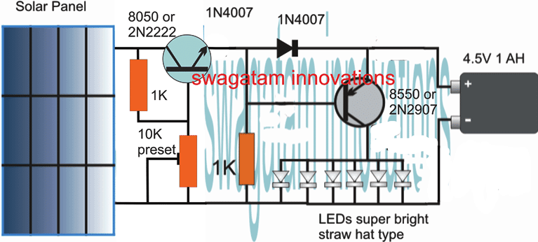
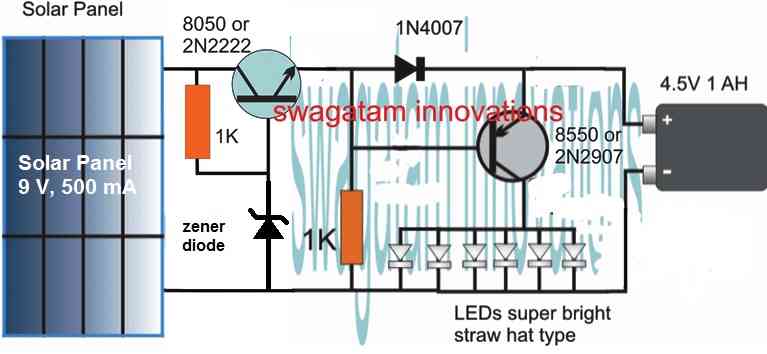
As can be seen in the following circuit diagram, the design basically consists of a solar panel, a couple of NPN transistors, LEDs, a battery, a few resistors and diodes.
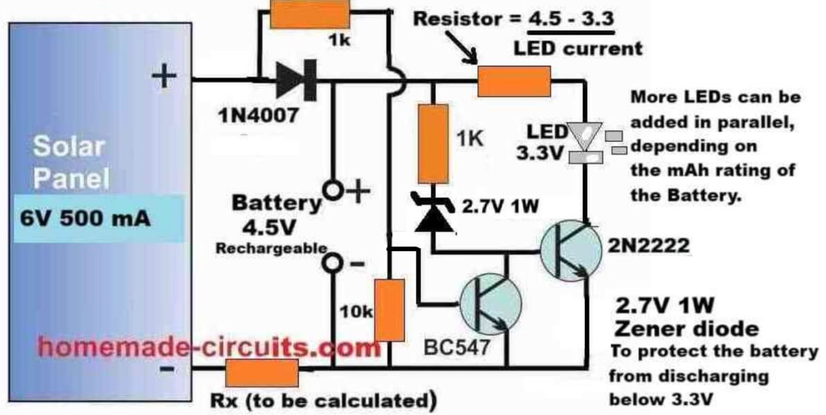
Referring to the circuit diagram above, the working of each of the components can be understood with the following points:
The solar panel supplies the peak voltage of 6 V, at 500 ma during daytime, which charges the battery as long as this voltage is available from the solar panel.
The resistor Rx keeps the charging current to a safe lower level so that even after the battery is fully charged, the minimal current does not harm the battery.
The value of the charging current determining resistor can be calculated using the following formula:
Rx = (Vsolar(peak) - Vbattery(full)) / Icharge
Rx = (Solar peak voltage - Battery full charge voltage) / Battery charging current
Example:
Solar Panel Voltage = 6V
Battery Full Charge Spec = 4.2V
Battery Charging Current (optimal) = 500 mA
Rx = (Vsolar(peak) - Vbattery(full)) / Icharge
= (6 - 4.2) / 0.5
= 3.6 Ω
Rx Power = (Vsolar(peak) - Vbattery(full)) * Icharge
= (6 - 4.2) * 0.5
= 0.9 watts or simply a 1 Watt
However, if you want better protection than just a current limiting resistor, you can opt for a regulated charging system, as discussed in the next design after this explanation.
The BC547 transistor ensures that the LED driver transistor using 2N2222 remains turned off, as long as a base voltage of at least 0.6 volts is available from the solar panel.
Meaning, until the voltage from the solar panel has not dropped below 0.6 V, the BC547 transistor remains switched ON, causing the base of the 2N2222 to remain grounded, and turned off.
Therefore, until it is significantly dark or until the solar panel is able to supply at least 0.6 V to the BC547 base, the 2N2222 remains switched off, which in turn causes the LEDs to remain shut off.
Once the solar panel voltage drops below 0.6 V, the BC547 transistor slowly starts turning off, causing the 2N2222 to slowly start turning ON.
As the 2N2222 slowly turns ON, its collector LEDs also begin slowly getting illuminated, using the stored power from the battery which was charged during the daytime using solar energy.
Once it is completely dark and the BC547 is fully turned off, the 2N2222 BJT conducts fully causing a full illumination on the LEDs.
The LEDs now illuminate fully using the stored energy from the battery, and the battery slowly starts depleting its power through the LEDs.
The battery keeps the LEDs illuminated until the battery voltage has drained down to its lowest discharge level, which happens to be around 3 V for the 4.5 V battery shown in the diagram.
However, as we know that a BJT can conduct only until its base voltage is around 0.6 V higher than its emitter voltage.
But since the base of the 2N2222 is clamped with a 2.7 V zener diode, it means that the base voltage of the 2N2222 needs a minimum of 2.7 + 0.6 = 3.3 V to enable its proper conduction.
So, when the battery voltage drops to around 3 V, the base of the 2N2222 does not satisfy the minimum required base voltage of 3.3 V and thus it turns OFF.
In this situation the LEDs also shut off, preventing any further discharge of the battery, which protects the battery from over discharging.
A series resistor with the LED positive line ensures that the LEDs are protected from over current and are always safely illuminated without any possible harm or damage.
The limiting resistor can be calculated using the following formula:
R = (VBattery - VLED) / ILED
R = (Battery Voltage - LED forward voltage) / Total LED safe Current.
Example:
Battery Voltage = 4.2V
LED Voltage = 3.3 V
LED Current = 20 mA
Then,
R = (VBattery - VLED) / ILED
= (4.2 - 3.3) / 0.02
= 45 Ω
R (Power) = (4.2 - 3.3) * 0.02 = 0.018 watts or simply a 1/4 watt should work...
The next morning when sunlight falls on the solar panel, the BC547 yet again disables any conduction of the 2N2222 BJT and the LEDs, initiating a fresh charging cycle for the battery.
The above cycle now keeps repeating each day and night providing the required automatic illumination of the garden premise using this simple, versatile garden LED light circuit.
You may also like this PIR Controlled Solar Garden Light Circuit
Solar Garden Light with Regulated Battery Charging
The following diagram shows how the above simple design can be upgraded into an automatic solar garden light circuit with regulated battery charging.
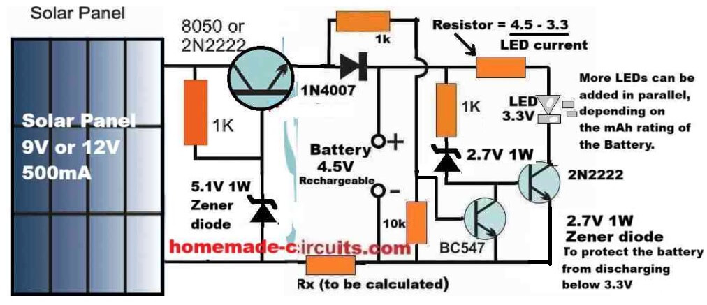
The automatic operation of the LED lamp stage is actually exactly identical to our previous design, the only difference being the inclusion of the voltage regulator stage incorporating another 2N2222 BJT in an emitter follower configuration.
As we know that in an BJT emitter follower configuration, the emitter voltage of the BJT follows the base voltage, meaning the emitter terminal of the BJT replicates its base voltage.
However, due to the BJT's internal base/emitter voltage drop of 0.6 V, the emitter voltage is always around 0.6 Volts lower than the base voltage.
In the above regulated solar garden light circuit diagram, since the base of the left side 2N2222 emitter follower regulator BJT is clamped with a 5.1 V zener diode, means that its base voltage is fixed at 5.1 V, regardless of the solar panel voltage.
Therefore, the emitter voltage of this regulator 2N2222 BJT will be always fixed at around 5.1 - 0.6 = 4.5 V.
This 4.5 V fixed output is what we require for a safe charging of our 4.5 V battery, which means the 4.5V battery can be never charged above its full charge level of 4.5V, ensuring a safe regulated charging for the battery.
Parts List
- Resistor, 1k, 1/4 W CFR = 3
- Resistor, 10k 1/4 W CFR = 1
- LED limiting resistor and Battery limiting resistors as discussed previously.
- BJT 2N2222 = 2
- BJT BC547 = 1
- Rectifier Diode 1N4007 = 1
- Zener Diode 5.1 V 1/2 watt = 1
- Zener diode 2.7 V 1/2 watt = 1
- LEDs as per requirement and battery capacity.
- Solar Panel = 9V to 12V, 500 mA
Using NPN Transistors
The above explained designs can be also replicated using two NPN transistors as shown in the following diagram:
Solar Pathway Light Circuit with Constant Voltage
If a Li-Ion battery is intended to be used for the above explained circuit, a constant voltage feature becomes crucial for safeguarding battery life and prolonging it.
The following circuit show how this may be done by adding a simple voltage follower regulator circuit:
If a 3.7V Li-Ion battery is used, make sure to adjust the 10K preset to achieve precisely 4V across the output points where the battery is supposed to be connected, do this adjustment without connecting the battery.
The 4V level ensures that the battery is never overcharged (at 4.2V) and this also allows the circuit charge the battery without a constant current supply.
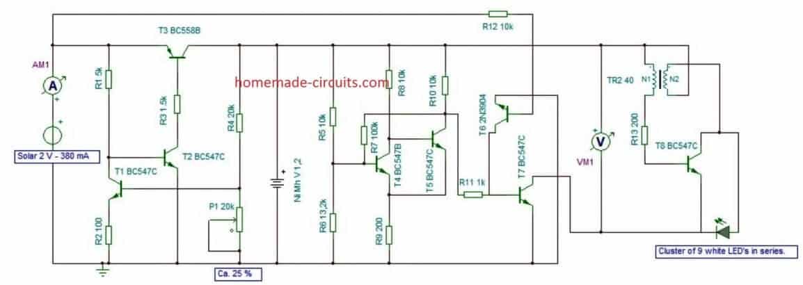
1.5V Solar Garden Light with Enhanced Features
The following solar powered garden light was designed by Mr. Guido which includes additional features such over charge and low charge cut off for the battery and with a Schmidt trigger.
This ensures that the connected battery is never allowed to charge or discharge beyond unsafe levels.
The main attraction of the circuit is the use of a single rechargeable AAA penlight cell, which is able to light up a 3.3V high bright LED through an attached Joule thief circuit.
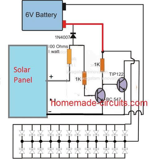
High Power 12V Garden Light Circuit
The following image shows a high power automatic garden porch light circuit using a 12V 7 Ah battery. The LEDs used are high power 1 watt LED each. Since 9 LEDs are used the total power output becomes 9 watt.
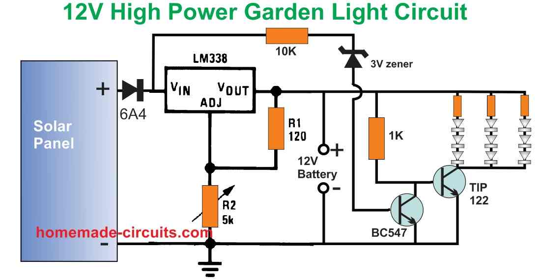
The circuit is designed to automatically switch ON the LEDs when the darkness level drops sufficiently and the solar panel voltage drops below 3 V.
The LED series resistor values can be calculated using the following formula:
R = Battery Supply - LED FWD V Drop / LED Current
= 13 - (3.3 x 3) / 0.3
= 2.1 / 0.3 = 7 Ohms
Resistor wattage = 2.1 x 0.3 = 0.63 watts or 1 watt.
The solar panel can be rated at 18V, 3 amp. The battery specification is 12V, 7 Ah. The solar panel output voltage is regulated using the LM338 voltage regulator.
Make sure that the 5K pot of the LM338 circuit is precisely adjusted to produce 14V for charging the 12V battery.


Questions & Answers
Hi Swagatam
Regarding the last circuit “High Power 12V Garden Light Circuit”, this is a very good design and works very well. I would recommend this to others, thank you. I have already built multiple of these, for not only me, but others too.
However, would it be possible to replace the Zener diode transistor change over circuit (10KΩ resistor, 3V Zener and BC547 transistor) with a 741 design, and allow for a trim pot to control the lighting trigger level, rather than rely on the fixed Zener solution?
I would like to upload the marked up area in the schematic that I refer to, but am not able to in this dialogue box.
Many thanks in advance
Thank you Duncaan, for updating the wonderful results, I am glad it is working for you.
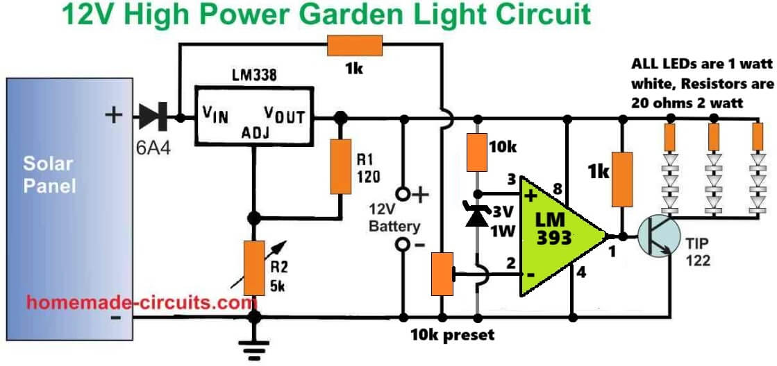
And here’s the full schematic of the design that you have asked….let me know if you have any further doubts regarding this circuit:
Hello.
I am electronic engineer also. I am in Canada know but originally i am Iranian.
I look at your circuits . I don’t work in designing field but i work in repair and service field and i was in one Solar Farm installation in my country . 10 MW .
Best Regards.
Mohammad.
Thank you for your introduction, glad to know about you!
All the best to you…
Good afternoon i did email you previously and thank you for your reply but i am struggling to convert the 6v solar panel with a x3 1.5v rechargeable batteries onto a circuit board having never done this before so want to make sure when i do my first circuit board ad transfer you circuit diagram i will be a lot better infirmed. So is there anyway you can send me a overview of how i would transfer this onto a circuit board if you have the time please?
Hi Kevan,
You will have to connect the 3 cells in series to make them compatible with your 6V solar panel.
However, if this is your first circuit project then I am afraid you will have to first learn how to solder the parts on a PCB.
There are many good youtube videos which you can refer to, to learn how to put components on a PCB and assemble them by soldering.
Please let me know if you have any further doubts…
Hi. I haven’t successfully completed one of your previous circuits with the solar panel yet because the panel has a broken wire and the leds stayed on and flattened my battery.
I’ve now fixed the solar panel, however i wanted to ask whether and if the diodes actually are zenner in this first circuit. “However when dusk sets in the solar voltage begins to drop, and when it drops below the zener diode rating”. I looked up the data sheet for the 1N4007 diode and there wasn’t any mention of a specific reverse breakdown voltage or the name zenner anywhere. Thanks Tony
Hi, I am extremely sorry for the confusion. There’s actually no zener diode in the first circuit, I will do the necessary corrections in the explanation soon.
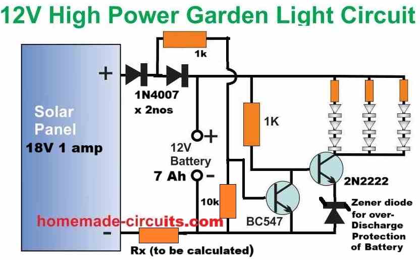
Also, please try the following diagram instead, because in the above first diagram the LEDs will start illuminating as soon the solar panel voltage starts dropping below 4V, which is not good. In the following diagram, the LEDs will illuminate only when the solar panel voltage has dropped below 1V.
Please let me know if you have any further questions…
That was an extremely fast reply. Thank you. I can see that this link to the 18v panel and 12v battery will be very useful in the future as mine and most other general use solar panels for boats, camper vans etc are either just under 20v output or 40v output….and in this linked diagram and circuit i assume the zennr breakdown voltage must be around 11.5v. I will probably try this one later….however, the first circuit was perfect for the little panel i had spare (6v), 4.5v battery from a broken tech piece and a set of led mushroom lights that i already had that were originally powered by 3 series button cell batteries. I’m pretty sure i should be able to tweak the circuit now I’m sure a zenner wasn’t required in this more simplistic circuit. Cheers, Tony
No problem at all, I am always happy to help!
Your are absolutely correct with your assumptions, regarding the previous circuit design.
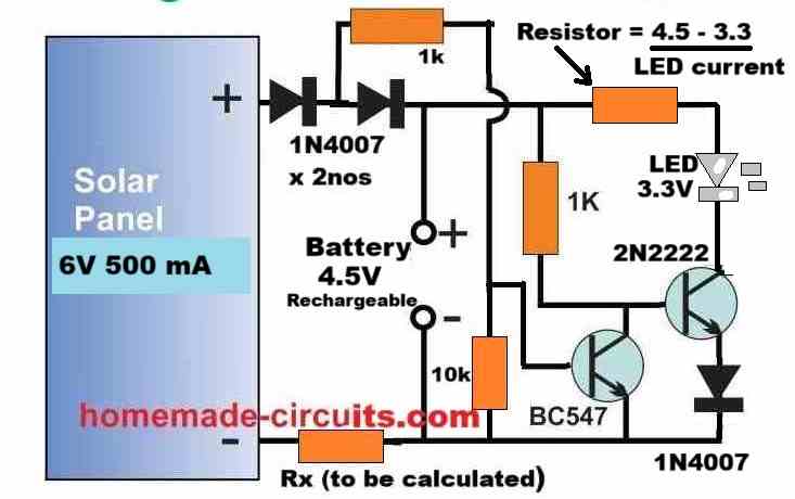
For your 6V application you can try implementing the following design:
If you can tell me the mAh rating of your rechargeable battery, then I can provide you with the value of the Rx resistor…
Cheers!
Thanks for the new 2 npn resistor circuit, i think the amps coming out of the small solar are pathetic and this second circuit might be more sensitive to this. Two questions that probably come out of my lack of understanding of electronics..1. Could you explain why the first diode coming aways from the solar panel is necessary (i don’t want to lose any more volts than is absolutely necessary…. and 2. The final diode after the 2n22222 transistor looks like a throw back….or forward… to not depleting the battery too much…in which case would this be a 5v zener in reverse? Sorry if I’m seeming stupid now. Inexperience. Cheers
Thanks for the insights! You are absolutely correct, the diode which is connected to solar panel positive is simply not required, because the second diode can handle an accidental reverse polarity situation as well, and safeguard the components.
So you can safely eliminate the diode associated with the solar panel positive terminal.
Yes, the 2N2222 emitter diode can be replaced appropriately with a zener diode to prevent over discharge of the battery.
Let me know if you have any further doubts!
Hi Swagatam, i tried 12v high power garden light using lm338,but i cannot get it work.Please help me to get it work. Thank you.
Hi Vladimir, could you please tell me what exactly is happening with your circuit, I will try to solve it…
Hi Swagatam, Thank you for quick respond. Sorry, i forgot to put a diode like you mention. After this simple fix it is working now. Is it possible to put a diode in your on line site diagam circuit? Thanks again. God bless you!!!
Thank you Vladimir, Glad it is working now. Which diode are you referring to? Is it the zener diode at the base of the lower BC547 transistor?

Hi. the diode is not in circuit. it mention in red under circuit.
“Please remember to connect a Diode between R1 and the battery positive.”
So i did like you said
Ok thanks, understood, yes that diodes is important to make sure that the battery does not self-discharge through the 240 ohms and the potentiometer.
Hi Swagatam, without added diode led’s did not turn on at dark time, that was my problem. But i did not think about discharging battery also with out diode….
Thank you Vladimir,
The actual purpose of that diode is to prevent battery discharge through the LM338 resistors, but even without the diodes the LEDs should have illuminated?
Anyway, I am happy the circuit is now working for you.
Swagatam… I bought several landscape lights and these are 1.2v ni-cad units. They didn’t come with circuit diagrams and two have failed after a week or two. I suppose they could be faulty due to infant mortality and the store will exchange them for new units but it would be nice to tinker with them if I knew the parts layout and specs. Thanks for providing this webpage.
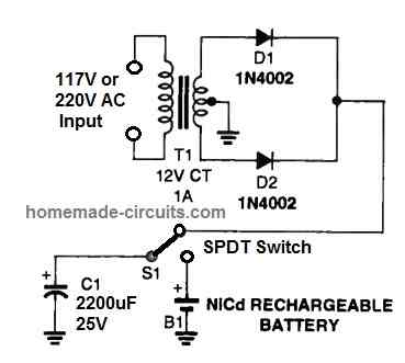
Thank you Ozzie, you can perhaps try the following design to revive the dead Ni-Cd cells and try experimenting with them:
Hi Swagatam,regarding 3.7V Li-ion voltage circuit. I am trying to make solar light powered with 6Ah Li-ion unprotected battery, which will turn on only at night, and only when PIR sensor detects movement. LEDs power should be about 0.5W and I expect ~60lm from them. What is the most efficient way to make this, as I need long last device without additional charging?
I saw all topics for solar lights and PIR sensors, but did not find any that I know how to modify for my requirements. Do you maybe have a PCB design that will fulfill those requirements?
Thank you in advance and best regards,
Tibor
Hi Tibor,
here is the complete circuit diagram that will fulfil all the specifications you need in your design:
Hi Swagatam,
this looks like something I need! Thank you very much for your help!
Also, I want to know why you choose 9V and 1A panel? Isn’t 1A not enough for 6Ah capacity?
And if I want to use 6V panel, whould it still work in this configuration?
Btw. I saw you wrote LED 1W, what will be the difference if I use 0.5W LED?
Thank you!
No problem Tibor, I am always happy to help!
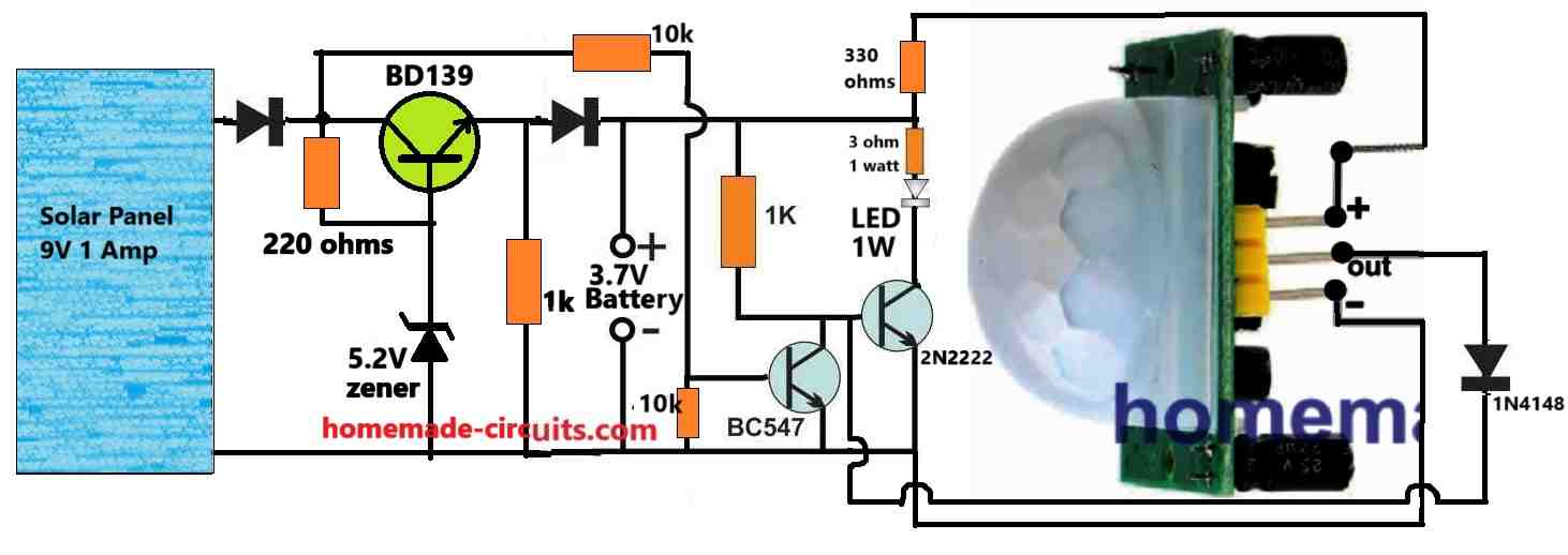
In the shown diagram, the two diodes and the transistor combined will drop around 2.5V, so the panel voltage has to be at least 2 volt higher than this drop.
If your battery is 3.7V then its full charge level will be around 4.1V, that means the solar panel must be rated at 4.1 + 2.5 = 6.6V, but considering the sunlight fluctuations it is recommended to add 3V more to the panel, so it must be around 6.6 + 3 = 9.6V or higher.
Yes, for a 6Ah Li-ion battery 1 amp current is quite low, in that case you can consider adding more panels in parallel and upgrade the input current to 3 amps.
In that case the transistor will need to be replaced with a 2N3055 and the base resistor reduced to 50 ohms 1 watt.
The diodes can be 6A4 diodes each.
Also, there’s one mistake in the diagram. The 1K connected with the base of the 2N2222 must be removed because we want to activate the 2N2222 only through the PIR, and not from any other source.
For the LED, you can use any desired 3.3V LED, just make sure to change the series resistor accordingly.
Thanks Tibor,
To get accurate results you will need a two transistor circuit which will ensure that the LEDs do not turn ON until it is totally dark outside.
An additional LDR might not be required, we can manage with the solar panel voltage for the detection.
I have understood your requirement and will design the entire circuit soon and let you know, with all the part specifications.
Sir: where does one get all these components. Thanks
Hello Leon, you can search for the following phrase, you may find many good electronic stores for buying electronics spare parts:
buy electronic spare parts
Sir: need a circuit board for a LED lite string 3-5 volt dusk to dawn for a cross I am trying to light .Would like a board made in the USA. have a 12 volt solar panel on the cross. Need your recommend as I have failed many times because at 83 years old I have tremors bad and soldering is areal struggle. Thank you
Hello Leon,
According to me, the last circuit from the above article will be most suitable for your application. If you are having difficulty soldering, you can hire somebody to do it for you. Please let me know if you have any further questions.
I’d like to know how to convert a battery Operated garden stake globe into a solar powered garden stake globe (using a dollar store solar-lit garden stake). Is this possible? What should I do?
EB, do you have a dc voltmeter? if yes then we need pictures of your project. if the original light uses two bateries that would be 3 vdc, if the dollar store uses one that is only 1.5 .
I do not know the voltage and current specifications of the units you have mentioned, so it is difficult for me to suggest.
Hi swagatam
I need your help, for making a circuit of AUTOMATIC CUT OFF WHEN SOLAR CELL PLACE UNDER THE SUN AND TURN OFF LIGHT & CHARGE BATTERY. WHEN I PLACED THE SOLAR CELL UNDER THE SHADOW THEN AUTOMATIC LIGHT TURN ON, on battery
Hi Kartik,
Automatic cut off is not required. You can simply use a LM338 IC regulator and set it to provide a constant voltage to the battery which should be slightly lower than the extreme full charge level of the battery.
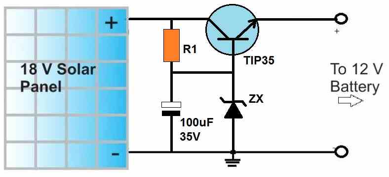
Here’s the design which you should build:
Thanks Swagatam, Let me try this solution…
Sure, no problem.
I have bought a 3W 6V solar panel what value of diode,resistor and transistor and led bulb should I use for a solar lighting system project. Can you please tell the assembling diagram too.thanks
You can try the following setup:
Adjust the zener diode so it creates around 4 V across the battery terminals (without connecting a battery)
The battery can be any 3.7 V Li-ion battery
Hi Swagatam, many thanks for the awesome website and content!
The wife bought some LED garden lights, but they don’t come with solar charging. I’ve decided to try and build the solar charging + automatic dusk toggling. These lights come with an IP44 3x AA enclosure, and I’m wondering if I can reuse them. The LED lights are 10x 0.3W. Based on this, am I correct in thinking I can use the second circuit listed under the “Circuit Diagram” title, without modification?
Cheers!
Hi TJS,
yes you can use the second circuit, however if you find the 2N2907 heating up a bit then you can replace it with a BD140 or TIP32 transistor. If you find the brightness is not optimal, you can try reducing the a 10 ohm resistor or the 1K resistor with some trial and error.
Hi Swagatam, many thanks for the quick response. I’ve taken on board your suggestions for alternative components.
What changes would be needed to use a CL-SM3P cellevia power solar panel? Is it too powerful for this application?
Thank you TJS, can you please tell me the specifications of the solar panel in terms of its voltage and current? I will try to solve it for you.
Hi Swagatam, sure thing. Here goes:
Really appreciate your help!
Thank you TJS,
17V is a lot for a 3.7 V battery. If your battery is a 3.7 V rated then either you may have to use a step down regulator to control the voltage or use a 8 V solar panel instead.
Understood sir. I’ve found a 6V 2W panel. I believe this will work with the circuit we have been discussing.
yes, that should be OK, however if your 3.7 V battery would still require some kind of voltage regulation so that it is not overcharged beyond 4.2V. I would recommend the following type of simple regulator. The resistor can be a 1K resistor, the transistor can be BD139 and the zener diode can be selected such that the transistor emitter output generates around 4.2V. Check the 4.2V after putting a load resistor of 470 ohms across the emitter and ground of the circuit.
Hi Swagatam. Sorry, but I’m a little confused. Where do the lights go, in the diagram you’ve shared?
Hi TJS, here is the complete circuit diagram with the regulator. The zener diode value should be selected such that a full charge level of the battery is available across the points where the battery needs to be connected. This must be checked and set without the battery connected.