In this article I have compiled 10 interesting yet simple LED chaser circuits, which not only create beautiful running light effect but are also easy to build.
These primarily incorporate LEDs as well as mains operated bulbs through triacs. The proposed circuit is transformerless and is thus a lot compact and light weight.
Which LED Chaser Circuit Should You Choose?
In this article you will find different types of LED chaser circuits which can be built using popular ICs like the IC 555, IC 4017 and 74LS164. Each circuit produces a different type of running light effect. The following guide below will help you to select the right circuit for your requirement.
- For a simple running LED effect: You choose the basic IC 555 and IC 4017 LED chaser circuit.
- For controlling more than 10 LEDs: You may choose a circuit using two or more IC 4017 stages, depending on the required LED count.
- For the Knight Rider scanning effect: Grab the Knight Rider LED chaser circuit which produces a scanning light pattern.
- For a fading LED effect: You may go for a fading LED chaser circuit that gradually increases and decreases the brightness of the LEDs.
- For different LED sequencing patterns: You can choose a suitable 74C164 or 74LS164 based circuit.
- For forward and reverse LED movement: You may select the reverse-forward LED chaser circuit designed for this effect.
- For controlling LED lamps or bulbs: Choose a circuit specifically designed for the required load and supply voltage. Check the output driver ratings before connecting the load.
| Your Requirement | Recommended circuit |
|---|---|
| Simple running LEDs | 555 + CD4017 |
| More than 10 LEDs | Two CD4017 ICs |
| Knight Rider scanning effect | 555 + CD4017 with diode network |
| Gradually fading LEDs | LED chaser with transistor stages |
| Different sequencing patterns | 74C164 or 74LS164 |
| Forward and reverse movement | Reverse/forward LED chaser |
Before building any of these circuits, you must always check the supply voltage, component values and maximum output current specified for that particular design.
How Does an LED Chaser Circuit Actually Work?
An LED chaser circuit is a simple electronic circuit which makes a group of LEDs glow one after another. This gives you a running light effect which is used in decorative lights, car lights and many other electronic projects.
A simple LED chaser can be made using IC 555 and IC 4017. The IC 555 produces clock pulses and the IC 4017 uses these pulses to switch its output pins ON one by one. When LEDs are connected to these outputs, then they start glowing one after another and produce the chasing effect.
The chasing speed can be changed by adjusting the resistor or capacitor values connected with the IC 555. Other types of LED chaser circuits use different ICs and components to produce special effects like forward and reverse running lights, scanning lights and fading LEDs.
Below given are different LED chaser circuits which you can try building according to your requirement. Some circuits are simple, while others use more components to produce different types of running light effects.
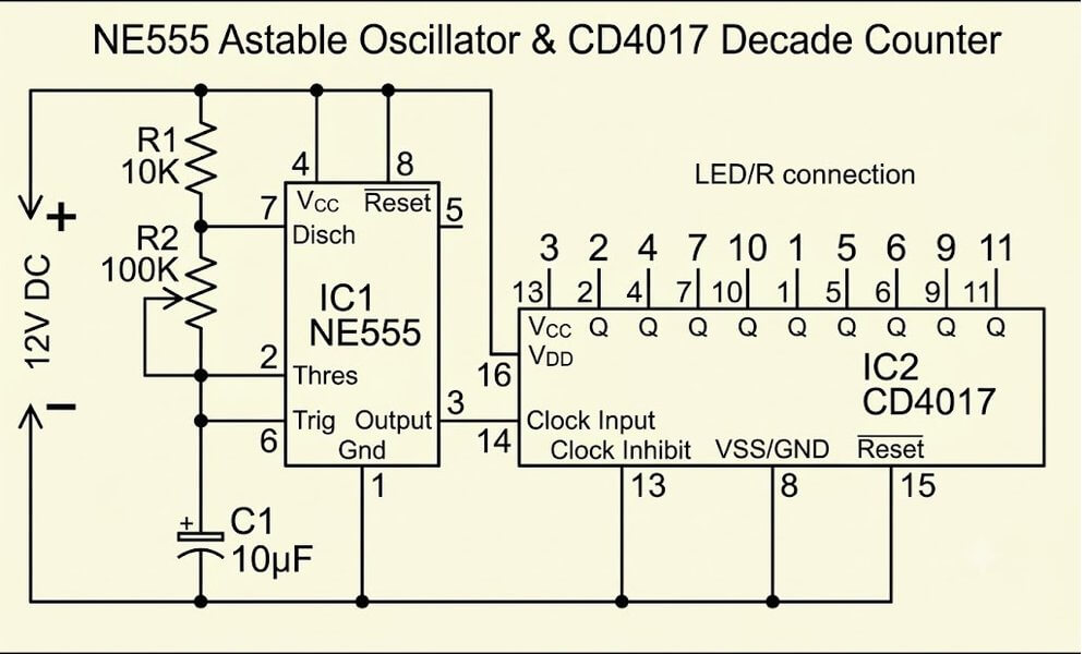
1) Basic 10-LED Chaser Circuit (555 + CD4017)
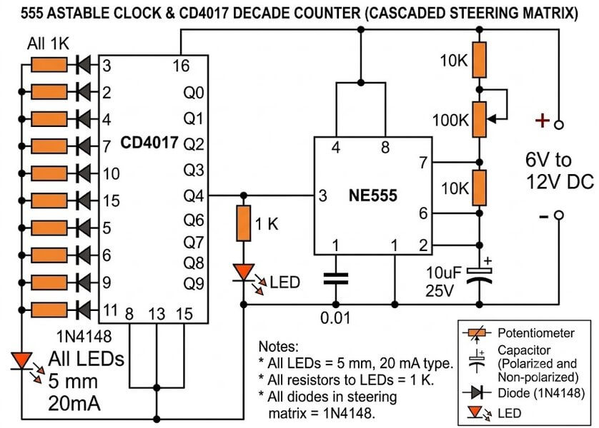
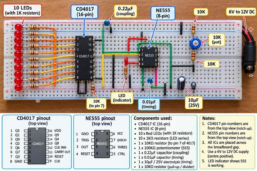
How it works: This is the ultimate beginner-friendly running light project. It uses a standard 555 timer IC wired as a clock oscillator, sending steady pulses directly into a CD4017 decade counter IC. The 4017 takes those clock ticks and turns its 10 output pins ON one by one in a clean, continuous loop.
Main features: You get a smooth 10-LED chasing sequence that works anywhere from 6V to 12V DC. Speeds are fully adjustable—just turn the 100k speed control pot to speed up or slow down the running effect. LEARN MORE...
2) 18-LED Cascaded Chaser Circuit (Dual CD4017)
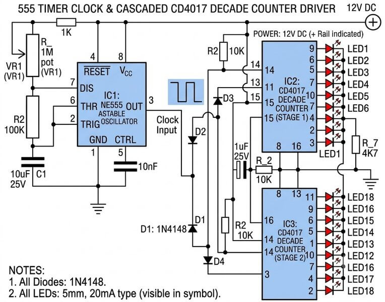
How it works: A single CD4017 chip can only handle 10 steps, but when you need a longer running line, you can link two 4017 ICs together.
The 555 timer provides the main clock heartbeat. Once the first 4017 finishes counting through its pins, it passes the duty over to the second IC.
Main features: Uses a few steering diodes hooked between the two counter chips to handle the handover logic seamlessly.
This lets you run 18 LEDs sequentially without needing microcontrollers or writing software code.
3) 100 to 200 LED Forward-Reverse Chaser (Diwali & Christmas Decorative Lights)
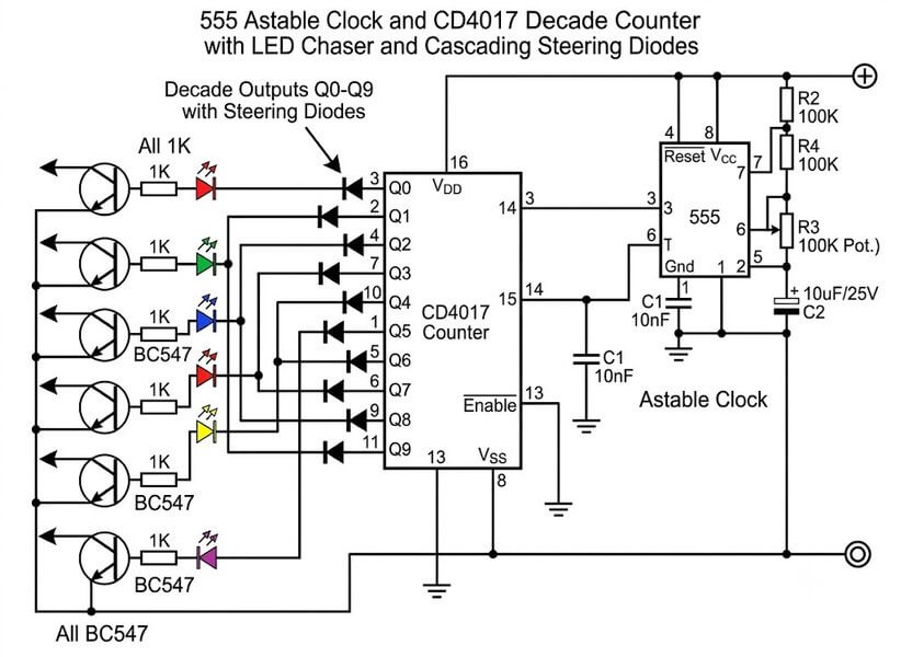
How it works: Basic chasers are fun on a breadboard, but festive lighting for Diwali or Christmas demands a lot more power and bigger arrays. This circuit expands standard sequencing by adding heavy-duty transistor driver stages.
Main features: Instead of just cycling in one boring direction, the lights travel forward to the end and then reverse back toward the start. Depending on the power supply and transistor setup, you can hook up massive strings from 100 up to 200 LEDs. LEARN MORE...
4) Dual-Mode LED Chaser with Flashing Blinker Effect
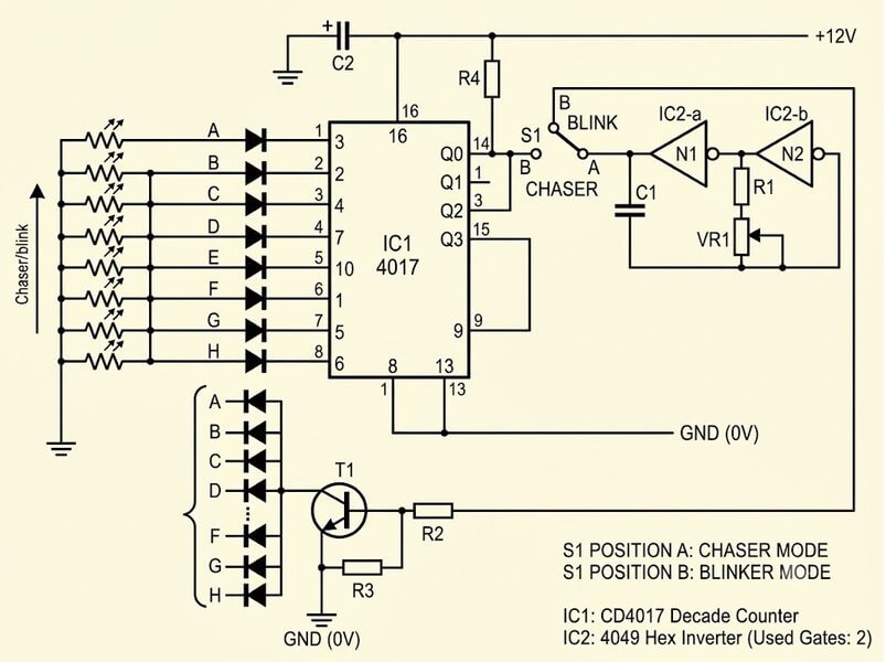
How it works: Designed to answer a popular reader request: having one circuit that can chase and flash. It combines together a standard running sequencer with a master bypass line connected to a selector switch.
Main features: Flip the toggle switch to mode one and the LEDs run sequentially one after another. Flip it to mode two, and the chasing stops while all LEDs begin flashing together in a full-bank strobe effect. LEARN MORE...
5) Center-Out Outward Chasing LED Circuit
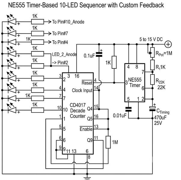
How it works: Most chaser designs move left to right, but this setup changes the visual routine entirely.
By cross-wiring output pairs from the middle of the LED strip outward, the lighting starts right at the center.
Main features: As clock pulses arrive, the light bursts symmetrically outward toward both ends at the same time.
It gives a striking spreading-light effect that looks great on custom display signs and automotive panels. LEARN MORE...
6) KITT Scanner Knight Rider LED Chaser
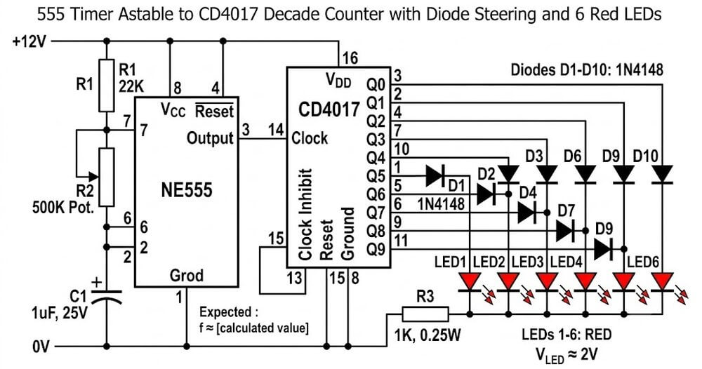
How it works: Inspired by the iconic scanning red light on the front of the KITT car from Knight Rider. It pairs the trusty 555 timer and 4017 decade counter with a simple matrix of 1N4148 signal diodes.
Main features: The diode matrix routes output pulses so a group of 6 LEDs lights up back and forth in a smooth, continuous scanning motion.
No programming needed...just pure hardware logic. LEARN MORE...
7) Slow Adjustable Fading LED Chaser Circuit
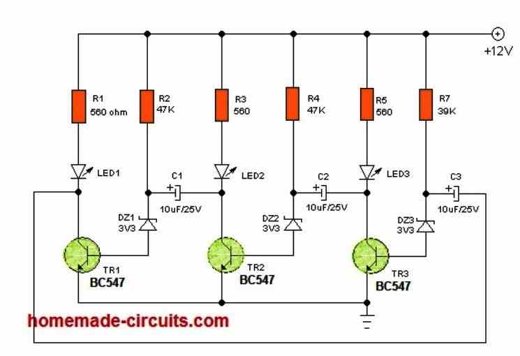
How it works: Standard digital chasers snap LEDs ON and OFF instantly. If you want a softer, more elegant look, this circuit places discrete BJT transistor stages and charging capacitors at each LED output.
Main features: As each output triggers, the capacitor charges and slowly fades the LED up, then slowly discharges to fade it down.
This creates a smooth, gentle lighting transition ideal for mood and decorative displays. LEARN MORE...
8) 8-Bit Shift Register LED Chaser (74C164 + 4011)
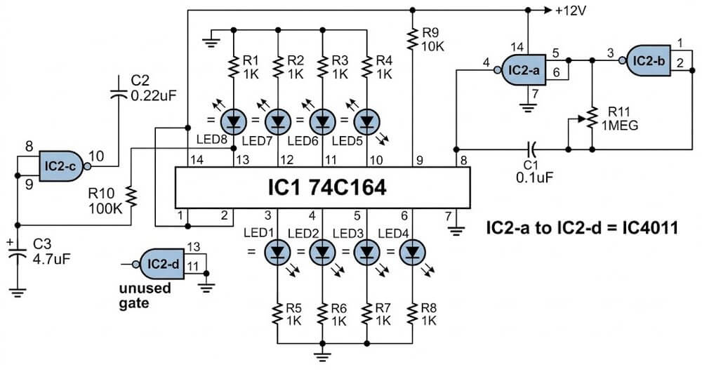
How it works: An alternative way to build a running light display without using a 4017 counter. It uses a 74C164 8-bit shift register IC paired with a 4011 quad CMOS NAND gate IC acting as the clock pulse generator.
Main features: Shifts a bit across an 8-LED sequence continuously.
An RC network on the reset pin makes sure the board clears its memory and restarts the cycle cleanly every time it hits the 8th step. LEARN MORE...
9) Dual 74LS164 Center-Meeting LED Bar Chaser
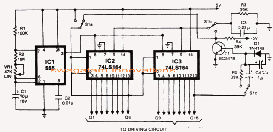
How it works: An advanced shift-register circuit built with two 74LS164 ICs and a 555 clock timebase. The logic is wired so that bits shift inward from opposite ends of the display board.
Main features: Two glowing light points start on the outer edges, travel toward each other, and meet right in the middle.
A quick transistor reset stage then clears the line so the cycle can start over. LEARN MORE...
10) 16-Step Bidirectional Chaser Circuit (IC 40193 + IC 4514)
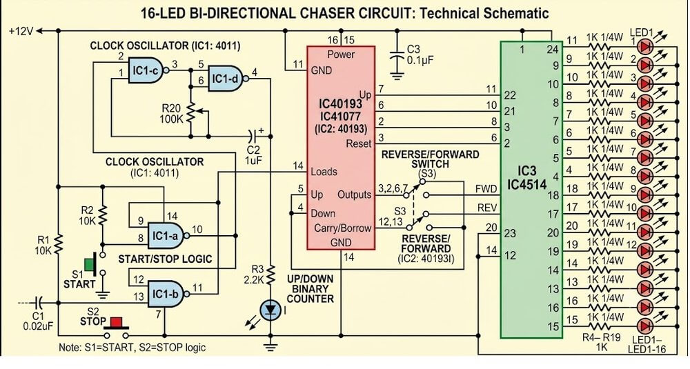
How it works: For high-step sequencing without microcontrollers, this setup replaces the 4017 with a 40193 up/down binary counter and a 4514 1-of-16 decoder IC.
Main features: A simple NAND gate latch handles direction changes automatically.
You get a full 16-step forward-and-reverse running sequence with total stability and no programming required. LEARN MORE...
Common Problems in LED Chaser Circuits
Sometimes an LED chaser circuit may not work properly after building it. So following are some common problems and the things you can check.
Fault#1: LEDs are not glowing
First check the power supply and make sure the positive and negative connections are correct. Also check the IC pin connections, LED polarity and any loose wires on the circuit.
Fault#2: All LEDs are glowing together
Check the wiring of the IC outputs and make sure the LEDs are connected according to the circuit diagram. A wrong connection can stop the normal chasing action.
Fault#3: LEDs are chasing too fast or too slow
In circuits using an IC 555 timer, the chasing speed depends on the timing resistor and capacitor values. Check these components and adjust them according to the circuit design.
Fault#4: Some LEDs are not glowing
Check the polarity of those LEDs and inspect their connections. Also check whether the required current limiting resistors are fitted correctly.
Fault# 5: The circuit works for some time and then stops
Check the power supply voltage, loose connections and any components that may be overheating. If transistors are used to drive many LEDs, you make sure they are not being overloaded.
Always disconnect the power before checking or changing any wiring. If the circuit operates from mains electricity, do not touch the circuit while it is connected to the supply.
How you can Add more Number of LEDs in a Chaser Circuit?
Sometimes you may want to connect more LEDs to a chaser circuit than what is shown in the diagram. This is possible in some circuits but the method will depend on how the circuit is designed. For example the IC 4017 has 10 decoded outputs, so it can control 10 chasing steps in its normal arrangement.
Now if we want more steps then we may need to add another IC 4017 and connect it nicely with the first IC. So just connecting more LEDs to the same output will not increase the number of chasing steps.
In circuits which uses shift register ICs we can also add more ICs to increase the number of LEDs in the sequence. But the extra connections you must do correctly for the circuit to work as expected.
We must also check the power supply current. When more LEDs are added then circuit may need more current. If the IC output cannot supply the required amount of current, we may have to use extra transistors to drive the LEDs...
So before you add more LEDs, first of all you have to check the circuit diagram and the IC output limits, do not simply connect extra LEDs without checking the current, or else the IC or other components may get damaged.
Which is your Favorite LED Chaser?
So guys, that's it! These were a handful of interesting and cool LED chaser circuit designs and compilation, which provides you with varied options of creating your own LED chasing effect without depending on any microcontroller ICs. So which one did you like? Do let us know in the comment section, and if you have any issues with the circuits, do not hesitate to ask them through your comments.

Questions & Answers
sir,do u have single time LED Chaser after stop.and glow single LED >?
Bhavin, I could not understand your requirement….please explain it elaborately…
sir,need circuit diagram one time LED chasing after stop chasing
Bhavin, if you want the LEDs to illuminate sequentially only once, and then stop with one LED lit up, you can try the following circuit, see how pin#13 and pin#15 are configured:
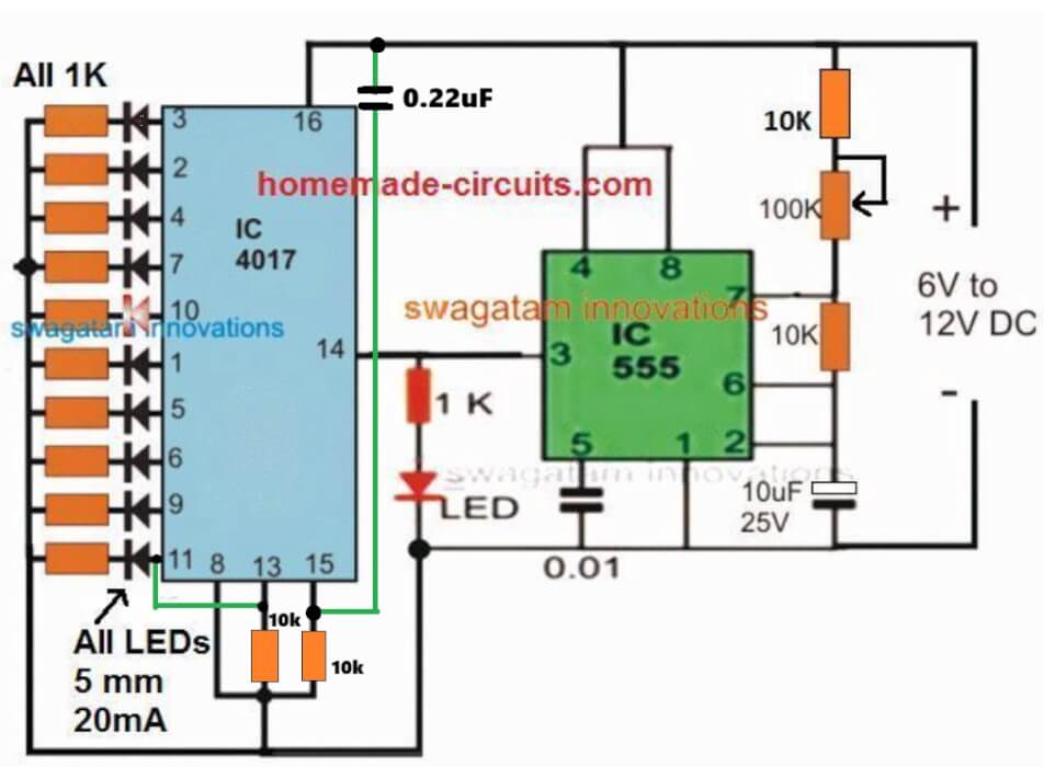
in this diagram last 11 no pin glow and 14 no pin blinking
Yes, that will happen, because one full chasing sequencing stops at the last pin11, as you wanted. You can remove pin14 LED, if you don’t want it…
I want to make a round LED chaser circuit. It will be placed around the doorbell switch
You can remove LEDs on pin11 and pin14, if you do not want them…
no of led increase 18 then what will circuit diagram
use the 74LS164 based circuit.in this solution how many led operate in single ic
8 LEDs on one IC:
https://www.homemade-circuits.com/led-chaser-circuit-using-ic-74ls164-leds-illuminate-in-bar-mode-then-shut-off-together-or-one-by-one/
please share circuit diagram
It is given under 4) LED Scanner Circuit Mustang Type, in the above article…
sir,planning change in circuit.LED chase once after all LED are glow.please share circuit diagram
4017 circuit cannot easily modified for LEDs to glow all together after one chase, for that you may have to use the 74LS164 based circuit explained in the above article…
You can try this:
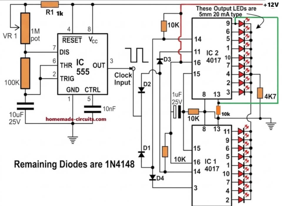
love your 18 chaser light circuit only problem it needs to run on 1.2v dc i want
to use on my solar light i have in my yard that failed. it is a 8 pin single ic that
runs all 18 leds. so your circuit peaked my interest. the original 8 pin ic i cant
see any numbers on it to maybe replace it. so im looking at your circuit with
the 555 and a pair of 4017. any thoughts on what to do?
gary
I am glad you found the circuit interesting, however the IC 4017 and 555 cannot work with voltages below 3V, so 1.2V seems too low for them to operate correctly.
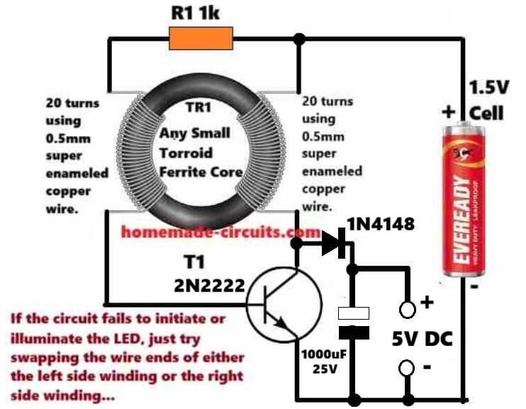
You caan do one thing, boost the 1.2V to maybe 5V and see if the 18 LED circuit works or not.
For the 555 IC please replace it with IC 7555 or LMC555 versions.
For bosting 1.2V to 5V, you can try the following circuit:
Hi Swagatam,
First, thanks for all your efforts.
I have doubt, may be a silly one. In the 18 LED light chaser circuit, how long can I expect the circuit to function efficiently, that is without the battery getting heated or the LEDs getting burnt out. Is it safe to use the same circuit with the mentioned components as I would like to build it for a school project?
Thanks in advance.
Thanks Uma,
There’s no way the circuit can degrade or LEDs burn as long as the DC supply is as per the design specifications…It can keep on working efficiently practically forever..
Yes, it is 100% safe to use the design as exactly shown in the diagram with the indicated supply voltage DC.
You can surely build it for your school project, and let me know if you have any issues with the working of the circuit..
I was hoping to see the dual 4017 knight rider circuit in action, but the link did nothing. Do you have a video of the fading effect also?
Thanks.
which link are you referring to??
Hi
Swagatam finally got to work on the modified chaser circuit found a error on my side the leds flash now after they go through a sequence then latch then the whole array flash a couple of times but they won’t reset just stay static as if the tip122 is keeping them lit and won’t reset if I disconnect the 1uf cap at pin 9 of the 4017 the led will reset but not flash connecting this cap back the leds will flash but not reset
would you have any ideas
regards
Thank you Sparks, glad to know the LEDs are doing are sequencing and flashing as required.
It seems like the capacitor is leaking current to pin#13, that is why it is getting permanently latched.
Please replace the pin#9 capacitor with a 1uF non-polar capacitor, and the associated 100k with a 1M.
And now check the difference.
Hi swagatam
Thanks will let you know how I get on
regards
Sure Sparks, no problems!
Hi Swagatam
The lights do not flash after the last count and do not reset when I connect the supply the 4017 Counts but will not flash or reset eg LEDs will stay illuminated
regards
Thanks Sparks, please do the following modifications:
please connect pin#15 to ground through a 10k resistor, and connect a 0.1uF between the positive supply and pin#15, this will ensure the sequencing always starts from pin#3 onwards whenever the circuit is powered ON..
Use a non-polar capacitor 1uF for the pin#9 of 4017.
Disconnect the base of TIP122 from the collector of the BC547.
Now check how the LEDs respond. Tis will confirm the basic work of the circuit as per the following concept:
https://www.homemade-circuits.com/sequential-bar-graph-turn-light/
Please let me know the results…
hi Swagatam
I have already taken the bc547 emitter to pin 1 but what is strange is that it will start sequencing but for some reason will not reset and will not flash at the end of the cycle it works ok using the original circuit but I am having problems with the modified circuit to get it working as it should
reqards
Hi Sparks,
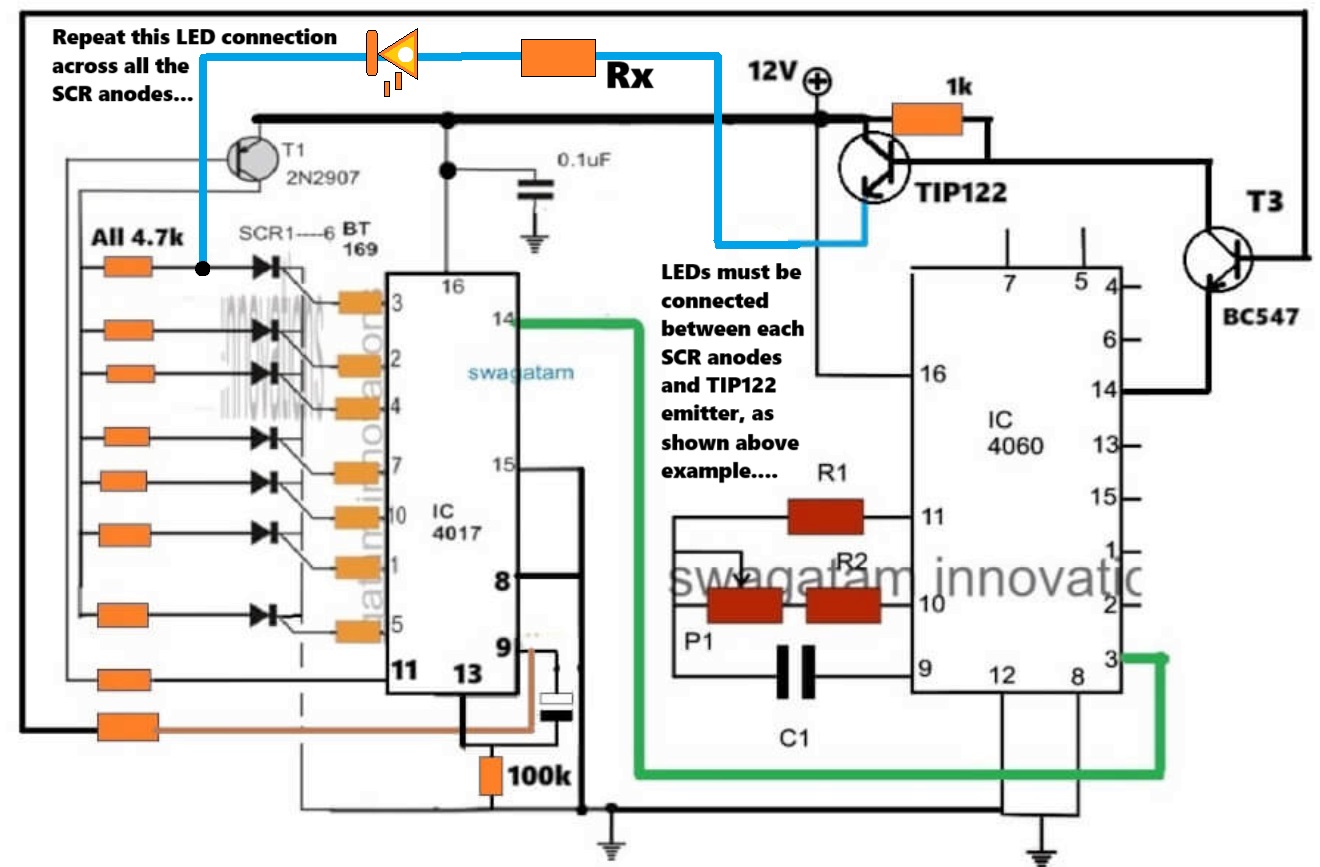
You said that the 4017 circuit stage works correctly and the LEDs illuminate sequentially and also reset normally to repeat the process when it is tested as a standalone circuit. So can you please tell me in what situation does this normal working stops, meaning with which circuit connection does this normal functioning gets disturbed and stops?
hi swagatam
thank you for your quick reply if I leave the emitter open and say connect the led to the 2n2907 collector and to to scr anode the led will be lit and reset and.start the sequence but when I connect it to the tip122 emitter the led will be lit (but not reset or flash the leds )
reqards
sparks
Hi Sparks,
please connect the emitter of the BC547 with pin#1 of IC 4060 to slow down the flashing effect.
The scrs should turn off once the 4017 sequence reaches pin#11. Because at pin#11 2N2907 turns off so there’s no holding current for the SCRs, and since the LEDs are flashing that means these would also cut off current at one instant, which would mean all SCRs latch breaking off due to the complete absence of anode/cathode current and gate current, so at this moment the SCRs would turn off.
Please let me know.
Hi swagatam
A while back you did me modified circuit of.the sequential led array light circuit (that worked ) Then you designed so all the led I am using all flashed at once then reset but I have build it and cannot get it to work you said connect load to Tip122 and anode on scr but the lights stay on plus they no ref to ground
the transistors Tip122 and 2n2907 are both at +voltage
hope you can help
reqards
hope
Hi Sparks,

Yes, I think you are referring to the following circuit idea.
We will have to check and diagnose the circuit step wise.
Initially can you please tell me how the LEDs respond without the TIP122 emitter connected (open)?
BUEN DIA Y CORDIAL SALUDO
DESOHACER UN LETRERO LUMINOSO CON MAS DE 100 LEDS Y ME GUSTARIA CONOCER ESQUEMAS QUE ME PERMITAN ESTO USANDO POCOS ELEMENTOS, TALES COMO:
LEDS
RESISTENCIAS
CAPACITORES
TRANSISTORES
OTRS ELEMENTOS QUE CONSIDEREN INDISPENSALES
Sure, you can try the following circuit design. You can put 4 LEDs in series on each transistor collector arm, adjusting the series resistor value accordingly:
Hi Swagatam, I built the outward chasing LED circuit No:9 by connecting all the parts as shown in your diagram. But my circuit is not working. Capacitor value is shown as 470uF 25V. Is it correct? Can you please assure me that there is no error in the circuit diagram?
Hi Mahesh,
There’s no error in the outward LED chaser circuit configuration, except the IC 555 part values. Please change them to the following values. Replace the 1M pot with 100k pot, 22k resistor with 100k resistor, and 470uF capacitor with a 10uF/25V capacitor. Also, please replace the 555 pin#3 1K resistor with a 10k resistor.
Goodmornig Sir. In the Knight Rider Chaser schematic it mentions 10x1n4008 diodes but only 8 of them are visible. Maybe they go on outputs d1 and 3 of the 4017?
Thanks
Good Evening Rosario,
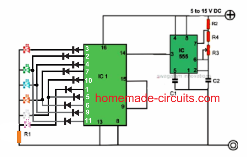
I think the diodes needs to be configured in the following way, if 10 diodes are used:
Hi Swagatam,
In the circuit 16 LED Reverse/Forward Chaser Circuit, if I wanted to use only 14 LED, omitting the last 2, would the circuit continue to function normally?Best Regards.
Nélio.
Hi Nelio,
Yes, if you do not use the last two inputs the circuit should still work normally, according to me.
But since this circuit is not designed by me, I am not entirely sure about its functioning and whether it will successfully work or not, and also I am not well-versed with those ICs.
In your circuit No. 6 – 18 Led chaser circuit If I want to use 3 mm Led
then what changes should I Do ?
No need to change anything in the design, you can use the same circuit design without any changes….
Hi Swagatam,
I have had a look through the prior projects and experiments and could not find a suitably matched project for my needs.
I need to build a circuit that makes 3 or 4 LEDs “breathe” – fade in/ fade out over 2 to 5 seconds. There is a FADE IN/OUT Arduino project in the library but I do want to incorporate Arduino for this setup. I read about using 2 NE555s set slightly out of phase and the pulsing would be equivalent to the beat frequency of the output. The article lost me when it was suggesting XORing the output to the LEDs. Does this make sense to you? How would you do this? Or would you do it differently?
Thanks
Thank you Michael,
Did you check the following article?
https://www.homemade-circuits.com/alternate-onoff-led-fader-circuit/
I think this circuit should be able to fulfill your requirement.
A 5 seconds timer can be added through additional BJT circuit stage.
Please let me know if there’s any specific thing missing in the design.
Alternatively, a single 4093 IC could be also used to get all the required feature from a single chip.
Thanks for this. It’s virtually perfect as is. Any ideas how to make the LEDs brighter. It looks like the highest voltage through them is around 5v. Do you think I could safely bump the input to 19v? What is the BJT circuit?
Cheers
Sure, the LED brightness can be adjusted by adjusting the values of the R6 and R7 resistors.
The IC can work with up to 32 V, so 19 V can never be an issue. Just make sure the voltage rating of C1 and C2 capacitors are at least 1.5 times of 19V or higher. The R6, R7 must be appropriately calculated so that the current does not exceed their max specifications.
The transistors T1 and T2 are the BJTs, and form the BJT circuit.
Hello, Swagatam!
First, THANK YOU for having this website! It’s very generous to do this 🙂
I’m very interested in Circuit #1 and Circuit #5, because those look like something I can actually do and my goal is that I want something I can fit into a sort of “shadowbox greeting card” to be mailed to people.
My question is:
Since I’m looking at either the TLC551 or the LMC555, which as far as I can tell operate a 1V and 1.5V respectively, which values do I need to recalculate to run off of a 3V battery? Or is that not even do-able? I can go up to 6V, because I’ll be using CR2032 button cell(s) and minimal holders.
I’ve been looking, and asking, for the answer of how to go from a 5V-NE555, to a 1V or 1.5V CMOS-555 for three months – no exaggeration! -, but I still have no idea at all what values I need to recalculate to adjust the circuit from the NE555 to the CMOS low-power 555 or 551 IC.
If you could tell me what to recalculate, that would be a huge kindness! Not even do the calculations, but only tell me which things need to be recalculated, would be a big help!Even if I still need 6V but maybe only need to add a resistor to not “blow out” the CMOS timer, if you could tell me that, it would be a major kindness to me!
Thank you!
Hi Kris,
Thank you so much for liking this website, glad you found it useful.
If you check the datasheet of the cmos 555 ic it shows a formula for calculating the operating frequency which does take the supply voltage into account.
https://www.homemade-circuits.com/cmos-ic-lmc555-datasheet-works-with-1-5-v-supply/
That means regardless of the supply voltage the resistor capacitor values can remain the same.
So you can feel free to use the same circuit configuration which are shown in the above article for your specificapplication.
I think a 3V battery supply would be more appropriate instead of a 1.5V, as it would allow sufficient voltage margin for optimal illumination of the LEDs.
Please let me know if you have any further questions or doubts, I will be most happy to solve them for you.