The article illustrates a simple yet innovative, fancy car turn signal light circuit which produces a rising bar graph sequence effect when switched ON.
The circuit idea was requested by Mr. +Bruce Lowry. I have explained more.
Technical Specifications
I am after a circuit design similar to the LED Bar Graph circuit that is found on this site/blog.
What I want to develop is a front turn signal sequential flasher that illuminates and holds the lights from top to bottom and then cycles them again and again until the turn signal is turned off.
I need to drive exactly 12 Amber LED's that drop 1.8 volts per LED. The LED's are laid out from top to bottom as such.
- 1 (number of LED's)
- 1(number of LED's)
- 1(number of LED's)
- 2(number of LED's)
- 3(number of LED's)
- 4(number of LED's)
I would like to illuminate the first one at the top and hold and then move on to the second one down and so forth until all 6 rows which consist of 12 total LED's are illuminated and then start the sequence over.
Variable resistors should be included so that the clock frequency can be altered. This will allow me speed up or slow down the illumination and hold of the LED's.
Plus if there is a variance in the driver side circuit and the passenger side I could use the adjustability to "syncronize" the working rates of both sides. (turning on the hazard flashers to observe both sides being enabled and sequencing would be a good way to visually check this)
In the connector to the front turn signals I am working with three connections.
Top pin is 12 volts constant when running lights are turned on (oh, just a thought- It would be nice to use the entire string of LED's as running lights as well) Middle Pin is zero volts (GROUND) and lower pin is 0-12 volts when the turn signal is activated.
I need a working circuit that will handle automotive voltages that are not always 12 volts in practice , but can range up to 14 or so volts in actual real world use.
A complete circuit diagram would be helpful. Including resistor values for driving the different multiples of LED's and if each LED would have its own resistor or just run them in series with one resistor.
Audio/Video Representation
The Design
The above circuit can be built using two different types of circuit configurations. One which uses the IC 4017, and the other through the IC 74LS164. Here we'll discuss the one which uses the IC 4017.
As shown in the first circuit diagram, the entire design is wired around the IC 4017.
We know that the IC 4017 which is a johnsons divide by 10 decade counter/divider chip produces sequencing high logic pulses on its outputs in response to clocks applied on its pin#14.
In response to each high pulse on pin#14, a high logic shifts from one output to the next in the following pin-out order: 3-2-4-7-10-1-5-6-9-11.
Thus all the 10 outputs become high sequentially until the last pin#11 becomes high after which the sequence returns to pin#3 so that the cycle can repeat yet again.
The cycle keeps repeating as long as the clock pulses are sustained at its pin#14.
However the sequencing pattern does not keep the outputs illuminated while shifting. The outputs become high and then become low again as the sequence shifts from one pin out to the other.
It means at any instant only one output is high during the sequencing process.
If we connect 10 LEDs at the above 10 outputs of the IC 4017, it would provide an impression of a single LED chasing effect, however since for the present car turn signal application we want a bar graph kind of appearance we would want the LEDs to stay and hold their illumination as the sequence proceeds from the start to the finish pin-outs.
To implement this "hold" feature we need to introduce a latching feature with the given outputs.
This can be simply done with the use of SCRs, because as per the characteristics SCRs latch their MT1, MT2 leads if the supply is a DC. Therefore it perfectly suits our application.
By connecting SCRs at the first 6 outputs of the IC we can simply implement the bar graph kind of feature such that the LeDs hold and stay illuminated until the complete is completed.
Pin#1 provides the last sequencing output after which the IC should shut down all the LEDs and begin the procedure all over again.
For actuating the above action, the transistor T1 stage in introduced at the next pin#5, which instantly inhibits the supply voltage to the SCrs so that all of them shutdown.
Pin#6 is tied to the reset pin#15 of the IC which makes sure the sequence gets back to pin#3 as soon as the LEDs shut OFF, enabling the next cycle to commence.
Circuit Diagram
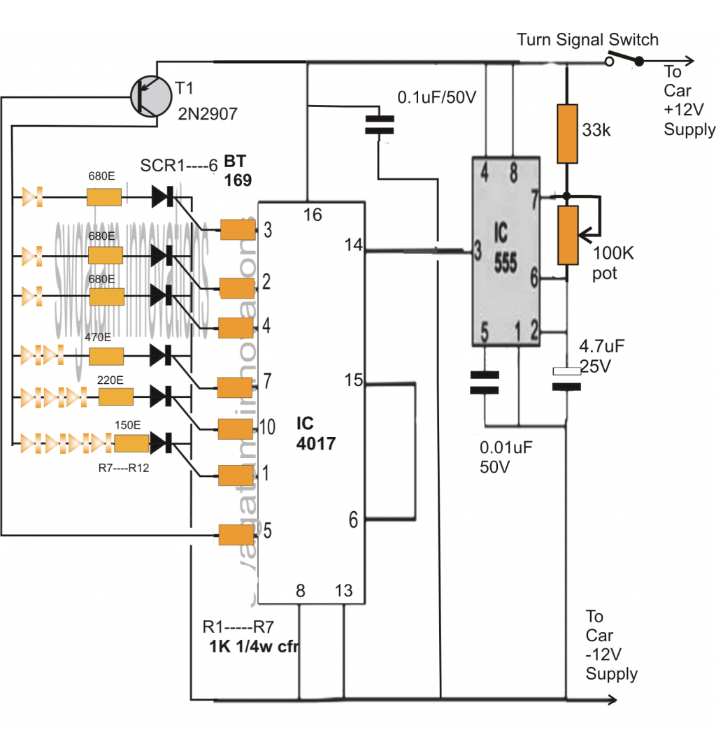
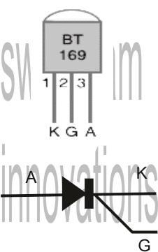
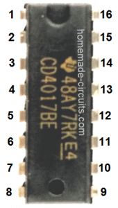
As rightly expressed by Mr. Bruce, the above circuit will not function properly under a fluctuating DC which would be normally available across the existing turn signal light outputs due to switching of the flasher relay.
Adding a Delay Timer
However the above circuit can be simply modified by adding a small time delay circuit, which would hold the current and keep the circuit functioning switched ON by supplying the required amount of power during the absence of supply from the flasher relay.
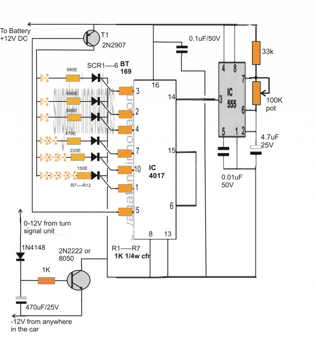
The above sequential car turn signal light circuit was successfully built and tested by Mr.Bruce Lowry.
The wonderful results can be witnessed in the following video. Please refer to the comments to learn regarding the whole process.
With an adjustable rate of flash added, the circuit now looks much enhanced. Courtesy: Mr.Bruce Lowry.
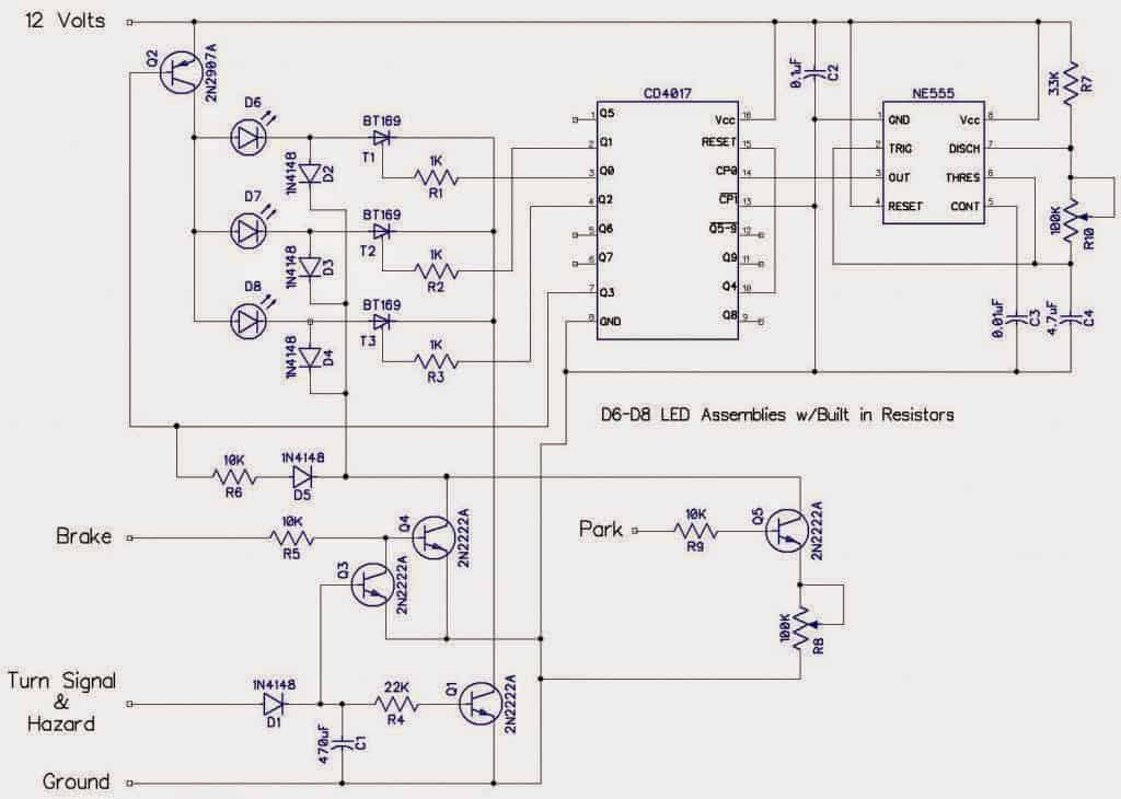
The above design was further modified by Mr. Jason in order to implement additional specific actions such as making the LEDs stay solid when the brakes are applied, but also making sure that the LEDs stayed in the flashing/running mode in case both: the turn signal and the brakes were switched ON together or simultaneously.
Modifying Further
The modified design which is attached below has an additional feature wherein the LEDs could also be used as park lights thereby making the above circuit a 3 in 1 unit:
Here's the complete design drawn by Mr. Jason for your viewing pleasure:


Questions & Answers
Hello Swagatam,
Looks you are doing great job for the community.
Can you help me with a circuit diagram for Motorcycle Indicators Flowing Turn White/Red/Amber. like this Link : https://www.ebay.com/itm/266706573438
I would like to use this to create circuit board and use it.
Thanks
Thank you Shishir,
Can you please tell me how the LEDs are supposed to illuminate? Once I know this I can try to figure out the design…
Hello Swagatam,
Thank you for your reply.
Here is what I am looking for
1. Two front indicator should glow white and amber with flowing pattern.
2. When turning on indicator the white DRL should turn off and amber should glow in flowing mode.
3. Once turned off DRL should glow and amber should turn off.
4. Same with back turn signal with re and amber.
Here is the youtube link
youtu.be/BYvmQ7QrZfc
Thank you
Thank you Shishir,
The LED running pattern appears to be having more than two sequences which looks difficult to implement using a discrete circuit, so it may not be possible for me to design this multiple-pattern LED illumination.
However, the 4 points that you have mentioned above is possible, assuming the “flowing pattern” is just a simple running LED light pattern, which can either be a “dot” mode or “bar” mode.
Let me know your thoughts on this.
I like tis circuit. I would like to be able to connect to a 4 wire hitch like the LED Bar strips. Brake and turn signal are combined. There is no constant 12v supply. I haven’t found a schematic that explains how to make the sequential turn and brake work separately.
Regards,
Randy
I will have to see how the 4 wire LED is designed to work, only then I would be able to suggest.
If there’s no constant supply from a 12V battery then the above circuits won’t work.
Hi Swagatam and thank you for the circuit you have shared.
I Must say, mine works mostly well, although the one issue i have, when connecting the indicator line to 12v (re Diagram 1) all of my leds light up, except for the first one in the sequence. But if i hold the indicator wire to 12 input, when it finishes the first run through sequence, it will begin the 2nd one and light up all the leds including the first one this time. I am unsure what could be causing this behavior.
The first led in the sequence is connected through the collector on pin 3 on the 4017 ic (marked as output 0)
Any idea why it would skip the first led during the initial sequence when 12 is applied, but then light all led on the 2nd sequence?
Thanks
Thank you Zap123, it could be probably due to some kind of spike or instability which might causing the erratic behavior.
You can try putting a 100uF capacitor across supply pins of both the ICs, and additionally connect the IC 555 pin3 with the 4017 pin14 through a series 100k resistor, and connect a 0.22uF capacitor between pin14 and ground.
I see what you are trying to say. I am yet to give this a go, i just wanted to clarify, i am putting separate 100uf caps for pin 16 on the 4017, and then 2 separate caps for pin 4 and pin 8 on the 555, only pin 8 on the 555?
Assuming, I only need to put the cap on pins 16 and 8, would I be able to get away with having 1 200uf cap for both pins 16 and pin 4, or will this not work correctly. Trying to think of the most efficient way for when I design my rev 2 board.
Thanks 🙂
Just one 100uF capacitor each across the supply terminals of the two ICs will be enough. Let’s hope this helps to solve the issue!
Hi Swagatam
This seems to have corrected the activity in some cases, although now that it will start from the first LED on initial power supply, it seems as though, when power is disconnected and reconnected in the space of less than 3 to 5 seconds, the circuit will hold charge somwhere, and then resume the sequence from where the power was disconnected. (when resuming the sequence, it will not light the previous led’s until the next run through the sequence) The best way i can explain it would be to show below how it will run through the sequence
(x) Resembles Light on
(o) Resembles Light off
-o-o-o-o-o-o-o-o-o-o-
-x-o-o-o-o-o-o-o-o-o-
-x-x-o-o-o-o-o-o-o-o-
-x-x-x-o-o-o-o-o-o-o-
-x-x-x-x-o-o-o-o-o-o-
——–Power Cut Less than 3 Seconds——–
-o-o-o-o-x-o-o-o-o-o-
-o-o-o-o-x-x-o-o-o-o-
-o-o-o-o-x-x-x-o-o-o-
-o-o-o-o-x-x-x-x-o-o-
-o-o-o-o-x-x-x-x-x-o-
-o-o-o-o-x-x-x-x-x-x-
-o-o-o-o-o-o-o-o-o-o-
-x-o-o-o-o-o-o-o-o-o-
-x-x-o-o-o-o-o-o-o-o-
-x-x-x-o-o-o-o-o-o-o-
-x-x-x-x-o-o-o-o-o-o-
I feel like the current might be held in the 0.1uf capacitor that connects the positive to the neg rail. do you think adding a diode on the positive side would prevent backcharge? I will try this and report back. please let me know if you have any other suggestions
Hi Zapp, that looks very strange, because 4017 do not have “memory.”
You can do one thing….connect the pin#15 to ground through a 10k resistor, and then connect any small value capacitor between positive rail and pin#15..this will reset the IC each time power is switched off and allow the sequence to begin from pin#3
Hi Swagatam
Sorry for taking so long to get back to you. It has taken me some time to free myself to test this fix.
With this being said, after adding the 10k resistor between Gnd and reset, and the 0.1uf cap between vcc and reset. This has tightened up timing in regards to how long I have to wait before restarting the sequence when power is disconnected. As before I’d have to wait between 3 to 5 sec, I now only have to wait 1 sec before it will start the sequence again from the beginning.
I am Baffled as we are supplying voltage to the reset pin as soon as the circuit sees power. So I do not understand why it is still acting this way
Would you happen to have any other ideas? Thanks in advance
No Problem Zapp!
However a 1 second delay with a 0.1uF/10K as the reset network looks strange. Because the 0.1uF should charge within milliseconds and enable the sequencing quickly for the IC. You can reducing the 10K to 1K and check the response again. Nevertheless, it seems there may be something else not right either with the circuit or the IC itself. Will need to be investigated by replacing the IC with a new one perhaps.
Hi swagatam,
I tried the circuit which you suggested. it’z working good in sequential. but here i need a small modification.
if when ever I applied the brake, leds lights up sequentially and stay all lights should ON till I release brake.
but here, when powered to the circuit, sequential effect continues.
can you please help me what changes should I do here.
Thanks in advance…:)
Hi Vamsi, the LEDs will latch and remain ON if the transistor is disabled during power switch ON. So when the brakes are applied it must switch ON the positive supply to the circuit and also simultaneously should apply the positive to the base of T1. This will disable the T1 and allow you to get the required results.
sorry, please correct my previous comment, T1 must be permanently enabled to ensure the LEDs stay switched ON after one chasing sequence. For this use a BC547, connect its collector to T1 base via a 1 k resistor, emitter to ground, and base to brake positive via a 10k resistor. The brake switch must also supply the positive supply to the circuit when it is pressed.
Very good sir….Liked ur project very much. But I want to make on 1w led with 10 channel and with del white light on….When we turn on engine ..DRL of white color is on and when we turn on indicator white is off and sequential turn signal is flashing…..This is one of my dream projects with 1w or 3w LEDs… Please guide if possible
Sirji so humble of you. But I am little novice to electronics. If u can make a video on your YouTube channel on this with drl and sequential turn signals that would be a help to …many headlamp and tail lamp modifiers like me
Thank you Amit, however making a detailed construction video will not be possible at this moment, in future I may surely consider it.
Ok sir, can u just please modify that diagram to the newer one
Please make the circuit which is shown in the second design, once you build it successfully then i’ll explain how to do the next modification.
Glad you liked it.
Please see the second circuit and do the following additions.
Connect a TIP122 transistor in the following manner:
Base to 12V via ignition switch. Connect the base also to the collector of 2N2222 in the second diagram.
Connect the emitter of TIP122 to the ground line.
Connect the DRL between collector of TIP122 and battery positive line
hi my friend… i make this circuit in a board and i put small led with mcr100-8 thyristor. with small led wprk perfect.. but i have 3 watt led im my car with led drivers.. so when i put 12 volt the sequence start but not bright all and in the end only two led turn on.. the sequence work like have tranzistor.. what can i do… please help me..
Hi, which SCR did you use? Please use C106 SCR, and replace the transistor with TIP127
calculate the resistor using this formula:
R = (12 – LED FWD V) / LED Current
Hello Swagatam, i built the project according to the first diagram and would like to connect 3 watt leds , i replaced the Scr’s for the C106 and T1 for the Tip 127. Unfortunately it won’t work when connecting 1 led it works fine but after that it works wrong and some leds are only blinking. Can you maybe help me? Greetings René
Hello Rene, which resistor did you connect in series with each LED?
hello Swagatam, I am using a led driver to drive the leds.
Hi Swagatam, yes that is correct. I still had these laying around, I have now ordered 15ohm. Greetings René
No problem Rene, I hope it works for you perfectly!
Hi Swagatam, I did a test with 20ohm resistors and now it works indeed. Thank you for your help. Greetings René
That is great Rene, I am glad you could solve it, however a 20 ohm is too high for a 3 watt LED at 12 V, and it will cause the LED to glow with a relatively low illumination.
Mr. Swagatam:
I have been involved in electronics since 1965 and take I interest in unique circuits such as the sequential led driver by you and Mr. Jason. I completely understand 99% of the circuit however I am baffled by R6 and D5 as to their function? Another question is how the counter can start at #1 when the 555 timer is running open loop and driving the counter continuously even though no leads light until the turn signal is applied. Seems like the led sequence would start wherever the counter happens to be. Thanks for your sanity check if you get time.
Many thanks for your quick response! My project not only involves a 10 lamp circuit but also includes building the lamp fixtures as well. My truck does not have existing fixtures so that is an additional project by itself. Again many thanks I will share my results.
No problem, I wish you all the best!
Thank you Mr. Ray, you are right, the R6, D5 don’t make sense, however I think they are mistakenly shown in the wrong area. D5 is actually not required but R6 is required and it should be in series with the collector of Q4. R6 value should not be more than 1K
To answer your second question, I don’t think it is important for the 4017 output to reach #1 each time the turn signal is switched ON simply because the sequencing is supposed quite fast….,therefore it can start from anywhere in sequence and keep cycling across the 3 outputs
OK, however I would recommend using individual LEDs and a calculated series resistor with each LED. An LED with driver across each SCR might not be a good idea. Also for 3 watt LEd on each channel, a TIP127 might not work. You might have to use a TIP147 with a large heatsink.
Can someone share PCB look for this circuit?
Hi! Thanks for this project !
Can make this work with about 70 leds?
With other 4017?
Can help me…plz….
Hi, I have not yet investigated how to cascade many 4017 together, if its possible I may research on this and publish it here.
THanks!