In this post I have explained a two op amp IC 741 and LM358 based auto cut off battery charger circuits which are not only accurate with its features but also allows a hassle free and quick setting up of its high/low cut-off threshold limits. High current batteries can e also charged using these circuits.
The idea was requested by Mr. Mamdouh.
Circuit Objectives and Requirements
- As soon as I connect the external power automatically it will disconnect the battery and supply the system, in the meanwhile charging the battery.
- Overcharging protection ( which included in the above design).
- Battery low and full charging indications (which included in the above design).
- Also i don't know what is the formula to help how to determine the voltage required across my battery to charge it with( battery will be extracted of old laptops.total will be 22V with 6 apms at no load)
- Furthermore, I don't know the formula to indicate how long my battery will last, and how to calculate the time if i want a battery to last me two hours.
- Also, the cpu fan will supplied by the system too. It would be great too to add the option of a dimmer, my original plan was to vary between 26-30 v not need much more than that.
Circuit Diagram
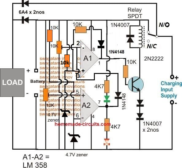
The Design
In all of my previous auto cut off battery charger controller circuits I have used a single opamp for executing the full charge auto cut-off, and have employed a hysteresis resistor for enabling the low level charging switch ON for the connected battery.
However calculating this hysteresis resistor correctly for achieving the precise low level restoration becomes slightly difficult and requires some trial and error effort which can be time consuming.
In the above proposed high current auto cut off low high battery charger controller circuit two opamp comparator are incorporated instead of one which simplifies the set up procedures and relieves the user from the long procedures.
Referring to the figure we can see two opamps configured as comparators for sensing the battery voltage and for the required cut-off operations.
Assuming the battery is s 12V battery, the lower A2 opamp's 10K preset is set such that its output pin#7 becomes high logic when the battery voltage just crosses the 11V mark (lower discharge threshold), while the upper A1 opamp's preset is adjusted such that its output goes high when the battery voltage touches the higher cut off threshold, say at 14.3V.
Therefore at 11V, the A1 output gets positive but due to the presence of the 1N4148 diode this positive stays ineffective and blocked from moving further to the base of the transistor.
The battery continues to charge, until it reaches 14.3V when the upper opamp activates the relay, and stops the charging supply to the battery.
The situation is instantly latched due to the inclusion of the feedback resistors across pin#1 and pin#3 of A1. The relay becomes locked in this position with the supply completely cut off for the battery.
The battery now begins slowly discharging via the connected load until it reaches its lower discharge threshold level at 11V when the A2 output is forced to go negative or zero.
Now the diode at its output becomes forward biased and quickly breaks the latch by grounding the latching feedback signal between the indicated pins of A1.
With this action the relay is instantly deactivated and restored to its initial N/C position and the charging current yet again begins flowing towards the battery.
This auto cut off low high battery charger circuit can be used as a DC UPS circuit also for ensuring a continuous supply for the load regardless of the mains presence or absence and for getting an uninterrupted supply through out its usage.
The input charging supply could be acquired from a regulated power supply such as an LM338 constant current variable constant voltage circuit externally.
How to Set the Presets
- Initially keep the 1k/1N4148 feedback disconnected from the A1 op amp.
- Move the A1 preset slider to ground level, and move the A2 preset slider to the positive level.
- Through a variable power supply, apply 14.2 V which is the full charge level for a 12 V battery across the "Battery" points.
- You will find the relay activating.
- Now slowly move the A1 preset towards the positive side until the relay just deactivates.
- This sets the full charge cut off.
- Now, connect the 1k/1N4148 back so that the A1 latches the relay in that position.
- Now slowly adjust the variable supply towards the lower discharge limit of the battery, you will find the relay continues to remain switched OFF due to the above mentioned feedback response.
- Adjust the power supply down to the lower battery discharge threshold level.
- After this, begin moving the A2 preset towards the ground side, until this turns A2 output to zero which breaks the A1 latch, and switches ON the relay back to the charging mode.
- That's all, the circuit is fully set now, seal the presets in this position.
Answers for other additional questions in the request are as given under:
Formula for calculating full charge cut off limit is:
Battery voltage rating + 20%, for example 20% of 12V is 2.4, so 12 + 2.4 = 14.4V is the full charge cut off voltage for a 12V battery
To know the battery back up time the following formula can be used, which gives you the approximate battery back up time.
Backup = 0.7 (Ah / Load Current)
Another alternative design for making an automatic over/under charge cut-off battery charger circuit using two op amps, can be seen below:
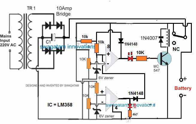
How it Works
Assuming there's no battery connected, the relay contact is at N/C position. Therefore when power is switched ON, the op amp circuit is unable to get powered and stays inactive.
Now, suppose a discharged battery is connected across the indicated point, the op amp circuit gets powered through the battery. Since the battery is at a discharged level, it creates a low potential at (-) input of the upper op amp, which may be less than the (+) pin.
Due to this, the upper op amp output goes high. The transistor and the relay activate, and the relay contacts moves from N/C to N/O. This now connects the battery with the input power supply, and it begins charging.
Once the battery is fully charged, the potential at (-) pin of the upper op amp becomes higher than its (+) input, causing the output pin of the upper op amp to go low. This instantly switches OFF the transistor and the relay.
The battery is now disconnected from the charging supply.
The 1N4148 diode across the (+) and the output of the upper op amp latches so that even if the battery begins dropping it has no effect on the relay condition.
However, suppose the battery is not removed from the charger terminals, and a load is connected to it so that it begins discharging.
When the battery discharges below the desired lower level, the potential at pin (-) of the lower op amp goes lower than its (+) input pin.
This instantly causes the output of the lower op amp to go high, which hits the pin3 of the upper op amp. This instantly breaks the latch, and switches ON the transistor and the relay to initiate the charging process yet again.
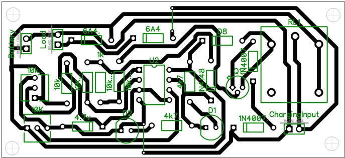
PCB Design
Adding a Current Control Stage
The above two designs can be upgraded with a current control by adding a MOSFET based current control module, as shown below:
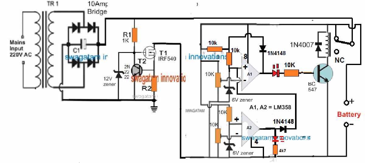
R2 = 0.6 / charging current
Adding a Reverse Polarity Protector
A reverse polarity protection can be included to the above designs by adding a diode in series with the positive terminal of the battery.
Cathode will go the battery positive terminal, and anode to the op amp positive line.
Please make sure connect a 100 Ohm resistor across this diode, otherwise the circuit will not initiate the charging process.
Removing the Relay
In the first auto cut off based battery charger design, it may be possible to eliminate the relay and operate the charging process through solid state transistors, as shown in the following diagram:
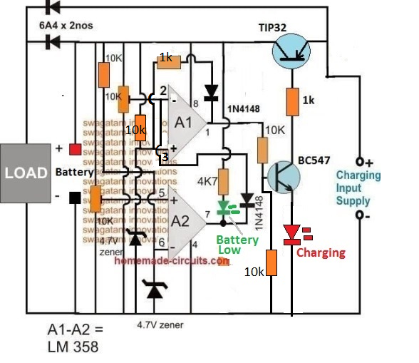
How the Circuit Works
- Let's assume A2 preset is adjusted at 10 V threshold, and A1 preset is adjusted at 14 V threshold.
- Suppose we connect a battery that is discharged at an intermediate stage of 11 V.
- At this voltage pin2 of A1 will be below its pin3 reference potential, as per the setting of the pin5 preset.
- This will cause the output pin1 of A1 to be high, turning ON the transistor BC547 and the TIP32.
- The battery will now start charging via TIP32, until is terminal voltage reaches 14 V.
- At 14 V, as per the setting of the upper preset, pin2 of A1 will go higher than its pin3, causing the output to turn low.
- This will instantly switch OFF the transistors, and stop the charging process.
- The above action will also latch the A1 op amp through the 1k/1N4148 so that even if the battery voltage drops to the SoC level of 13 V, the A1 will continue hold the pin1 output low.
- Next, as the battery begins discharging via an output load, its terminal voltage begins dropping, until it has dropped to 9.9 V.
- At this level, as per the setting of the lower preset, pin5 of A2 will drop below its pin6, causing its output pin7 to turn low.
- This low at pin7 of A2 will pull pin2 of A1 to almost 0 V, such that now pin3 of A1 becomes higher than its pin2.
- This will immediately break the A1 latch, and the output of A1 will once again turn high, enabling the transistor to switch ON and initiate the charging process.
- When the battery reaches 14 V, the process will repeat the cycle yet again
How Set the Presets
Initially keep the wiper arm of A1 preset to the ground level, and keep the wiper arm of the A2 preset at the positive supply level.
Take a variable power supply, adjust its voltage to the full charge level of the battery and connect the supply to the circuit from the "battery side" (not from the emitter side of TIP32).
You will see that the RED LED has illuminated.
Now, slowly adjust the A1 preset until the RED LED just shuts off.
The full charge cut off is now set.
After this, decrease the power supply voltage to a point which corresponds to the low discharged level of the battery at which the charging needs to be restarted.
Now adjust the A2 preset slowly until the Green LED and the RED LED both illuminate together.
Your low battery recharge level is now set.
That's all, now you can try testing the circuit on a real discharged battery, but this time make sure to connect the charging supply from the emitter side of TIP32.
Single Op amp Automatic Battery Charger Circuit
Automatic battery chargers just aren't economical, but the protection they provide from overcharging and potential battery degradation is extremely appealing.
The circuit illustrated here is meant to be a low-cost replacement to commercially available fully automated chargers.
The concept is to pick a basic battery charger and install an add-on module that will automatically check the condition of the battery and turn off the charge current as soon as the battery gets fully charged.
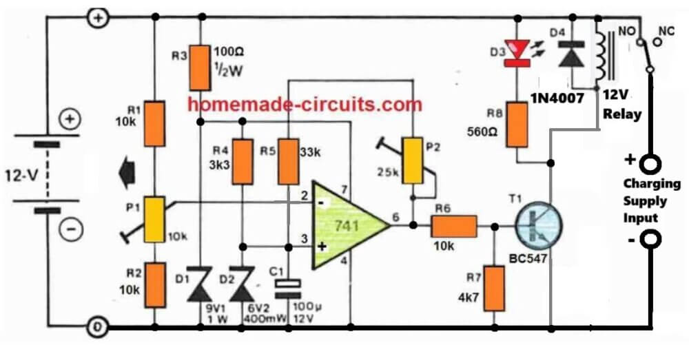
How it Works
The circuit is simply made up of a comparator that checks the battery voltage in relation to a preset reference value.
When the battery voltage surpasses a certain peak value, a relay is turned OFF, causing the charge current to be terminated. When the battery voltage declines below a certain specified lower limit, the relay activates, allowing the charge current to flow again.
A 741 op-amp serves as the comparator. The op-amp's supply voltage is stabilized by R3 and D1, thus it is immune to fluctuations in battery voltage.
The reference voltage, that is supplied to the op amp's non-inverting input through R4 and D2, is generated through this stabilized supply.
The reference voltage is compared with the battery charge voltage, via the resistive divider.
As the battery charges, the voltage at the inverting input of the op-amp finally becomes higher than that on the non-inverting input, causing the output of the op-amp to go low, switching off T1 and T2.
This causes the normally closed contact of the relay to open, cutting off the input charge current to the battery.
The battery full level will then illuminate LED D3 to show that it is completely charged.
A part of the op-amp output voltage is sent back to the inverting input through P2 and R5 to discourage the battery from reverting to the charging mode at the smallest reduction in the battery voltage.
The op-amp therefore works in the same way as a Schmitt trigger, with P2 determining the level of hysteresis, or the battery potential where the op-amp output can turn low again.
How to Setup
The easiest way to setup the circuit is to use a adjust stabilized voltage to simulate the battery voltage.
An input voltage of around 14.5 V is determined, and P1 is tuned so that the relay simply clicks off (opens).
The voltage of the 'battery' is then lowered to 12.4 V, and P2 is tweaked until the relay reconnects and switches ON. Because P1 and P2 will have an effect on each other, the operation should be done numerous times.


Questions & Answers
Hi Sir
I need a Charger Cutoff @ 82.5V and Reconnect @ 75V and the relay is on at the time of charging. Can u suggest a circuit.
Hi Safarudheen,
You can try the last circuit.
Just replace R3, R8 with 10k and replace BC547 with BD139
For this circuit “Single Op amp Automatic Battery Charger Circuit’ how would I add a discharging circuit. I receive many (~29vdc LION) new batteries, and my procedure is to discharge them first to the low voltage cutoff of ~22VDC. Scenario is as follows: 1. new battery received. 2. Connect to charger/discharger (BCD). 3. I push a discharge button, and battery begins discharge at 1A. 4. When BCM detects BAT=volt is 22vdc, the charge cycle begins. 5. At ~29vdc the Battery is charged and the BCM stops. Or have a button to charge and one for discharge.
I have the circuit “charge-discharge-battery-life-testing-ssetup-circuit.jpg” drawn in Falstad Simulator. The circuit works, kinda. My battery limits are 22 low cutoff and 29vdc as high cutoff. I have connected a 1 A current source at the “Charging Supply Inputs”. Can you help me (point me in the right direction) set the correct component values so Bat+ charges at 21-22VDC and discharges 28-29vdc? Also this circuit will use a transformer and bridge rectifier as charging source. Thank-you in advance
The circuit will work with 100% accuracy, if it is set correctly, which can be slightly difficult for a newcomer.
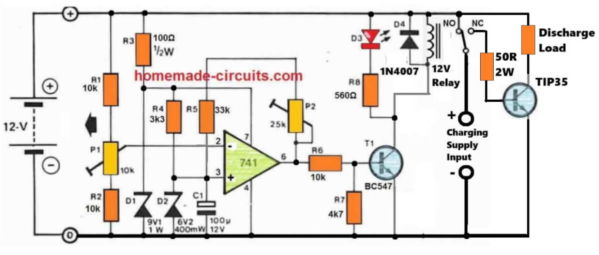
Make sure to use 29V DC “fixed” from the charging side.
To setup the circuit do the following steps:
Initially remove the P2 connection.
Do not connect any supply from the charging input side.
Move P1 wiper fully towards R2 side (ground side).
Apply 29V from the battery side (with no battery connected).
You will see the relay clicking ON.
Now slowly move P1 towards R1 (positive side), until the relay just clicks OFF (N/C). Fix the preset with glue…Your full charge battery cut-off is fixed.
Next adjust P2 to maximum resistance, without any connection to the circuit (P2 connection open with maximum resistance set).
Now without turning off the 29V from the battery side restore the P2 connection.
Now, reduce the battery side supply voltage to 22V.
Start reducing the P2 value until the relay just clicks ON.
Seal P2 with glue….your low battery turn ON adjustment is done!
Now you can remove the DC supply from the battery side and put it normally on the charging input supply side (on the right side) and battery on the left side as shown in the diagram….and start the charging/discharging process…
I have designed th circuit as per your requirements, you can check it in the below given link, it is fully automatic:

Please make sure to make R3 470 ohms and R8 1k if 29V is used, and also replace the opamp with an LM358 opamp…
Hello Sir,
Can we use R feedback lower than 1k? I found the range of lower threshold and auto cut-off is depended on this R.
What is the purpose of 2 diode 1N4007 at the emitter lead of the transistor?
Thank you,
Hello Prapan,
Yes, in the first diagram you can replace the feedback resistor lower than 1k. Those two diodes are added to make sure the transistor does not activate through any false leakage offset voltage from the opamp output.
hi Sir,
It works, it cuts off and switches on at both desired voltages. I apply it for 24 volt charger. Anyway, I found that the relay is flickering on and off at both high/low cut off for a minute before stopping. It happens when the input voltage is closed to the zener diode 4.7 v. Should I increase the R feedback to be higher than 1k to solve this problem?
Thank you,
Prapan
That’s great Prapan,
To stabilize the relay you should actually reduce the feedback resistor value so that the relay kind of latches in that position until the battery voltage reaches the other extreme threshold.
You can also try adding a 220uF capacitor directly across the relay coil to prevent the initial relay chattering.
Hello sir, can I use the lm358 circuit to charge a car battery that is 65 amp hours?
Hello Amir, you can use any standard opamp for these circuit. The opamp does not handle the battery, the relay does.
Ref: LM358 Battery Charger ( Removing the relay and replace with TIP32)
Hi Swagatam, I would like to install a digital Volt/Amp meter (Model No. M3430) into my battery charger, so that I can read the Voltage & AMPS of the battery while it is charging. I don’t know if this is possible? If it is possible can you please assist me as to how to connect it to the battery charger cct.
I don’t know how to send the meter diagram to you. If you can give that info. Then I will send the diagram to you.
Your assistance will be much appreciated.
Regards
Jan
Hi Jan,
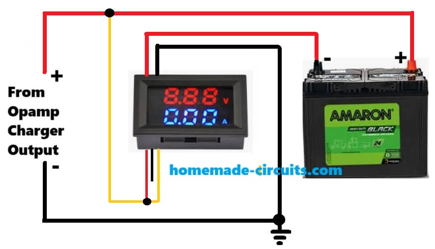
You can connect it in the following manner:
Thank you Swagatam, I really appreciate your help.
You are welcome Jan!
Hi Jan,
Sorry for the trouble, there was a mistake in my previous diagram. The ammeter wires are supposed to be in series with the negative of the load, but I connected the meter in series with the positive of the load, which is a standard practice. But as per the meter specifications it must be connected in series with the load negative.
I have replaced the previous diagram with the new one, please check it….
Hi Swagatam,
Ref. LM358 Battery Charger ( Removing the relay and replace with TIP32)
I have wired up the digital Volt/Amp meter as per your diagram. It works 100%.
I want to thank you for all your assistance with this project.
Just another question: You would not perhaps know of a software package that I can use to make front panel face plates?
Kind Regards
Jan
That’s great Jan, I am glad it worked.
For the front panel designing software, did you try the following ones?
https://www.schaeffer-ag.de/en/front-panel-designer/?lang=en
https://www.emachineshop.com/front-panel-design-software/
You can also try FreeCad, or CorelDraw.
Swagatam, is the diagram currently on your post the correct one. Sorry I just want to confirm this as I am getting a bit confused. So you have a + red wire from the meter going to the – of battery and then a + red wire from the + battery terminal going to the + side of the charger?
Yes, that’s right, that red wire is the thick wire of the meter which measures the current.
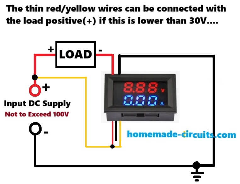
Here’s a schematic representation of the previous diagram:
Hi Swagatam,
Ref. Removing the relay & Presets.
I have completed the battery charger circuit on my breadboard and it seems to be working fine.
However I don’t have a battery available at the moment to test the final step of charging a battery.
Can I replace the battery with a variable power supply? That way I can verify if the charger will switch ON/OFF at the presets settings by observing the red LED.
My concern is the possible damage to the variable power supply.
Your advice will be much appreciated.
Regards
Jan
Hi Jan,
Can you please show me the link to the schematic? I guess you are referring to an opamp based circuit which uses presets.
By the way, you can replace the battery terminals with a variable power supply DC, but then no other power supply should be used from the input side. In this way you can confirm the presets operations. The battery side power supply itself powers the opamp and the relay.
Yes it is the schematic with the TIP32 in place of the relay.
Thank you for your reply.
Regards
Jan
No problem Jan, glad I could help!
Hi Swagatam,
Ref. Removing the relay
In our discussion you refer to ZX which is situated on the 18V solar panel cct.
Then you refer to ZY. Where is this Zener situated?
Regards
Jan
Hi Jan,
I may be referring to the last circuit presented in the following article:
https://www.homemade-circuits.com/battery-deep-discharge-protection-circuit/
Let me know if you have any further doubts in this regard.
Hi Swagatam,
Ref. Removing the relay
I have build this cct on my breadboard tested it with your “How to set the presets procedure” and everything worked 100% using my external power supply.
Problem is the transformer I want to use is 9-0-9 V 50VA of which I will use the 18V tapping’s. I think this is to high? If required how can I lower the voltage to the required value?
Your assistance will be much appreciated.
Regards
Jan
Thank you Jan, for updating the info! Glad it worked for you!
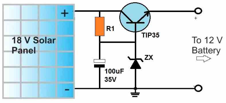
To regulate the power supply to a lower value you can use the following concept:
You can replace the transistor with a 2N3055 or similar. The resistor value will depend on the battery current requirement. Mostly a 100 ohm 1 watt will do the job.
Also, connect a 4.7k dummy load across the emitter and ground of the circuit which will allow you to check and adjust the output voltage with a meter before connecting the battery.
The zener diode value (minus 1) gives the output voltage values.
can this circuit work between 5v to 12.6 Therashold cc/cv for Li-ion battery charging or in Current circuit how many Ampere Limit .
Yes, the cut-off can be adjusted between 5V and 12.6V, but for CC/CV you must include them in your input power supply circuit, let me know if you need any further assistance on this…
sir,i congratulate you for sharing your knowledge for free on internet.but the circuit schematics which u put in this page are tough to understand,they appear like complicated puzzle for soldering.why dont u share schematic created in proteus or multisim.the schematics from proteus are simple to understand and there is very less error while soldering the components.
Thank you Saikrshna, I appreciate your feedback, however, I feel that schematics are the standard way to represent circuit diagrams, and I find them easier to draw. Nevertheless, if you are finding it difficult to understand, please let me know about it, I will try to solve them for you…
Thank you very much for your quick response, but I think I expressed myself wrong. I just need a circuit to put on the multimeter so that the multimeter shows the value by 100…. Example when measuring 300 microvolts on the multimeter it shows 300 millivolts. From already thank you very much.
Thanks Carlos, I think you can connect the multimeter where the 1mV moving coil meter is connected in the diagram, for getting the necessary conversions.
Hello, good afternoon, Mr. Swagatam. You have a circuit available to measure microvolts, starting from 100 microvolts. Since the 3 multimeters I have cannot measure it… Thank you very much Mr. Swagatam.
Hello Carlos,
Unfortunately i do not have any microvolts meter circuit with me at the moment, however I have a microamp meter circuit as giiven below:
https://www.homemade-circuits.com/microamp-meter-circuit/
In the first circuit, I think you can try removing the SW1 switch and all the associated resistors, and apply the microvolt across pin#3 and ground and check if that helps to get any reading on the meter.
Hi
I want to make 6v battery backup with 10 to 18v input, my load is 500ma
My mail id [email protected]
Hi,
You can try one of the concepts explained in this article:
https://www.homemade-circuits.com/simple-dc-ups-circuit-for-modemrouter/
Mr.swagatam,I just want to thank you for this great website. I have learnt a lot from you and still learning more.God bless you.
Thank you so much Julius. I am glad this site is helping you to learn more. Please keep up the good work.
Hi Swagatam,
How to build a low battery indication circuit for my 72v 50Amp LiFePo4 battery pack.Can you please help me on it?
Hi Manjunath,
You can try the following concept:
https://www.homemade-circuits.com/low-battery-indicator-circuit-using-two/
Hlo sir, good evening.. Regarding the second last circuit using Lm358 and TIP 32 transistor, can this circuit be used for charging a 6v,4.5Ah battery? Any changes be applied as regarding the zener or any thing like that? I just need an opamp charger for 6v with auto cut.
Hi Binoj,
Yes you can charge a 6V battery with that circuit. You will have to change the zener diodes to 3 V zener diodes. However you do not need this complicated circuit to charge a 6V battery, you can simply do it with a LM317 or LM338 IC based charger. You just have to set the output voltage to 7 V that’s all, and your 6 V battery will be charged perfectly with a longer life.
Hello @Swagatam,
I am building the second to last circuit that uses the two ics and the TIP32..
I want to know how I can add a function to cut off battery discharging when it reaches 9v (12v battery).. using another TIP32 like we have on the input side
Hello Neddan,
You can apply the following concept to prevent discharging of the battery below a certain specified level:
https://www.homemade-circuits.com/battery-deep-discharge-protection-circuit/
Thank you for the link to that circuit it seems interesting as well. As for this circuit I have some questions as well.
Using the circuit that replaces the relay, I have built the circuit according except for a few differences,
1: I could only find a 1.2K resistor so I used that instead of the 1K.. and
2: I could only find 50k potentiometer instead of the 10k..
so after connecting the desired full charge voltage when setting A1, the LED does not go off or in other words I am not sure of what should be the equivalent of the relay switching in the transistor variant of the circuit. And also, are the changed parts having a detrimental effect in the operation of the circuit?
Thank you for your questions, I will try to solve them.
Yes 1.2K resistor will work instead of 1K.
If you use 50K preset that will be slightly difficult to set the precise cut off levels. But still they should work.
I have updated the information in the above article how to setup the presets of the circuit without the relay.
Please try that setup, I hope it will help you to adjust the cut off levels correctly.
Thank you for your swift reply as always..
The updated steps are very clear and easier to follow..
As for my circuit I found out I made a very silly mistake of connecting the BJTs like MOSFETs effectively reversing their pin connections. I hope I didn’t break any of them as I was testing it on only 12V..
Once I correct that hopefully it should work now
Yes the TIP32 pinouts are different to a mosfet, glad you could find the mistake.
However, please note that while setting up the presets the charging supply needs to be connected from the battery side, not from the TIP32 side.
can this circuit work for 24v battery charging?
Yes, use 24V relay and 9V zener diodes.
ok, thank you
Yes I connected the supply to the battery terminals…
I have a different question concerning A2, which is the lower discharged level preset..
Is the output of pin7 always high as long as the battery is between 10v and 14v ? And then becomes low when battery falls below 10v say 9.9v and stays low unless the charger is present to charge the battery above 10v?.
I don’t know if it makes sense but the idea is that if that’s the case, would it be possible to add an output transistor or mosfet and connect the load via that transistor with the gate signal being the output of A2.
I am trying to learn more about opAmps so pardon the curiosity.
Your understanding is perfectly correct, that is exactly how A2 is supposed to work. The low signal from A2 breaks the latching of A1 and causes A1 output to turn high again so that the transistors are switched ON again and the charging is initiated.
I think that’s a great idea to connect an extra transistor with A2 output and use it to control the load, so that when the battery voltage tends to drop below a certain level, the load is switched OFF
Alright, that is great!. I will try that modification and see if it completes my requirements.
OK, no problem!
And also I would like to know if it is possible to pair one of the op amp battery charger circuits with automatic cut-off with the circuit of the 03 leds which indicate the state of charge of the battery.
You can connect the 3 LED circuit directly across the battery positive/negative line for the required indications.
Good evening please I would like to obtain the electrical circuit of an audio amplifier (100 watt approximately) that can operate through bluetooth or a jack port with all the connections between these elements.
THANKS.
Sure, no problem….You can try the last circuit from this article:
https://www.homemade-circuits.com/how-to-make-simplest-100-watt-mosfet/
if i want to add a blinking led indicator while charging. where can i connect the led. in this circuit?
blinking LED will require another separate circuit which can make the design complex.
Dear Swagatham,
First, I would like to thank you for the superb knowledgeable website. I have learned a lot of technical details about your site and your projects.
And I am planning to build a 5A to 8A Charger for Lithium-ion batteries ( for an Electric scooter) and I wish to build this charger with a good transformer. I hope this circuit is a perfect fit for it.
I want to build a charger for a 72V 20A battery (the 20s. 3.7v 20Ah Lithium-ion 20 batteries in series) this charger has to auto cutoff on 84.0V
another charger I want to build for 60V 20Ah (16s. 3.7V 20Ah lithium-ion batteries 16 in series) this charger has an auto cutoff on 67.2V
I think both chargers can be done in a single circuit.
for this project can you please advise me on what kind of Transformer I have to select? and what modifications I have to do to this circuit.
Regards.
Thank you so much Vishnu,
I am glad this website helped you to learn more
You can use a 0-60V 10 amp transformer ideally and use it to charge the two batteries individually.
Make sure to attach a bridge rectifier at the output of the 0-60 V transformer using 20 amp diodes.
Also, for the filter capacitor you can use a 6800uF/100V capacitor or any other with higher uF value will also do..
By the way which circuit are you referring to for the charging your batteries. Do you have it ready made?
Hi Swagatham, Happy New Year.
Frankly, I never expect this much faster reply!! Thank you So much.
and I am trying to build the PCB design you have provided here.
Thank you Vishnu,

Happy New Year to you too! I am glad to help!
Are you trying to build the following circuit?
Please don’t order the PCB design yet, first build the circuit over a strip-board by soldering the components…if you are able to build the circuit successfully then you can go for the PCB design.
Also this PCB was not designed by me, it was purchased from an external source, so the PCB design is not verified. You may have to verify the tracks physically before ordering it.
I Have another question.
I just try for experiments. Two EV bike chargers (72V 2.5A ) in parallel to charge the battery (to fast charge) and once I connect in two chargers in parallel it shows on the Monitor 72V 5A.
and my Battery was 72V 40Ah. from a 2.5A charger it takes a whole day to charge. and high amp chargers are very expensive. so I try on this way. it is ok to charge the battery like this? I have to connect any diode between both chargers terminals to avoid any short circuits?
if this way is correct can I connect the Parallel 2.5A charger and 5A charger together to get 7.5A?
Since your batteries are Li-ion they can be charged at 1C current rate, meaning your 40 Ah battery can be charged with 40 amp current….so 5 amp is quite less and perfectly safe for your battery.
However, ideally when series cells are used, it needs to be charged through a balance charger.
But in general you can use the present method, with a simple 5 amp charger.
The charger should be having a diode internally, so external diodes may not be required, however for better safety you can connect external diodes also.
You can connect a 10 amp diode at the outputs of the two chargers.
To ensure there’s minimum drop across the diodes you can use schottky diodes instead of rectifier diodes.
Thank you.
Thank you so much for your kind help. and I build my battery pack with a proper BMS. and it has a balancer too.
and I am just following your circuit design. not the PCB. it is possible to build this charger (84V 5A or 10A) with an SMTP transformer instead of a heavy transformer.
Thank you
I think if you have a BMS then the above op amp circuit will not be required at all. You can simply connect the 84V DC from the transformer to the BMS and charge the batteries.
However, if you intend to have an external auto cut off also for the 84V DC then I can suggest you a single op amp easy circuit for your application.
Please let me know if that will work for you.
Any transformer can be used as long as it is a 50 Hz 60 V 10 amp transformer.
Hi Swagatham,
Thank you very much again for your clear reply. and yes I wish to build an external auto cut-off circuit for the power supply with an indicator ( buzzer or any LED after fully charged.
if you have any Circuit for it, kindly share it with me.
Regards.
Thank you Vishnu,
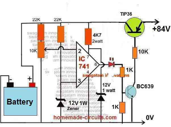
You can try the following op amp circuit with auto cut off. It is a solid state circuit without a relay.
For setting up, feed 84V DC or any full charge battery level DC from the battery side (left side).
Then adjust the 10K preset until the RED LED just shuts off. That’s all.
While actual charging feed the charging voltage from the right side of the circuit.
Good Evening Swagatham,
I already built the circuit and waiting for the transformer. I ask my friend to wind the transformer. I will check it and let you know when it arrives,
And I want to ask one more thing. Is it possible to increase the current value of the original EV bike charger? Like I have a 72V 5A lithium bike charger, is there a way to increase the 5 amps from the circuit to 10?
Regards.
Hi Vishnu,
I hope you are able to make the circuit successfully.
Upgrading the current spec of your charger can be difficult, because you will have to open the charger and do some complex modifications through calculations which may not be possible for you.
Hi Swagatham,
Thanks again I will build this power supply and let you know my result asap.
Regards.
OK, great! let me know how it goes.
I think my previous comment did not post correctly but I’m not sure, so I apologize if this is a duplicate.
The circuits described in this post are precisely what I have been trying to find. I have made some simple circuits with standard automotive relays for my car stereo, and I am mechanically inclined, however I do not know any of the terminology for circuit design.
I have solar panels totalling 45 amps, a 60 amp mppt controller, and (3) 100 Ah deep cycle lead acid batteries that I want to charge sequentially as seperate banks, putting load on a fully charged battery, not recharging it until 45%, and continue to cycle through the 3 batteries this way.
I am also considering possibly adding a different mppt controller that has the feature of linking to the alternator of my van as well.
I would like to know if the circuit shown in the following link is the same as the one discussed in this post:
Are any other pieces needed?
I am hoping to create the circuit using pre manufactured components I can purchase without having to design the circuit and all its tiny elements from scratch.
Thank you for your expertise, and happy holidays!
-Jesse
The unit shown in the link appears to be an opto coupler isolated relay module having 4 relays, it is not a battery charger.
The circuits explained in the above article are precision battery chargers with automatic cut off feature.
So the design shown in the image is not the same as what is explained in the above article.
Thank you!
I guess I was thinking the features of the circuit could be connected to the single charge output from my 60 amp mppt charge controller so that it could charge 3 seperate battery banks one at a time without having to change any connections manually.
The three batteries/banks would be:
1) charging
2) fully charged and ready
3) powering my loads until low threshold reached.
I would like to configure a circuit to make this automatic so the load would not have to wait while I manually switched to the next charged battery available.
It seemed like the circuit discussed in this blog featured a relay and cutoff exactly like I am looking for that could help make charging my multi-bank system fully automatic.
Thank you very much for the response!
Jesse
Yes, that seems possible. I think you can connect separate charger circuits with the individual battery banks to charge them separately through a common source.
You can use the N/C contacts of the relays for powering the load.
All the best to you!
Hi again Swagatham,
Thanks for your prompt reply.
In order to reduce battery consumption during an AC mains power failure I need at that time to isolate the LM358 control circuit incorporating leds too as well as an ampvolt meter I added to monitor the charging process and not only the laptop transformer and the step down module.
I’m thinking of an optocoupler isolation circuit, if you have a page link or a better idea I would be glad.
Hi Sakis,
Without seeing the full schematic of your design it can be difficult for me to understand the situation and propose a solution. Or you can let me know how do you want to connect the opto coupler, I will try to figure it out.
Hi Swagatham,
I want to connect my burglar alarm system with a 12 V 12Ah battery charging by a laptop charger 19V.
I use a step down module at 15V and put on a breadboard the above charger circuit with the tip 32 transistor. It looks working fine after necessary adjustments from 13.4 to 14.2V.
In case of ac power cut i realised that when the battery drops below 13.4V the whole circuit consumes unwanted power even the charger’s led is lit.
Can you please suggest a solution?
Thank you in advance!
Hi Sakis,
you can put a diode in between the charger and the battery which will prevent the battery power from going back to the charger circuit during an AC mains power failure and stop the battery from getting discharged via the charger LED
Hi Swagatham,
I am looking at the circuit under removing the relay, with the LM358, which you posted. Could I use that circuit to charge a 12V 35 Ah lead acid battery from a 80W 17.5 Vmp (VDC) Solar panel. The load would be a 12W wifi router. From what I understand does the circuit exactly what I need like charging a battery and then when full lets the load use the battery voltage. Do I need to change any of the parts you used and to what should I change them? Or could you say how I could find the correct values?
Thank you very much.
Hi Alex,
you assumed it correctly. The load keeps getting the power while the battery is charging and also when it is fully charged. However there’s no facility to cut off the battery from over discharging when the battery goes very low. You don’t need to change anything in the circuit for your 12V battery and the 17.5V solar panel.
But do remember that the setting up procedure of the circuit is not easy, so you must make sure you understand the working of the circuit and setting up procedure perfectly before implementing this concept, so that you don’t run into problems.
Hi Swagatam,
Thank you very much for the quick reply.
How could I implement the cut off for the battery from over discharging when the battery goes very low? And could you explain what the 6A4x2nos is?
Thank you.
Hi Alex,
The 6A4 are 6 amp rectifier diodes. If you are not able to read the diode symbols then I am afraid this circuit may not be easy for you to build.
For preventing over discharge, you can integrate the first circuit from the following article:
https://www.homemade-circuits.com/battery-deep-discharge-protection-circuit/
Hi Swagatam,
I see that it is a diode I was just confused with 2nos as I have not encountered this term yet.
Thank you again for the quick reply.
OK, no problem, then it is fine.
HI Swagatam,
One further question about the circuit under “removing the relay”, with the LM358, which you posted. Does this circuit also work with AGM lead acid batteries? And if not, could you recommend a circuit that works with that kind of battery, preferably with a 12V 35Ah battery, that has the same features, like that it stops charging the battery when the battery is full and starts charging when it reaches a specific point?
And am I assuming correctly that to integrate the first circuit from the following article, to prevent over discharge:
https://www.homemade-circuits.com/battery-deep-discharge-protection-circuit/
I can place this circuit between the battery and load and before the rectifying diode?
Thank you very much.
Hi Alex,
The mentioned circuit can be used for charging all types of batteries since it has an automatic cut-off facility. So AGM batteries can be also used with this circuit. For your 35 Ah battery just make sure that the input current is restricted to around 12% of its Ah value.
That’s right, the deep discharge protection circuit needs to be configured between the battery positive and the load, before the 6A4 diode.
Hi can you send me gerber file please ? my email= [email protected]
Sorry, I do not have the gerber files for these design.
I would recommend you to first build the circuits over a general purpose strip board and confirm the results, before manufacturing the actual PCBs
Hi Swagatham,
i am am looking for a Auto charging cut-off circuit for Electric bike/scooters.
This circuit i have to use for below batteries.
48V 12Ah to 20Ah
60V 20Ah to 50Ah battery
72V 20Ah to 50Ah Lead acid/Nicad/ and Lithium batteries.
Hi M Ali,
you can build the following circuit for all the 3 types of batteries.
Just make sure to limit the current to 10% of the battery Ah for each of the mentioned batteries, accordingly.
Hi Swagatham,
There are some questions I have to ask about this circuit. we are charging all kind of batteries from Normal 2.5A or 5A EV scooter chargers.
we don’t have any charger more than 5A.
1 now in this circuit my main doubt is how this circuit understands what kind of battery (voltage) is attached and when it has to stop charging.
2 10K preset what we will adjust on this circuit
3 TIP36 emitter is for Charge in or Out?
4 12V 1W zener on this circuit it will be same for all 48V,60V,72V, or that zener has to change according to the battery voltage?
Hi M Ali,
With a 5 amp charger power supply you can charge a maximum of 50 Ah lead acid battery. You cannot charge anything beyond this because then the charging process will become extremely slow.
In the above circuit, op amp pin#2 which is connected to preset detects the battery voltage. Because initially when the circuit is connected to the battery the charger voltage will drop to the battery level. This will be detected by the op amp and its output will switch ON the transistors, then as the battery charges and its terminal voltage reaches 56V this will be again detected by the op amp pin#2 and its output will switch off the transistors and cut off charging voltage to the battery.
You can adjust the 10K preset in the following manner:
Do not connect any battery first and keep the preset wiper arm towards the ground line.
Take a variable power supply and adjust its output to 56V or the full charge level of the battery, and connect this supply from the battery side of the circuit. The LED will be seen illuminating. Now, slowly adjust the 10K preset until the LED just shuts off. That’s all, the circuit is all set now to auto cut off at 56 V or at any other selected full charge level.
Now when you connect a real discharged battery, the LED will illuminate initially and as the battery reaches the full charge level, the LED will shut off indicating that the battery is fully charged.
TIP36 emitter connects with the charging supply from the power supply.
12V zener will remain as it is for all batteries higher than 12V. For 12V and smaller batteries, all the 22K resistors, 10K resistor and the 12V zener diode can be removed, and pin#7, preset’s upper terminal can be directly connected with the positive line, and the 4.7V zener resistor can be replaced with a 1K resistor.
Swagatham,
Thank you So much for your fast response and Help.
Best Regards.
Thank you M Ali. I am always glad to help!
Hi Swagatham,
Thank you so much for your fast response and i will study this circuit and let you know my feedback.
Good day Mr Swagatam.
(1a)I would like to know if i can use the op amp transistor solid state auto cut off circuit to charge four times NiMH AA cells connected in series with this circuit. I will use a power supply with an out put voltage set at 5,8 volt 1 amp ( or a bit higher volts). What components and their values do i need to change for this circuit to charge the 4 NiMH 2000 AH AA cells connected in series.
The other circuit for the solar charger that you helped me with, now works beautiful. Thank you so much Mr Swagatam. I am going to save some money now on not buying disposable batteries anymore.
(1b)Can this above circuit also works from a 6 volt 4 what solar panel. I will connect a dc dc boost converter between the solar panel and the circuit to keep solar panel voltage output as stable as possible. This last question marked (1b) is just for curiosity.
Good Day Ian,
Yes you can use the op amp circuit without a relay for automatic charging of your NiMH batteries. You can change the 10K resistors to 4k7, and replace the 4.7V zener diodes with 4nos of 1N4148 inverted diodes in series, meaning their cathodes facing the ground line.
Yes the same circuit can work with a solar panel also provided the solar panel voltage is relatively constant.
I am glad the previously suggested circuit is working for you.
Good day Mr. Swagatam.
I would like to know if the setup of the over charge and over discharge for the charge controller without the relay is the same as for the charger with a relay (the Solidstate charger with transistors). I have built the circuit now and have changed the 10K resistors with 4K7 resistors and I have changed the Zener diodes to as per your instructions and now I just have to set the 2 presets. I am going to charge 4 x NiMH 2000 mAH batteries in series. The fully charge cutoff will be 5,7 V and discharge cut off will be 4 V. Is my fully charged and discharge values, correct?
Good day MR Swagatam.
The Solidstate op amp circuit is working now. Presets are all set with a variable power supply and the red and green Led’s respond to the over charge and over discharge voltages. I just want to find out why my circuit takes so long to charge 4 x 2100 mAh AA cells connected in series. I use a 1 Amp 12 Volt switch mode power supply to bring 220 Volt AC down to 12-volt 1 Amp and then a LM317T variable power supply to bring the 12 Volt down to just over 6 Volt for the op amp circuit. When I put 4 discharged batteries in, the charging from 4 Volt to 4,9 Volt happens fairly quick (about 1Hour 50 minutes.), but then from 4,9 Volt to 5,7 volts ( 5,7 Volt is my overcharge cut out point.) it takes forever. (More than 24 hours.) Do you have any idea why it takes so long?
Good day Mr. Swagatam.
This op amp charger is working VERY NICE now, thank you Mr. Swagatam.
I would just like to know if I can increase the 4K7 resistor value in series with the charging red LED at the base of BC547(As per your instructions i had to change all the 10K resistors to 4K7). The LED glows VERY bright at the slightly higher input charging voltage as per your instructions and I am scared that the LED might fail and causing the circuit to stop working. The very bright LED is also annoying at night. To what value can increase this resistor so that BC547 still switches correctly, but the LED is not so bright. LED VF= 2 – 2.6volt.
Thank you Mr. Swagatam.
That’s great Ian,
Glad to know it is working fine.
Yes definitely you can increase the base resistance of the BC547 to decrease the base current and the LED brightness. The base resistor value of the BBC547 actually depends on its collector current.
The formula is R = (base voltage – 0.6) x hfE / Collector current
However, in your case any resistor value upto 22K should work without any problems.
You can also try the following configuration:
Good Day Ian,
Glad it is working now. NIMh batteries can be charged at 1C rate meaning you can probably supply up to 2 amps to your batteries and check the response. Alternatively you can try using 7V or 7.5V input instead of 6 V and check how it responds. It can be safe to use over 7V since the auto cut off is set at 5.7 V.
If you still have problems you can try the relay version and check whether it charges the batteries at a faster rate or not.
You can try the last circuit from the following article:
https://www.homemade-circuits.com/usb-automatic-li-ion-battery-charger/
Hi Ian,
yes the setting up procedures are the same. I hope you are able to set it up correctly.
I have used the figure 7 voltage regulator with protection diodes circuit found on the data sheets of the LM317T.Datasheet – LM217, LM317 – 1.2 V to 37 V adjustable voltage regulators (mantech.co.za) And the 220-volt AC to 12-volt 1 Amp DC switch mode power supply is a normal wall plug power supply that belonged to keyboard that does not work anymore. (The switch mode power supply still works100%) Is there may be a current limiting on that figure 7 circuit diagram?
Yes the figure 7 and figure 8 have current limiting restrictions.
Hi Sir ,I have made a 4v battery charger with relay cutoff using BC 547 and 10k preset to set the cutoff. But I’m really struggling hard to achieve a well defined cutoff voltage. When i set up the cutoff at roughly 4.6v, and then when i recheck the cut off voltage,it will trip quite early even at 4.2v or 4.3 v. I used the actual battery that is to be charged for setting up the cutoff. I.dont know what actually is happening. I will give the circuit I hv assembled. Your suggestions I’m really looking for.. Thanks srr .
Hi Binoj,
A single transistor cut off circuit will never work accurately, and you will find extremely difficult to set it up.
If you want an accurate cut off you will have to use an op amp circuit.
You can try the following op amp circuit for your application
USB 3.7V Li-Ion Battery Charger Circuit
Hi sir, can I use this suggested circuit for a 4v SLA battery or need any modifications?hv to replace the zener to some other value? And sir pls suggest whether this circuit is good for charging a 6v battery and the modifications needed ..
Hi Binoj,
The above circuits can be used for 6V charging, but might not work properly for a 4V battery. For 6V battery you can also try the following design:
https://www.homemade-circuits.com/make-6v-4ah-automatic-battery-charger/
Mr Swagatam, the first circuit in this post is working as illustrated when I connect the variable supply to the battery point. And whn I connect the battery it can not cut off even whn the battery drains to the low threshold level then the two green and red led lights up. Is it the opam that cannot hold the current and fails or what could be the problem? Is there any other circuit that I can use I a 200ah battery pliz to auto cut in full and low level. Guide pliz
Morris, all the circuit above will auto cut off and auto restore if the presets are setup correctly. It can be actually very difficult for me to tell what may be wrong in your circuit without seeing it practically. You will have to follow the set up procedures exactly as mentioned in the article and also you will have to understand the circuit thoroughly so that you can troubleshoot the circuit yourself. If you are not able to understand any part of the circuit then I can help.
If you want an easier design you can refer to the second diagram from the following article:
https://www.homemade-circuits.com/how-to-make-simple-low-battery-voltage/
Hello sir, I tried to make the first auto cut off in this article. It’s working but sometimes I hear relay triggering trrrrrrrrrr!! Then stops later. How can I prevent it from oscillation?
Hello Morris, you can try adding a 100uF capacitor parallel with the relay coil and see that helps to stop the chattering
Thank you for your kind consideration.
Now I understood A1 and A2 of LM358 is a single unit and I remove one number then connections are changed . Now battery charger function good.
Thank you very much sir.
That’s great, glad you could understand and modify the design as per your own requirement.
Hello Mr. Swagatam, I tried the first circuit here after the failed me and it now works. Thanks a lot sir! Now can u refer me to the best low cut off circuit tha I can use to detect whn the reaches 10.5v to switch off the battery to inverter? Advice sir, the battery is 200ah.
That’s great Morris, Glad it’s working now. The lower op amp A2 works like the low voltage detector. So you can configure a BC557 transistor to pin#7 of A2 via a 10K resistor and connect another relay at the collector of this transistor for enabling the load cut off. Make sure to add a freewheeling diode parallel to the relay coil.
Hello Swagatam, i have configured bc557 with 10k resistorto pin #7 of opam A2. The collector to the relay and emitter to ground but it’s not enabling the relay to activate despite connecting in4007 diode parallel to relay. What could be the problem? Or can u reframe to the other best batty low cut off for inverter pliz
Morris, you must configure the BC557/relay in the following manner:
Sir what’s the rating for this relay? I have configured the bc557 and now am getting 12v and whn I connect the relay it drops to around 1.5v. I have used 12v 30amp relay there. I u have another low cut off for battery to inverter u can as well refer me to the circuit pliz. Thanks
If the voltage is dropping it means your BC557 may be blown, because 30 amp relay cannot be used with a BC557 or BC547. Rating of the relay is 10 amp for contacts and 400 ohms for the coil
For other alternative circuit you can try the following:
https://www.homemade-circuits.com/how-to-make-simple-low-battery-voltage/
Respected sir
I assembled the battery charger using tip32, LM358. But one number IC LM358 gets heated (uper IC-A1). Circuit connection are checked no problem. Please tell what is the reason.
Ramesh, A1 and A2 are from a single IC LM358, they are not separate ICs. This IC can become hot either if its output pin is shorted or if the IC itself is faulty, or if the supply voltage exceeds 32V….otherwise this can never heat up.
Hello my Swagatam, hope you are fine. In this article I see automatic cut off circuit diagrams for battery charger. I want use the one with dual opam(Lm358) and the last circuit with single opam(Lm471). Do they work properly sir? Advise….and do I use a 12v 30amp to carry the charging? Thanks.
Hello Morris, all the circuits will work properly if you build and test them properly. So it is very important that you first understand the working perfectly and only then build it, this will help you troubleshoot the circuit if there are any issues with the connections.
The transformer current will depend on the battery Ah rating. Use a transformer having a current rating that’s 1/10th of the battery’s Ah rating. I am referring to a lead acid battery
Hello sir, how can I set the two presets in the second cut off circuit with rectifier? I have tried the procedure for the first circuit but it’s not cutting off when the battery reaches the maximum voltage 14.2v. Which one of the four circuit can I build?
Hello Morris, all the circuit will cut off correctly if the presets are set correctly as per the instructions. I have tested the circuits, they all worked for me.
Hello Swagatam, lead acid battery is the one being topped up with acid or distilled water or it’s is dry sealed battery? Can the circuit work with dry sealed batteries (free maintenance battery) then. Advise and help me differentiate, I beg. Thanks.
Hello Morris, the circuit can work with all types of batteries, just make sure the input current is controlled and limited as per the battery specs. All lead batteries whether sealed or unsealed must be charged at 1/10th of their Ah value.
Hi Swagatam
Thank you for sharing your knowledge with so many of us who are not always privileged to go to university, but still have the desire and passion to learn and play with electronics – thank you ever so much.
I want to confirm with you if my thinking is correct – I have a 36V Li-ion battery charger, I want to add overcharge protection to the unit using your dual op-amp circuit. The problem I am having is that the LM358 can only operate to a maximum supply voltage of 32V. How will I bootstrap the opamps to tolerate the high charger voltage? I do not have immediate access to the high voltage opamps such as the LT6090 or LT6091. your kind response will be appreciated.
Thank you Hennie, the pleasure is all mine!
For 36V li-ion charger you can try applying the simple concept which is explained in the following article: For the input supply I guess you will have to use 37.8 V
https://www.homemade-circuits.com/make-this-48v-automatic-battery-charger/
Swagatam, thank you for the prompt response. I will build the simplified automatic circuit and let you know if I experience any issues. Thank you for your kind support.
No problem Hennie, I am always glad to help!
Plz sir u modified the 2nd design by reconnecting the output pin of IC2 to the base of the bc547 via a 1n4148 zener, Plz sir what could be the reason
Nimel, I don’t remember the previous diagram so can’t clarify the reason…
I mean the design that has a transformer
I cannot see any diagram that has 1N4148 at the base of BC547
Plz sir in the second design i think the upper LED should be reconnected as:cathode to pin8 and anode to pin1 to indicate the batt full condition since at the high threshold level the upper IC’s pin1 goes low and no LED will be illuminated at batt full instead they illuminate during charging process
Nimel, you can do that by connecting a 3rd LED. However, for this LED the cathode will go to the op amp output and the anode to pin#8 or the + supply line. Make sure to add a 1K or 2k2 resistor in series with the LED.
Hello Swagatam,
Just wanted to convey my Thanks for this charger circuit (solid state transistors model). I could successfully built it and put it into use for my router at home as a mini UPS.
Glad, I found your website last year; since then, I go through several UPS related circuits and comments. Admire your dedication towards electronics; Amazing patience to answer almost all questions; You are a Great Soul.
Note: I was an electronics hobbyist during my 10th standard. Revisiting now, at the age of 53.
Thanks
Mohan
Thank you so much Mohan, I am glad you found the concept useful, and I truly appreciate your kind feedback! Please keep up the good work!
Hello Swagatm,
Seeking your help on the above transistor based op amp charger circuit that I have built recently. It works fine with 12v 0.5A router (Mi Router 4c). But it does not work with 12 1A router (Linksys E5600).
My setup has: charger circuit + two li-ion cells (18650 2c) + XL6009 step-up booster module. If I try with mere li-ion cells + XL6009 step-up converter module, it works.
I am unable to identify root cause and believe it should be handling 1A current rating too, but it is not.
Appreciate your guidance. Thanks for sparing your time.
Thanks
Mohan
Hello Mohan, can you please explain how all those units are connected with the circuit. And also please specify what is exactly not working?
Hello Swagatam,
For flexibility, units are connected using DC Jacks, pin headers, female-to-female dupont cables.
Working of this circuit seems unpredictable. Before writing this message, I tried to test it several times and write a problem-description. It worked well as expected except one time (occurring similar scenarios frequently).
Here is my observation of the problem:
On mains supply, the router works fine. On power failures (actual power failure and mimicking), both Charging LED and Battery Low LED are ON for a short time, say 2 or 3 minutes, then Charging LED goes OFF or DIMMED. Now, Router’s power goes off, internet connectivity is lost. In such scenario, it seems router is getting only 4 volts and hence causing router to power off. Waited for few more minutes, circuit’s both LEDs are getting ON, router gets 12v and powered on.
Hope this description helps.
Thanks
Hello Mohan, I meant to say where is the boost converter connected and why it is being used? As you can see in the diagram, the charging supply and the battery both are directly connected to the load, the op amp circuit has nothing to do with the router, so it cannot affect or get affected by the router, it is only responsible for charging the battery, and indicating the charging ON/OFF conditions.
Do you mean to say the battery is not getting charged when a 1 amp router is connected?
Pls is they video for this circuit ? .
Pls can I substitute the preset resistor for a variable resistor?.
Can it charge car battery 12V?
Sorry I do not have a video for this, but I can assure that the circuits will work. You can replace the presets with fixed resistors after confirming the values
What is the block diagram of automatic battery charger
Sir can we do physically is it works
I have tried the above “alternative design” both on TINA-TI simulator and on PCB, both works like a charm. If one seeks greater precision over different external conditions, guess the Zenners could be replaced by TL431 and the potentiometers with DigiPOTs, with other appropriate discrete components.
Many thanks for the great article.
Thank you so much for verifying the design in your simulator tools…
yes definitely, all those mentioned parts can be upgraded appropriately for getting enhanced precision.
on this battery charger circuit with auto cut off wheres the 1n4007 in series with the relay on the PCB layout,and on D1,D2 witch one is red and green.Im going to use a LM324 do you have a PCB layout for that? thanks your admierer, JOHN
I think the PCB design may have some flaws as it was designed by a nonprofessional designer, please check it and correct the faults accordingly.
Yes LM324 can be used by replacing the pinouts appropriately.
dear sir! i also made a circuit someone like this, but i’m facing a problem continuously
when i connect the charging circuit output terminal (O/P = 13.8vdc) to 12v/65AH battery. the battery goes instantly to 13.8vdc and relay cutout. actually the battery is not charged to 13.8vdc but when charger
goes to connect it cutout instantly not really charging the battery but instantly cutting out relay what’s the possible solution to this problem?
Dear Sheraz, what is the current rating of the charger output? I hope it is below 15 amps. In that case your battery is defective, it is not accepting the current from the charger and the voltage across its terminal is rising quickly due to lack of current absorption.
it’s an smps battery charger, the charger output rating is above 15 Ampere by putting heavy load, also the battery is new 12vdc/65Ah battery. but the circuit is showing the problem with every 12vdc/35ah, 65Ah, 80Ah etc. not the problem that the battery is defective.
Then it means your battery is already fully charged. A fully charged 12V battery will stabilize to 12.5 V (SoS) in idle conditions.
Make sure your SMPS current is not more than 15 amp at any cost for 65 Ah battery, ideally it should be 7 amps, or 10% of the Ah value
Hi sir, nice explanation about the circuit.
I need 48v 6amp lead acid battery charger circuit. Can you please explain..
Hi Nandhakumar, you can try the following circuit:
hi Sir,
what changes to made on the above circuit to charge 24 v 150AH battery.
Thanks,
Hi BG, no major changes will be required, just replace the relay with a 24 V relay, and the charging supply with a 29V DC supply
Here’s what you exactly need to do, the LED status will clarify the positions of the various stages
And please do not assemble it over a breadboard, that would be like inviting mistakes. Assemble the circuit over a veroboard or strip board by properly soldering the parts.
Also please replace the BC547 with 2N2222
Thank you for taking the time and effort to explain the why’s and whatnot’s. I built the last circuit with the TIP127 and it works the way it is supposed to with the triggers when testing with bench power supply to but there is a major heat issue on the 100 Ohms 2 watts so I could not finish charging a battery in full when testing in real life. I have measured the temperature of the resistor to be 105.8°C and it was already cooling down so I stopped everything and I am wondering if putting resistors in parallel at the base of TIP32 would help in taking the heat or if there is another solution to keep charging at 1 A at least without risking a fire? If using MOSFETs, what would be your solution? I am more used to building small circuits where power sources are not much of an issue but my current project is tougher than I thought it would be.
The second BC547 driving the output MOSFET was fried actually, I replaced it with a new one and to be sure we are on the same page, I went back to the zener and 10K at PIN8. The locks are working now and I get full voltage at the output. Now, you told me earlier how to connect the output MOSFET but without the feedback with the 1K between gate and PIN1, I cannot get any output. Just for test, I temporarily have connected an LED with a resistor in series on the output MOSFET drain with the output to check if it was disconnecting when charging at the input and it does, I removed it as it was dropping too much voltage at the output. A last thing, I need to use a switch to save the battery when not in use but when the battery comes back online with a lower voltage than the higher threshold or if the battery is full and a load kicks on, the charging LED lights up, is there any trick to avoid this? Do we need another Opamp as a comparator?
The second BC547 shouldn’t have burned because its base is protected by the 4k7 resistor and the collector by the 1k across gate/source of the MOSFET
…Are you referring to the battery self discharging through the 10k preset while it is not being used? This can be probably prevented by shifting the 6A4 diode from the indicated position to the point exactly between extreme left 10k preset positive connection and the battery positive.
Glad it is working now!
There are a few things that must be correctly calculated to ensure proper working of the circuit.
The input current must be preferably no more than 50% of the mAh rating of the Li-Ion cell. For example if the the cell is rated at 2600 mAh, then the charging current should be kept below 1.5 amps.
The base resistor of TIP32 must be calculated using the formula R = Input V – Battery V / Charging Current
R wattage should be = (Input V – Battery V) x Charging Current.
If a MOSFET is used in place of the TIP32, then the gate resistor becomes immaterial, and this could be an ordinary 1k 1/4 watt. However, the battery charging voltages should be in the range of 10 V to 15 V
I found the reason why the input kept charging despite the battery being full with no LED ON: the P-MOSFET on the load side leaks through the drain toward the source when power applied at the input. So I changed this MOSFET for a N-MOSFET IRLZ44N and a 1K between gate and source, that stopped the bleeding but there is still a tiny leak I cannot figure. If the battery is charging with “charging” LED ON then the battery is disconnect from the load and zero Amp is consumed as long as it charges but when the charge stops with the charger still powering the load, the battery reconnects to the load or something else and it draws 0.0048 A for a 12V battery. I tried with a TIP127 and it draws 0.0037 A in the very same condition.
But the battery is connected at the source side of the MOSFET, then how can the leakage be from drain towards source? Is it the load side MOSFET or the charger side MOSFET that you are referring to? Also remember there’s an internal diode with every MOSFET, so check if that is affecting the situation?
And if you change the load side mosfet with a n channel, then you will have to eliminate the new BC547, and connect the gate directly with the old existing BC547, and also remove any resistor previously suggested across gate/source of the n-channel mosfet.
I do have an issue I cannot understand now that I am testing the system completely. I removed the “Full” LED as it was more of a distraction. The system is complete with a load running on a fully charged battery, no LED “ON” which is normal but if I connect the power at the input, the battery disconnects from the load and start charging while the load is powered by the charger. Isn’t the charging supposed to start only if the “Low” LED triggers the “Charge” LED? I have checked multiple times the circuit against the schema and I don’t see an error.
That is normal, because when the charging input is switched OFF, the latch breaks, and when the charging supply is switched ON back the A1 restores the battery charging by switching ON the transistors.
This can be perhaps corrected by adding the following circuit in the existing design:

….You can change the 1k to 10k for reducing unnecessary current dissipation
Moving the diode did not change much. Self discharging will always occur anyway due to the BMS but it is more about laboratory safety that I need to have a switch to disable the device when not in use. This circuit is the closest, to date, I could find on the web for the very specific usage I need. It is going to be used in a laboratory setting to power a liquid flow meter where ambiant air may be filled with ethanol and a power socket might no be available. I will implement a battery meter with a push button for quick readings and a low battery alarm with a buzzer to make sure people will react when battery is going to die to plug the power in time. Due to the specific requirements of the device, I had to add an adjustable voltage step up at the output and this makes all the voltage monitoring a bit difficult. I also needed an adjustable power boost to charge the battery when empty which would not trigger the high threshold too easily. At 25V, it is way more difficult than at 12V!! But it works, thanks to you and I really appreciate your help!!
The diode will protect self discharging only from the 10k presets and the associated opamp circuitry. Anyway, glad the circuit helped you to achieve your objective, now it needs to be confirmed over a well deigned PCB before the final implementation.
Well, I discovered the source of the issue with the high threshold which didn’t want to latch, it was a poor contact on the A2 trimpot towards ground, that was all my fault, so I fixed it and I got back to original 10K at the “full” LED and it worked. I also removed the 15V zener and the 10K which were connected to pin 8 of the LM358 and that reduced the voltage drop down to 0,35V which is way better. The voltage drop actually occurs as soon and as long as the “full” LED switches ON with or without a load. I kept the output MOSFET though.
No problem, actually a hardware fault is a common thing that we all come across with electronic circuits, and this inevitably happens with all hobbyists and engineers. However, if the circuit is thoroughly understood then troubleshooting becomes easy and quick.
Coming back to the circuit, if you remove the 15V zener from pin8 of the IC, then the low battery indicator (green LED) might not work correctly.
And, as long as the red LED is ON (battery charging), the left side MOSFET is supposed to be fully cut off, therefore getting any voltage at the drain of the left side MOSFET should not be possible?
Yes, all measures were done with respect to battery ground with or without a load. The only moment I could get full voltage at the output was when I tried to short the gate of the MOSFET to ground but then, the battery would be charging when the charger is connected even if the « charging » LED was OFF. I think, I will try to go back to the TIP127 for the output.
But that again sounds against the standard laws of electronics. If you short circuit the collector/emitter of the BC547 associated with the charging MOSFET (right side MOSFET), would mean shorting the base of the other BC547 associated with the battery side MOSFET (left side MOSFET). In this situation, the other BC547 will stop conducting, cutting-off ground bias for the left side MOSFET, and this should shut down the left side MOSFET, so how is it possible that you are getting full voltage in this situation, ……which will also mean that the battery will be depleting while charging.
I have changed the 1N5408 for a 6A4, it should be OK (the battery must drain before next test). Up to now, I was focused on the charging side but now there is a new issue: there is a 4.5 to 4.8V drop between the battery terminals and the output and I measured the drop to happen right at the MOSFET drain on the output side. This is so weird! Even stranger: if I plug an unpowered a charger, I get the full voltage of the battery at the output! When powering the charger, it works as expected, but I am puzzled by the 4.8V drop on battery only.
Did you measure it with respect to the ground line? Meaning, the meter probes connected across drain and the battery negative? You can also try shorting Gate terminal directly with the battery negative and check the response.
And did this happen with an appropriate load connected at the output side or without a load? Please confirm the same with a load connected.
Thank you so much, it works great! Now, do you have any suggestion for the 1N5408 which is burning hot when charging the battery @ over 2A? A 7000mAh Li-ion battery takes too long to charge if we reduce the amperage too much but I don’t want to burn a lab either. I also noticed a current surge on the load output when connecting the charger: the high amperage required to charge the empty battery seems to leak a bit too much to the load but this, I think, I can find a fix.
Glad it’s finally working as required! 1N5408 is rated to handle 3 amps max, so 2 amps can make it red hot indeed. You can replace it with a 6A4 diode, but even this diode might get significantly hot and will require a good heatsinking.
Alternatively you can also check the response without including this diode at all.
Thanks a lot for your time! The main issue was more on keeping the latch than breaking it actually. I could verify all the latch breaking, thanks to your explanation. I managed to keep the latch @ 25.2V by just changing the 10K in series with the “Full” LED by a 15K. Now PIN 8 has a 12V Zener instead of 15V since the battery itself will drain down to 15V. The second “Charging” LED in series has been removed as it was rendered unnecessary. Now I need to find a way to drive properly the left N-Channel MOSFET IRLZ44N. Should I use a P-Channel MOSFET on the left too?
Glad you could solve it so quickly!
For the load side MOSFET a P-channel will be required and will be more suitable than a N-channel….you can do the following modifications:
1) Add another BC547, by connecting its base with the collector of the existing BC547, emitter to ground line, and collector directly with the gate of the load side p channel MOSFET.
2) For the MOSFET, just connect a 10K across its gate/source, and nothing else. The source pin will connect with the battery positive as done earlier, and the drain will connect with the load side output, as per earlier configuration.
We are making some progress!! Now with the “Low” LED on 8 and 1K with the 15V Zener in addition to a second LED in series with the charging and the left side MOSFET detached, the latches work even though the “full” LED starts to dim ON at 17V all the way up to 25.2V but this time, the charging LEDs switch OFF. Once the charging LEDs are OFF, output 1 measures 1.12V @ 25.2V. Output 1 reaches 0.9V only @ 18V. Output 7 works perfectly but is never @ 0V, it reads 1.02V when set @ 15V. However, when I reattach the left MOSFET side, the high latch does not work anymore.
The latch will break and the charging process will be restored only when the “low” at pin7 pulls the pin2 level of A1 below its pin3 level. Since A1 output is 0.9V this means the pin3 will be dragged approximately at this 0.9V level by the 1N4148/1k feedback. When the A2 output turns low at 15V, it’s output turns 1.2 V, which looks a bit higher than the 0.9V, which implies the latch cannot break. For the latch to break the A2 output must drag the pin2 of A1 below the pin3 level.
This could be probably adjusted by increasing the 1K in series with the 1N4148 to may be around 4k7 or 10k etc
The left side MOSFET will not work correctly in this modified version unless a separate BC547 driver is also added with this MOSFET
Unfortunately, nothing seems to be workingwomen it comes to use any voltage above 20.8V for some reason. I have tried the 10k resistor in series with the pin8 of the op amp and both the “charging” and “full” LED were glowing dimmed but could only latch at 20.8V, it did not work above this voltage. I tried with the 15V zener across pin8 and the ground in addition to the 10K resistor in series and this time, the “low battery” LED was switching ON as soon as the voltage reached 15.5V and stayed ON all the way up. It only dimmed OFF only around the 15.2V and switched back ON on preset 15V. I could not go higher than 20.8V either to latch the settings. I even tried to power the LM358 with 12V and then 5V using 7812 and 7805 ICs with no more luck. It is way above my current skills.
Yes the low battery will now stay ON, because pin7 is turning high with 15V, while the green LED anode is at 24V.To correct this please connect the green LED anode side with pin8 of the IC, and replace the a 10K at pin8 with a 1k so that the LED can get proper current.
Now, to check whether your op amp is working correctly or not, you can remove the left side MOSFET stage entirely, then remove the latching feedback also across the A1 op amp.
After this supply the upper and lower thresholds from the battery side using a variable power supply, and then rotate presets to make sure the LEDs switch ON and switch OFF according to the general rules or a comparator.
The basic rule is that when the voltage at the (+) input pin of the op amp is higher than its (-) input pin, its output will turn high (or equal to its pin8), when the (+) is lower than (-) then the output will turn 0V.
Please conform the above using a multimeter, if you find the op amp output not turning 0V fully, which may keep the transistor switched ON permanently, you can correct this by adding another red LED in series with the BC547 base which should cut off the excess leakage voltage and allow a total switch OFF for the BC547.
Unfortunately, the circuit does not accept a high threshold over 21.8V. The charging LED never switches OFF but rather dims a lot and the “full” LED switches ON quite dim as well and the locks only work at = or < 21.8V, over this voltage, the locks do not work at all. I am wondering if we should not change the potentiometer at A1 for a higher value. What do you think?
The input pins of all op amps have very high resistance, so the value of the preset shouldn’t be relevant. Any preset between 1k and 100k can be tried, all should work equally well.
The problem could be due to high current/voltage at pin8 of the op amp which might be causing high offset or leakage voltage at the output of the op amp and is not allowing a full 0V at the output.
You can try a 10k resistor in series with the pin8 of the op amp, and then put a 12V or 15V zener across pin8 and the ground.
This should solve the issue, but now this will not all the battery side MOSFET to switch OFF, since a 12V or 15 V output from the op amp will be lower than the 25V at the source of the MOSFET which will never allow it to shut off.
This can be remedied by adding another BC547 stage for the gate drive of this MOSFET.
You can try this later on once the op amp switching problem is solved using the above explained procedures.
Thank you for your super quick new design, I was not expecting so many changes. May I kindly ask you which value should be used for the Zener diode at the charging point in this new design?
You are welcome! The zener diode can be a 15 V 1/4 watt diode.
I replaced the TIP32C with a MOSFET IRF4905 and now, I can charge my 12V 7000 mAh in about 8h with no alarming heat which is great. However, that was the proof of concept phase with low voltages. I would need to use this circuit with a 25.2V Li-ion battery and when I try to set the high threshold, the charging LED dims a little bit but never switches off when the LED on the TIP127 lights up thus, the other triggers do not work. It seems that the highest voltage accepted for the battery around 15V and above 15.5V, the locks do not work anymore. Which resistor should I change to make it working with voltages above 24V?
Please try the following modified configuration, and check the results:
Make sure the charging input supply is 1 V higher than the battery full charge spec.
Hi Swagtam, can u make a circuit practically amd make a video on it.. coz, alot of ppl around here are facing some sort of problems. Pls i also gave up making a 3.7volt lion battery charger. My idea was not fulfilled.
Hi Chandrashekhar, Can you please explain the testing procedures you have used to confirm the various stages of your circuit? if you try it randomly without understanding the steps then you are bound to have problems. I have already tested and applied similar designs many many times for battery charger applications successfully. These are very basic concepts using op amp compartor.
If you can specify a mistake in my design then definitely I’ll look into it. But for that you must be first able to check it yourself, right?
You can see one such working example here using a single op amp:
USB 3.7V Li-Ion Battery Charger Circuit
You can apply the following modifications around the TIP32:
Good day sir,
please if i use a 12volts,400ohm relay for the above charger,will it be okey for 10Amp requirement bearing in mind that v/r = i > 12/400 =0.03amps.Will the relay and the transistor handle this current level ?.What do you suggest sir?.Another thing the resistor needed for the constant current will be too small to find in the market.
Patrik, the 400 ohm is the resistance of the relay coil, and cannot be used for the calculations. The best way is to check the printed rating on the relay itself. It should be rated at 30 amps/220 V to handle 10 amps comfortably.
Hi Swagtam, i have tried every possibility but the lm358 never gives the exact output as the vcc voltage.. always there is a drop of 1.3 volts… Pls make a video on the output volt..
Hi Chandrashekhar, there may be some offset voltage difference at the output of an op amp, but still that is enough to switch ON the transistor. In your case it is 3.7 – 1.3 = 2.4 V which is more than enough to turn on the BJT.
Hello sir,
Can i use this circuit to charge a 12 volt battery while providing output to a 12 volt 2 ampere load with an adapter of 12 volts?
If yes then please guide
Many thanks in advance
Hello Eshu, yes that’s possible using the first circuit but the input supply current must be sufficiently rated to charge the battery and also handle the output load.
Thanks for your response and help
Actually i don’t want to use a relay for switch over. Can i use the last circuit for my requirement as i want fast switching from mains to battery to supply the load
yes surely, you can try it.
i yam using a variac tranformer for a variable supply with a bridge rectifier this works well i can charge anything to any set volts and amps all your work of great interest
Hi swagtam , i want to use the 1st circuit without using a relay. can it be possible to use transistor based circuit beside relay?
Hi Chandrashekhar, I have updated the required design at the end of the post, you can check it out. Remember to disconnect the feedback 1k/1N4148 while adjusting the presets. Connect it back once the adjustments are done.
hello sir swagatam,please let me know the changes i should make to the circuit incase am monitoring a 24v battery?
Evans, Use a 24 V relay, and a 24 V battery, rest everything can be as it is.
Hi swagtam, in the last circuit where u put TIP transistor, i saw the unusual behavour in the spice simulation. Is is works in real circuit. pls confirm. coz i will make an good quality pcb for the circuit.
Also i want to charge 3.7v 6600mAh LI-ION battery. Is TIP transistor ok for that . Please confirm early. ALso tell the zener value for 3.7v charger circuit. Is it 3volt zener.??
Hi Chandrashekhar I cannot comment on simulator behavior, but according my own brain simulation the circuit is perfect and will work. However, the person who is building the circuit must first understand the working of each and every component, otherwise troubleshooting may become impossible in case an issue arises. So I would recommend you to spare some time to understand the opamp comparator working, and only then proceed. Also, a PCB must be designed only when the prototype is tested and confirmed on a veroboard…these are the some basic electronic rules that all must follow. TIP will support 3 amp current (on heatsink) so it looks ok to me. You can replace the zeners with two series 1N4148 diodes, with cathode towards the ground line.
ok. thanks for early reply. i definitely trust on ur Brain Simulation. I will first try on blank pcb coz i have no veroboard then i will make an pcb..
Thanks for giving such wonderful Website.
Qsn no-1: Sir, how to over discharge feature will add to your last circuit.? Pls expain.
Qsn no-2: Again for a comparator, when inverting input get low than non inverting then we can get full input voltage. But in my case the voltage drop by 1.3volt why. Pls..
Chandrasekhar, I have updated the explanation at the bottom of the article. When the (+) input of the comparator goes higher than the (-) input, its output will become equal to the ICs Vcc voltage or the full supply voltage. Check your comparator with 6 V or 12 V, may it is malfunctioning.
How to Use an Op amp as a Comparator Circuit
Ok, Sir pls let me confirm that on your last circuit which u have designed, i want to charge 3P Li-Ion battery (i.e 3600Mah 4.2v) with it and load LED will be 250MA total. Hence pls tell me the resistors, zener and transistor for the circuit for modification. Awaiting for early reply
Chandrashekhar, for the mentioned application you can change the zener diodes with two series 1N4148 diodes with cathodes towards ground side, and replace the red LED with a short.
Ok Sir, I have given a circuit diagram link with necessary modification for automatic LED on-off feature. Pls have a look and suggest if is there any correction in it.
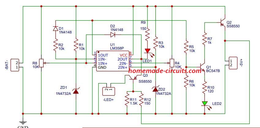
Thanking you for your kind co-op.
Thank you Chandrashekhar, that looks great…however due to lack of time I won’t be able to confirm your version of the schematic. If you have any questions regarding the schematic which I have updated in the above article, please let me know I’ll solve it for you.
Thank you for trusting me Chandrashekhar, I wish you all the best. I have made a couple of changes around the upper op amp pin2/3 connections, please make sure to do it accordingly.
hi, this is REvocatus from Tanzania I want to know how can use a transformer from UPS lated at 850VA as a battery charger for 100AH or 50AH battery with auto cut off. If you have a diagram or any advise please provide it, I hope you will help me. Thanks
Hi, you can refer to the following two articles for more info:
Designing a Customized Battery Charger Circuit
Lead Acid Battery Charger Circuits
Hello sir,I like the idea,so how can I connect this to an existing inverter to make it a ups? With an aid of a diagram,I’ll appreciate.
For a UPS design you can read the following article:
https://www.homemade-circuits.com/making-ups-tutorial/
Hi Mr Swagatam, thank you for fast reply so now I want to know which type and size of the rectifier diode I should use to match with this transformer? also should I add a capacitor on that rectifier diode or not, if yes which volue of the capacitor I should use?.
Thanks.
Hi Revocatus, for charging lead acid battery, the diodes must be rated with current that’s 20% of the battery Ah. Transformer current rating must be 10% of the battery Ah. Filter capacitor is not required for charging a battery
Hi thank you for nice explanation, so can I use this transformer from UPS to charge battery, the UPS is rated at 800VA and the transformer input is 230V output 7.5v-0-7.5v?
800 / 15 = 53 amps that’s a lot of current. Unless your battery is a 500 Ah battery you will need a current controller stage to limit the current to 10% of the led acid battery Ah.
Pls,is the component value at (R2 = 0.6 / charging current) a resistor or what?
It is a resistor.
How can I configuration this circuit for 24v battery?
replace the relay with 24v relay and set the circuit for cutting off at 28V high and 22V low
Can i use potentionmeter instead of R2 resistor R2 = (0.6/ Chrg Current) for control current in above circuit.
Second how much current can handle above circuit.
I have 15v transformer but i dont know current rating when i install 35amp bridge rectifier it have burnt instantly. Can i use 2 50amp diode for rectification?
Sorry for lenghty question but ur ans will be very helpful for me.
If you can arrange a 1 ohm pot then you can use it. Diode will burn if the load current is high, not because of the transformer current rating, so make sure the load is not an overload. The diode current should be 2 times the charging current of the battery.
Please sir, what can I do, when I use 10amp 12v relay, the response is faster than 30amp 12v relay
different relays will have different response times…so we can’t do much about it.
Sir, I am proud of you. I have build your modified sine wave inverter circuit successfully. I have added one of your charger circuit,using lm358. I used 20amp battery for the inverter. Sir pl. Clarify the following :
1.In charger circuit around Lm358 how can I identify upper threshold
pot,and lower threshold pot.
2. Which diode can be used for reverse polarity protection. Can it
be 6A Diode
3. The charging transformer is 18volt 2amp. Can I charge 30 amp
battery with this transformer.
4. I am having a UPS transformer with 3 wires in secondary side is to
be connected to the inverter circuit. And the other side it has 7 wires
out of which 2waires( paire) , when connected to rectifier
gives 12volt 7amps. Can I use this tapping for charging 20amps
battry. If so how can I reduce the current to 2amp. Can it be possible
using Lm 338 circuit.
Sorry sir, for the long questions.
Thanking you sir,
Leelesh.
Hello Leelesh, here are the answers.
1) Keep the upper preset to ground level, and the lower preset to positive level. From an external variable power supply, apply 14.2V across C1, you will find the relay clicking ON. Now slowly adjust the upper preset so that the relay just switches OFF. Next, reduce the input voltage to 11V, and slowly adjust the lower preset so that the relay click ON again.
2) Yes you can use 6A4 diode
3) Normally 3 amp is advisable for 30 Ah battery, 2 amp will make the process slow and may take 20 hours for optimal charging
4) you will need 14.2V for charging a 12V battery, 12V will not work
I am Bernard Tendengu.
On the operational amplifier comparators the 741 and the LM 358 both presets are 10k ok I am getting lost
on how you got the values of the other 10 k resistors which are connected to the 6v zener diodes. Did you use the voltage as 12 volts from the relay to calculate the resistors as well as the current passing through the relay as 40 amp.
Accurate values are never required for these kind of semiconductor application. The zener provides us with a wide range of current through which it can operate optimally. You can use any value between 1K and 10K. I did not mention 40 amp anywhere in the article, and it is not relevant, as long as the voltage is 12V. If the voltage is significantly higher then the current will matter.
dear mr….
i wish to change my motorcycle’s sla battery with li ion18650.. and could to drive high power led 200w power output.. is this circuit safe?
should me to add bms 3s board?
answer me please to [email protected]
This is not for motorcycle application. I would recommend a LM338 based constant voltage constant current module set at slightly lower than the full charge level of the battery…this will be safest way to charge it.
Hello sir. Actually i wanted to refer the first circuit (load is connected to the supply) other than the modified one. The things i wanted to know is:-
1. What must be the range of input voltage and current for the safe working of the circuit.
2. What are the specifications of the relay to be used. Is it dependent on the type of battery to be charged. If yes, then what are it’s specifications.
Please do help sir.
Is it a must to put 12v zener across the emitter and collector of T2 if my transformer is 12v, can I use BC 548 as T2?
zener won’t be required if the supply is 12V. BC548 will do for T2!
Hello Ashish,
The IC can tolerate a maximum of 30V, so the input supply should not be increased above this value.
The relay coil voltage can be as per the battery voltage, if it’s 12V then the relay should be also 12V. The relay contact current rating should 2 times more than the charging current rate of the battery. Charging current should be ideally 10 times lower than the Ah value of the battery for a lead acid battery
1.If am going to charge 12v 100ah battery, will I use the charging current of battery as LOAD to calculate the value of R2?, let’s say if is a lead acid; 1/10 that is 0.7/10A or what?.
2. In your earlier post you said for charging lipo or polymer batteries it is recommendable to charge 5% for their efficiency and current control charger, can i use this last circuit with 1/10 , that is; 12v 10A rectifier to charge my polymer 12v 100ah battery?
Hi, I have issue concerning power supply and I ask for your help/ guidance. I have a power amplifier which needs 24v 7amp and the transformer available in market is 24v 5amp and when I connect it with 24v 5amp the amplifier output is not sufficient and transformer becomes so hot when I vary volume to max, my question is, can I use two 2 transformer in parallel to amplify current to 10 amp and how to connect them
Yes that’s possible but you will have to do this by adding separate bridge rectifiers at the two transformer outputs, and also separate filter capacitors for the respective bridge rectifiers.
yes you must use the charging current as the load to calculate R2, I have updated the formula under the second last diagram.
sorry i did not get your second point, what is “5% for their efficiency?”
Thank you so much sir for replying. It means a lot.
What are the changes i need to do to increase the max input voltage(i.e 30 V)
So as said above, i need to change the relay every time i need to charge a different battery. Or is there anything that can be done so that i can charge various batteries with one particular relay.
Can I use the last circuit diagram to charge my polymer battery 12v 100ah using 12v 10 amp transformer?
Lipo batts are designed to accept high charge/discharge rates at around 5C, meaning at 50% of their Ah rating. At 10 amp your 100AH batt may take a lot of time to charge, although this will allow the battery to have a very long life.
Hi Ashish, For different input voltages you can feed the opamp supply pin and the relay coil positive side pin with a 12V fixed voltage through a 7812 IC. Then you can use any voltage from 3 to 30V or higher input and charge different batteries accordingly.
i did not set low voltage and high voltage. my english is not good. i am using translate.
what (pin 3) and 5 voltage shold be? please help me. thanks.
You will need a variable power supply for setting up the opamp presets, please see the discussion with Mr. Engr bashir, I have explained how the presets should be adjusted by applying the high and low voltages. Unfortunately there’s no other method which can be used correctly
Sir,
Can I use the circuit in 300 watt invert er circuit. and can Tr.bc 547 be used in substitute to Tr.2n2222
Thanking youl sir.
Hi Ieelesh, you can do that, if your relay coil resistance is not less than 200 ohms
ok sir i really appreciate thank you
ok sir, which one i suppose to set as my full charge cutoff 16v or 15.5. ???
i thought that the battery can be damage it i set it at 16v
15.5V is not correct, you can use 16V, but at 16V you won’t require any cut off, cut off will be required only when you set it at the max 16.8V.
A single 3.7V requires 4.2V to get fully charged, at 4V also it is quite good and does not require any cut-off
therefore if you set at 16V that corresponds to 4V for each cell, which means cut off may not be necessary at all.
1). 14.8V sometime 15.5v,
2).36000mAh lithium battery constructed by me. using 3.7v lithium battery. the cell connection is 16p4s arrangement =14.80 36000mAh
3). 16.5v input charger
if you have connected 4nos of 3.7V Li-Ion cells in series then the correct full charge level of this battery should be 16.8V and not 15.5V.
14.8V will be the low discharged voltage level for the battery.
another observation Sir,
(1) that my charger that i made yesterday it cut off at 14.89v instant of 15.5v. but my battery is 14.8v but sometimes it reached 15.5v when it full lithium battery.
Engr Bashir, I wanted to know the specification of the battery, because I have never seen a battery with 15.5V full charge requirement, so please specify the printed value of the battery so that i can help you with better suggestions.
A preset setting can produce some inaccuracy unless you use a multi-turn type of preset, so slight variation may be there. You can try replacing it with fixed resistors…
i will try to send you a pictures Sir so that to it will be a reference
OK great, thanks!
Woow!!! is now working i am very happy now i am really appreciations thank u SIR
I am glad it is working for you!
yes sir i hv done it as you said but the problem that i am experienceing is that when i set the low battery at 12v and the full charge at 15.5v when i plug charge to test. it just cut off at 14.80v instant 15.5v.
and when there is no any load on it the relay it just start vibrating and when i connect battery on it , it will stop vibrating and cutt off at 14.80
Hi Bashir, Yes the relay may vibrate if battery is not connected, but the problem can be easily solved simply by swapping the N/C contact with N/O. Please see the updated first diagram, I have exchanged the N/C, N/O positions and now the charger should work without any problems.
Please check it and let me know.
Sir i did the first circuit above according to your instructions. but the problem is that, the reply is vibrating but my specifications is as following:-
-Relay 12v 10A
-my Battery voltage is 15v to 15.5v
-Input charger is 16.5v
-And i want my low level voltage to be 12v and cutoff full charge to be 15.5v.
please what is the problem???
Hi Bashir, did you set the presets correctly? for your case the upper preset must be set to switch ON the relay at 15.5V, and the lower preset must be set to switch OFF the relay at 12V.
Do it in this way:
1) Initially keep both the presets sliders to ground level.
2) Now feed a 15.5V from a variable supply to the circuit (from the battery side), and adjust the upper preset such that the relay just switches ON.
3) Now slowly reduce the supply to 12V, and adjust the lower preset until the relay is just switched OFF….that’s all
your circuit is all set now.
Helo sir the circuit am seen here is all about circuit that measures input voltage.
I want or am taking about the variable DC voltage source that I can adjust to a particular DC voltage of my choice to be able to test my circuit…
you can use your multimeter’s voltage range for measuring any voltage level
Please sir ,I want to build a variable voltage DC voltage source to be powering my circuit for testing.
Pls help me get the circuit with LCD.
Akinbi, you can try the following circuit with your variable supply circuit
https://www.homemade-circuits.com/make-this-simple-digital-voltmeter/
Pls sir ,how can i use or connect this circuit to my solar panels to be able to use it as solar charge controller?
2) Whatbis the load that is beside the battery in the circuit and what is the meaning of the 2 diode(6A4*2nos) connected to the Load?
Akinbi, I am sorry these are extremely basic things, and you should figure them out yourself.
Pls sir ,how can i use or connect this circuit to my solar panels to be able to use it as solar charge controller?
If you are using the first design, simply apply the solar voltage from the right side, that’s all. Make sure to use a 7812 IC for pin#8 of the opamp if the solar panel voltage is above 30V
goodevening swag can this circuits be used for 24vdc charging as well
Hi charles, yes you can use the same design for 24V battery also, just make sure the relay coil is also rated at 24V
sir swagatam,is there any chan ge in the values of the components incase am charging a 24v battery
TIP32 base resistor also will need to be changed to 4k7
sir swagatam,whats the maximum voltage lm358 can handle without damage?
32 V
sir swagatam,so if i connect the circuit to a 24v system should not have any worries? because my system is 24v battery and the supply is also 24v?
Make sure the output does not exceed 29 V, then no worries.
Hello sir Swagatam,
Still on the second schematic.
1. Please what value of bridge rectifier diodes can I use that can handle any charging current? And
2. Supposing that I want to charge batteries in parallel, say for example, two 200Ah batteries. Do I have to upgrade the transfo to 40A transfo?
Hello Godson, the bridge rectifier current must to 2 times of the selected charging current, yes for 400AH battery you will need a 40AH or even slightly higher transformer…
I’m sorry sir, I didnt quite understand the second point in your answer. Please clarify it. Thank you sir.
I meant to say transformer, not battery…I have edited the previous comment accordingly.
Hello sir Swagatam. I can see that you’ve undated the second schematic. I’ll like to ask that suppose i want to use circuit to charge a battery bank of 36V, 48V and above, where will the pin#8 of LM358 be connected to since from the datasheet, the maximum supply voltage is 32V?
Hello Godson, pin#8 which is the positive of the IC must get a constant (+) supply, fixed at anywhere between 12V and 30V
Ok sir. Thank you very much.
you are welcome!
One more question sir. The power and ground pins of LM358 are not shown on the schematic. How should they be connected?
Pin#8 is positive, pin#4 is negative.
Hello sir Swagatam,
In the second schematic, it appears that the two input symbols are witched i.e the “+” is in the position of the “-” and vice versa. Or is it correct that way? Please confirm sir. Thank you.
Hello Godson, the marking are correctly assigned, and should be connected in the shown manner…the 1st and the 2nd concepts work on different principles, therefore the opamps are configured differently.
Ok sir. Its noted. I am designing the PCB for it so I needed to confirm before going ahead. Thank you very much for the prompt reply sir. Keep up the good work!
I would suggest that you first build it on a strip board, test it by practically, understand the concept thoroughly and only then go for the PCB
Yes I will do just that. Thank you sir.
Good day sir Swagatam. Please I still need more info as regards the second schematic.
1. What is the value of C1?
2. What is the value of the base resistor of the lower transistor?
3. What is the optimal charging voltage for 24V, 36V, 48V, 60V and 76V?
4. How can I get a constant voltage from a transfo output because after rectification, the voltage always increases? For example, to charge 12V battery, I need about 14.5V from the transfo. How do I get this voltage from say a 12V transfo or a 15V transfo?
Anticipating your usual prompt response. Thank you sir.
Hi Godson,
C1 can be a 2200uF/80V capacitor
you can use 10K for the lower transistor base.
It’s 14.3V for 12V, so you can find the proportionate values through a simple cross multiplication for the other voltages also.
the bridge and the filter capacitor will lift the 12V to a 14.3V DC coincidentally, same for the other levels, so the bridge and the filter cap will do it for you.
That is quite explanatory. Thank you very much sir.
you are welcome!
Hello sir Swagatam,
I asked for an automatic charger circuit and you referred me to this post. I understand that this circuit for monitoring the the charging. I was actually looking for the circuit that has both the power source and the charger. The charger should be able to charge batteries up to 200Ah and higher voltages such as 24V, 48V and higher. Please kindly help with one. Thank you sir.
Godson, The TR1 in the last diagram could be replaced with the charger winding output, the IC pinout should be supplied from a stepped down 12V source..and the relay replaced with a 30 amp relay.
Thank you very much for the prompt reply sir. I really appreciate it. So what you are saying is that as long as the transfo, the bridge rectifier and the relay contacts are correctly rated, the circuit will automatically charge any battery capacity and voltage. Is that correct sir?
Will the zener diodes be changed when using the circuit for higher voltages?
What is the diode symbols between the 1N4148 at the output of the opamp and the base resistors of the transistors? Are they indicator LEDs? If yes what will they indicate?
The charger winding must be rated at 20 amps for your 200 AH battery, if we assume this is correctly placed rest will be automatically handled by the charger circuit.
the zener diode is not critical, you can use a value anything between 3 and 9V.
the red/green symbols are the LeDs, in the last design, the upper red LeD will indicate the upper battery limit reached, similarly the lower red LeD will illuminate as long as the level is over the lower threshold.
Thank you very much for the prompt reply sir. I really appreciate it. I’ve really learnt a lot from you. Keep up the good work. God bless you sir.
You are welcome Godson, God bless you too!
Dear sir! I want to modify this circuit for 6v 4.5AH sealed lead acid battery. I need to start charging at 5.8 volt and cutoff at 7.1 volt. Please help me.
Dear Arul, you just have to follow the preset adjustment steps as explained in the article, and set them as per your mentioned specs
Thank you Mr swagatam…. it worked perfectly.
Sir pls can you shear a link for a converter that I can use to double my panels voltage…..
Also a step down converter that convert 24v downward…
Thank you in advance
That was quick abdulakeem 🙂 glad to know it worked!!
for a boost charger you can search for "IC 555 flyback converter circuit", you will get many good circuits on the net which you can use for doubling your panel V..
for stepping it down you can try the following circuit and adjust R8/R9 for getting the intended output
https://www.homemade-circuits.com/2015/05/5v-pwm-solar-battery-charger-circuit.html
Nothings happening while adjusting the lower pot…. while adjusting upper pot relay is vibrating…. I thought I have made mistakes in the connection same happen after I made another…. pls help…. It has cost me lot of money
…you must have a 0-16V or 0-24V variable power supply for setting up this circuit
if you do it without understanding then it will be impossible for you to succeed.
the circuit is very easy to set up if it's done after proper understanding.
so please first learn and then do the adjustments.
first apply the lower threshold voltage, and then adjust the lower preset until the red LED lights up.
after that keep increasing the voltage until the higher threshold level is reached, and now adjust the preset such that the relay just clicks.
before doing all these keep the presets at the ground level, meaning shift slider to ground level , and then slowly adjust upwards for the setting up as explained above.
.Sorry it lm338 regulator to drop solar voltage to 16v …. my solar reads 20v at max sunlight
Thank you….
or you can do one thing first test the opamps separately as explained in this article, if they work then go ahead with the above design
https://www.homemade-circuits.com/2012/03/how-to-use-ic-741-as-comparator.html
Abdulakeem, just following me will not help…you will have to grasp the functioning of the circuit only then you will be able set it up correctly even without my help.
if your cell is LIPO then this circuit may not be suitable for it, because Lipo requires a balanced charger….but anyway the cut off setting up procedure is not relevant to the type of battery…because the setting up needs to be done using a variable power supply first.
you can also refer to the following article for more info regarding opamps in battery chargers.
https://www.homemade-circuits.com/2016/05/how-to-set-ic741-battery-charger.html
Am sorry to say am not sure if these will do what I want… my batteries are not gell. They are lipo, that requires care.. these circuit you refereed me to is extremely off what I want sir. Electronic component r expensive In my city… please I belief these above circuit should do wat I want…..pls help me I have made 2 of the above circuit, it has same outcome…
Pls carefully attend to this sir.. I have no mistake in my wiring…
After I finished the circuit. I wanted setting it up . I have two power adaptor one 12v and 16v respectively.
I followed the way u thought me to setup the circuit by first disconnecting 10k via pin 3. And feed in the cutoff voltage without the battery connected, and adjusting the lower 10k pot until the the red light illuminate…
I did just these nothing happened both the r and g light are on…
When I fed 16v and adjust the upper pot. The relay started vibrating…..
Please Mr swagatam these circuit is my last hope… help me please
OK you can try the following design
https://www.homemade-circuits.com/2012/04/how-to-make-solar-battery-charger.html
Hello thank you… please give me a link to the lm358 regulator circuit…
Also about the above opamp circuit. I finally finished the circuit… I had lot of problem I would like u to attend to..
First I couldn't find 6A4 diode… I used 6A1 I start up the circuit with 12.6v at input the relay was vibrating until I removed and connected the diode directly.( Question ) was the 6A1 not equal to the 6A4?..
AGAIN I tink I still have problems setting up the circuit when I feed in 12.6 there are two led, the two leds lights up and nothing happens even wen I adjusted the upper ND lower pot?… (question) if I input the high cut off example 12.6v, and I adjust the upper pot is the red led soppose to light alone or the green?
If I have a battery higher than 12v can I still use 12v relay or I have to change to a higher one.
Also sir my upper op amp is gets hot and pot was blown.
Sir. Make a layman discription of setting up this circuit
Help sir….. thank you
Abdulakeem, you must first disconnect the feedback 10k resistor connected at pin3 of the upper opamp in the fist circuit.
after that adjust the lower preset to illuminate it's red LEd at just over the selected lower threshold value…and similarly adjust the upper preset to cause the relay to activate at the selected upper threshold voltage. once this is done you may reconnect the 10k feedback…that's done…. it's so simple.now you can connect the battery for the charging and the cut off
I have already explained the procedure in the article.
sorry which LM358 regulator are you looking for??
Pls sir, I have a solar panel that reads 20v at max sunlight. Can I connect it directly to the circuit?. Am a Lil confused because I set the circuit with 12.6v
Abdulakeem, you can use an LM338 based regulator circuit to drop the voltage to 15V and then use it with the above opamp based circuit.
Sorry Mr swagatam, am a lil confused on the transistor in the circuit, is it 2n2222?
Again setting up the circuit my battery won't exceed 12.3v they are lion packs… sir pls how do I set it up? Am sorry am just a hobbyist I might not understand some things u expected me get
OK, you meant to say in series….that's fine then…your battery will not charge beyond 12.6V
Thank you… it 4.2 full charge cut off.. so I have them in 3 parallel I.e 12.6v full charge…
By the way did you connect the LEDs which are indicated in the diagram?….make sure to connect them so that you can get the relevant indications while adjusting the circuit
yes the transistor is 2N2222 or you can try any other similar.
you must set up the cut off thresholds without connecting any battery initially, please confirm the cut off operations by manually adjusting the input supply voltages….once confirmed then you can test it with an actual battery.
I am not sure what is the higher cut off threshold for your Li-ion battery…normally for a 3.7V Li-ion cell its 4.2V
Thank you very much for introducing me to this circuit, this is exactly what I am looking for. Sir my questions
What's the value of the transistor? Is it a normal 2n2222 or it a n channel mosfet…
I quote ur reply: *Hi mars, remove the 1N4148 anode from the hysteresis resistor and connect it directly to pin#3 of the upper opamp and check the response…* are you saying the 10k resistor is not needed?
Again can the relay be just the normal 12v type?
Also the major problem I always have is setting up the circuit… pls sir help detail setting up the circuit
Thank you abdul,
2N2222is a BJT not a mosfet
the referred 1N4148 can be seen at the output of the lower opamp, this 1N4148 diode's anode could be directly connected to pin#3 of the upper opamp
the relay can be any 12V, but the contact current must be capable of handling the the charging current
set the lower preset such that the lower opamp output just becomes high when the voltage exceeds this lower limit….similarly set the upper preset such that the upper opamp output just goes high when the voltage exceeds this upper limit
Sir I have i have connected the variable power supply and I also got the concept u said but there is a problem I m able to set lower op amp to 11v but not able to set upper limit because as I set the voltage 14.4 the op amp switching at 10v only please help me
Sameer, I did not quite understand what you meant by
"because as I set the voltage 14.4 the op amp switching at 10v"
anyway you can try the following…remove all connections associated with pin#1 and pin#7 except the LED assembly connections.
repeat the LED assembly connections for the upper opamp output pin also.
Now repeat the setting up procedure as explained by me earlier.
If you understand the concept correctly then you will have any difficulty in setting it up
alternatively you can just confirm the following:
ensure that at 11V pin#5 voltage is just higher than pin#6
similarly just ensure that at 14.4V pin#3 voltage is just above pin#2 voltage
adjust these by rotating the respective presets.
Once the above is done rest will automatically fall in place.
thankyou sir. i will soon try and will reply
sir thank u for reply ,i have rebuilt the circuit but one more problem …
i have connected the 12v battery as it is new its showing me 12.90v but i am not able to set the lower limit because zener diode is of only 4.7 and at pin 2 and 6 i am getting 3.7v so as soon as i turn the pot opamp switches to +vcc .so please help me with this do i have to change the zener to 13 or14v
Sameer, please read the article properly for understanding the setting up procedure, the zener diode does not need any modification.
you will need a variable power supply for the procedures:
feed 11V first and adjust the lower preset such that the lower opamp output becomes just high.
next increase the voltage to 14.4V and adjust the upper preset such that the output of the upper opamp just becomes high….that's all
once this is done the cut-offs will automatically function for the connected battery.
while setting up the presets do not connect any battery
no sir i have connected in proper way but as i try to increase voltage ref pot is getting burnt
sir i have designed other circuit how can i send u its picture or image.
sorry I can only discuss regarding circuits from this blog…
Sameer, if you have connected the center lead of the preset with the (+) pin of the opamp and still the preset is burning then your opamp may be faulty or short circuited….replace it with a new one and check again
sorry sir pot is getting burnt
that means you have connected the pot in the wrong….the center lead must go to the opamp, the other outer leads must go to the positive and negative supply lines.
sir i have built the circuit but while adjusting pot 1 my zener diode is getting burnt
the zener is noway associated with the pot…you might have done something severely wrong with the connections.
hi swagatam
just wondering why you always use opamps for the chargers and not a proper comparator like the LM 311 or the LM 393 and what is the purpose of the 1K resister on pin 1 is the 10K not enough for the histeresis
Hi Mars,
It's merely because opamps like 741 and LM324 are more popular and easily available than LM311 or LM339.
as you increase the resistor value the hysteresis will decrease and vice versa, here we want the hysteresis to be towards maximum or infinity that's why we have selected the least resistance….
how would that work when most batteries are full at 13.8v and can not even reach 14.4v for cut off and completely discharged at 11.9v and going down below 50% which is 12.2v will damage the battery
all good batteries will reach the 14.4V mark, if not then the problem could be with the battery, and in that case the upper regulation would become meaningless since the battery itself is unresponsive above 13.8V.
The lowest discharge level is 10V but ideally it should not be below 11V.
at 11.9V the battery can be considered healthy with its charge capacity
what would you say is a good setting for the on and off time when charging a 12v battery at 14.4 volts
preferably charging should be switched off at 14.4V and restored at 11V
hi swagatam
after playing around with these battery chargers for a while i find that these opamp based chargers that checks the voltage and not the current moves from 12.6 to 14.4 very quickly and the opamp switches on and off but it is not really charging the battery as it only checks the volts
do you see the same and is there a remedy for better charging
Mars, opamps are not responsible for charging the battery, these are just sensors that are supposed to sense the battery voltage at the specified levels and initiate the cut-offs. The actual charging is done by the power supply source whose voltage and current must be correctly rated…for lead acid battery this must be set at 14.4V and current at 1/10th of batt AH.
With the above rate the battery should take 10 to 14 hours to get fully charged….if this not happening then either the power supply could be malfunctioning or the battery could be faulty.
The opamp based chargers are more than perfect with their jobs….voltage detection is the right way to go for making automatic battery chargers.
If i use two 12V 7Ah battery in parallel, can i use 12 volt 5A smps to charge the battery and do i want make changes in circuit
5 amp can be a little high, it must not be higher than 3 amp…you can add a 24V automotive lamp in series or use a 5 ohm 5 watt resistor in series.
the smps voltage must be 14.5V…12V will not do…no other changes would be required
is the 1k resistor on pin 1 not suppose to be the pull up resistor to the pos rail
No, it is correctly configured as indicated in the diagram.
also, this circuit will work with 24V battery ?
and if so, i'm little confused about the calculation of the 10K variable resisters
let say my output source is 24V what is my pre-set for the variables 10K ?
also the output to the load need to be constant at 3Amp with 24V
would i be able to keep it at 3Amp with 24V at the output, and what kind of voltage at the external power do i need?
those are presets or trimpots, they are variable resistors, their values are suggested to be 10K, meaning the resistance is variable from 0 to 10k
thanks for responding,
i was referring to the 10K resister that is connected to pin 3/5 on A1/A2
those resistors suppose to have 3 pins? if so are they variable resistors and im just gonna keep them at 10K for the sake of having 3 pins resistors.
sorry it might be a stupid question, but im trying to understand as well as learn.
thank you.
No difference according to me
What is the name of transistor T2 and the value of resistor in base and emitter of T2 ( ohms/ wattage ) in send diagram. Also is it a must to put heat sink in mosfet irf 540 and T2?
T2 = 2N2222
For R2 formula please refer to this article:
https://www.homemade-circuits.com/universal-high-watt-led-current-limiter/
yes heatsink will be required
does it makes any difference with Lm338 or Lm338T?
thanks for responding,
i was referring to the 10K resister that is connected to pin 3/5 on A1/A2
those resistors suppose to have 3 pins? if so are they variable resistors and im just gonna keep them at 10K for the sake of having 3 pins resistors.
sorry it might be a stupid question, but im trying to understand as well as learn.
thank you.
this circuit can be used with a 24V battery (and a 28V input)
the resistor values need not be changed.
for acquiring a constant voltage you can include a LM338 circuit as shown in the following article and in series with the load
https://www.homemade-circuits.com/2013/06/universal-high-watt-led-current-limiter.html
Also, what is the value of 6A4 ?
yes it is a 6A4 diode in the image, and it will handle upto 4 amps easily and can be used for the above explained circuit
6A4 = 6 amp rectifier diode
hi MR. Swagatam,
Thank you very much for the post and the circuit is great. I have a question, is it possible to switch the SPDT relay with a digital switch, as relays aren't really reliable?
thank you.
Hi Mamdouh,
relays are very reliable devices, but if you don't refer a relay you can use a mosfet, as explained in the above comment.
Hi Swagatam,
Thanks for nice Circuits. I need circuit idea to lighting the EXIT sign board with below requirement. Will you be able to help me ?
1) When AC main is there light should lit from AC->DC transformer same time it should charge 6V/12V battery and shut charging automatically when battery is full.
2) When AC mains is not there then EXIT sign light should lit using battery. Again load (light) should be disconnected when low battery.
Your circuit solves this problem. In this circuit relay is used, i think relay will consume battery current so i want MOSFET and Transistor to be used instead relay. I will use MOSFET or transistor which is cheaper and available with me so I am asking MOSFET as well as transistor.
Hope there is not much changes to be done to circuit.
3) In relay / MOSFET / Transistor which is less current consuming ?
Thanks for great, simple and effective circuits.
-Raghavendra
yes that's correct, I am actually referring to the 2N2222.
the mosfet connections are explained in the previous comment…sketch the diagram according to the instructions and you will be able to get the idea
Hi Swagatam, would you please clarifying more about replacing the relay and BC547. the BC547 your referring to in the circuit is the 2N222 if im not mistaken?
Also as P or N mosfet Chanel they both has, Drain, Gate, and Source.
I'm confused with both on how to connected with the above circuit.
Thank you.
Hi Raghavendra, yes the above circuit will be quite suitable for your application.
A relay will consume some current but it will be negligible in comparison to the load current, but if you don't want this you can remove the relay and replace the BC547 transistor with a P channel mosfet and connect the battery across its drain and the negative line of the circuit.
the load may be connected via another mosfet (N channel), whose gate may be connected with the output of the lower opamp, source with the negative line and the load across its drain and the powitive line of the battery
mosfet and BJT both will consume no idle current, only a relay will consume some current while it's in the triggered mode.
after testing the circuit i find the zeners to be losing about 1v as it is only getting about 1 ma with the 10k resisters
when adjusting the 10k resistors for about 10ma it is much more stable and is almost working at the zener voltage
the zener is for creating a fix reference level for the opamps, and 10K will not affect this functionality in any manner….
hi
the circuit is running now but it does not like the 1n4148 connection
then how will the lower cut-off work…..that's not possible, I think your opamps are not good.
working better but circuit is unstable
No, that shouldn't happen, opamps are extremely straightforward components, and moreover the preset adjustments are wide apart so instability cannot happen…connect LEDs across the opamp outputs to check the responses during their switching
hi swagatam
when testing your circuit we find setting A2 does not set the bottom limit for switching the relay but only for the led
Hi mars, remove the 1N4148 anode from the hysteresis resistor and connect it directly to pin#3 of the upper opamp and check the response…
Hi Swagatam
Interesting circuit. However, I think the value of the feedback resistor should be 100K instead of 10K. What do you say?
BTW, have you tested this circuit?
Hi Abu Hafss, the low value resistor is purposely selected to hard latch the upper opamp when it detects the full charge threshold….the delatching operation of this opamp is done by the lower opamp output when the battery reaches the lower threshold.
Please clear i can understand "the 4V constant can be achieved using a emitter follower voltage regulator buffer"
at the output of the joule thief circuit you will need to connect the following type of circuit for achieving 4V constant…by using a 4.7V zener at the base:
https://www.homemade-circuits.com/2012/08/simplest-dc-cell-phone-charger-circuit.html
Can it solve issue of low self consumption
No, there will be always some minimum consumption by the circuit….around 5mA when there's no input supply
Sorry dear i am so excited from your blog dear I have one more problem
I have required a boost controller of gprs data logger which have 1A load at the time of network searching or data transmission for 10ms than normal on 50ma sleepmode current is 600uma
In put 2 to 3.6 volt from lithium primary call with 250ma output
Output constant 4v 1A
Due to long life period of battery it must to self cunsuption of circuit is lower qucent current
I founded a circuit of LTC3125 but this ic is not Easley available
So that suggest any easy circuit according to availability of spare and lower self consumption
Thank
Awaiting your response friend
If you like send me your whatsapp no
Gajendra 9414134388
the 4V constant can be achieved using a emitter follower voltage regulator buffer
Thanks Dear, I appreciate your response!
The input current should be at least 1.2 Amps….you cannot get 1amp output from a 250ma input
To get 4V constant from a 2 to 4V input I think you could use joule thief concept, as shown in the following figure:
https://www.homemade-circuits.com/2012/10/1-watt-led-driver-using-joule-thief.html
use 10 turns for both the winding instead of the shown 20 turns and 0.6mm wire thickness
can the input supply be a solar panel? is this a monitor for batteries or a charger with battery monitor?
it will work with solar panel input, and monitor the cut-offs with battery alone or with an input
Very Usefull to all electronic hobbiests. Thanx from all hobbiests.
Thank you Darren, I appreciate your enthusiasm.
for the above circuit you just have to set the lower preset to get a high at the output of the lower voltage, this must be done for the lower voltage threshold of the battery.
Similarly the upper preset should be adjusted to get a high at the output of the upper opamp, and this must be done for the higher threshold or the full charge threshold of the battery.
Once the above adjustments are done , the circuit can e expected to work automatically and produce the proposed cut off functions.
Hello sir Swagatam Majumdar
I am a big fan of your circuits and find them very helpful. I have been viewing all of your circuits for long long time now.
How ever Please can you help me on this circuit. I have built it and connected everything correctly! how ever, You did not mention how to set up the cut off limits. I need to know how to set the turn on voltage for charging and the cut off voltage for when it is full. how do you adjust the 10K preset pots to your desired voltage values..??
kind Regards Darren
it's my pleasure