In this post I have explained 9 simple metal detector circuits using LC tuned concept, magnetic absorption concept, and the beat frequency oscillator (BFO) concept. The BFO technique is considered to be the most accurate and reliable methods of detecting metals.
1) Metal Detector Circuit Using a Single UJT
The first metal detector circuit shown below is perhaps the simplest one you can get. It uses a single UJT device configured as a relaxation oscillator circuit.
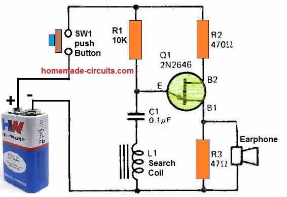
The circuit looks like an ordinary UJT oscillator without the search coil, however the circuit gets transformed into a metal detector due to the insertion of the search coil in series with the timing capacitor of the UJT.
When a metal is brought near the search coil, the impedance of the coil is changed which cause the frequency of the oscillator to change. This change of frequency is detected in the form of a varying tone over the earphone. The varying tone on the earphone allows the user to realize the presence of a metallic object at a close proximity of the search coil.
How to make the Search Coil
The search coil is a simple electromagnet which can be built by winding a choke coil over the center pillar of a laminated E-core assembly. The details of the coil can be found in this article.
2) Single Transistor BFO Metal Detector Circuit
The 2nd design below becomes a simple metal detector when it is coupled with a nearby radio receiver that serves as both a detector and an amplifier.
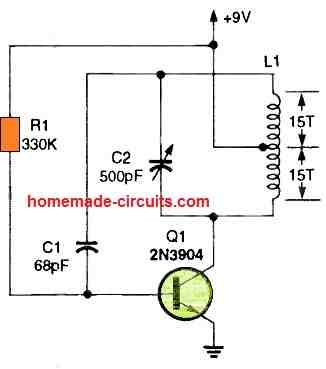
A 3 to 4-inch diameter plastic base or bobbin is wrapped tightly with 30 rounds of wire to create oscillator coil L1. A center tap is pulled after the 15th turn.
It becomes a search head or sensing coil when connected to the circuit via a three-wire connection.
If you want to use the circuit as a conventional ground-sweeping metal detector, you'll want to mount the search head or sensor at the lower end of a long pole made of wood or plastic.
The same circuits might be used to find army mines or hidden treasures that contain at least some metal.
The whole circuit might be kept in a compact container if you want to find metal pipes or wires hidden behind plastered, wood, or brick structures.
The metal detector circuit needs a metal body that will interfere with coil L1's electromagnetic field in order for it to function.
The encroaching item affects both the frequency of the field and the inductance value of L1.
Locating the metal object might be made easier with a battery-operated portable broadcast band radio moved closer to the locating circuit. It lets out a piercing cry as soon as it notices the change in frequency.
First, tune the radio to a local station so you can hear a low-frequency beat or fluttering coming from the speaker.
Next, adjust C1 to hear the radio's speaker produce a low-frequency beat or ping.
The beat note changes significantly if the detector circuit happens to be nearer to the hidden metal item.
3) Using a Single IC 4093
In the 3rd design I have explained a simple metal detector circuit having a decent sensitivity using a single CMOS IC 4093, as I have explained below.
How it Works
The circuit functioning may be understood with the following points:
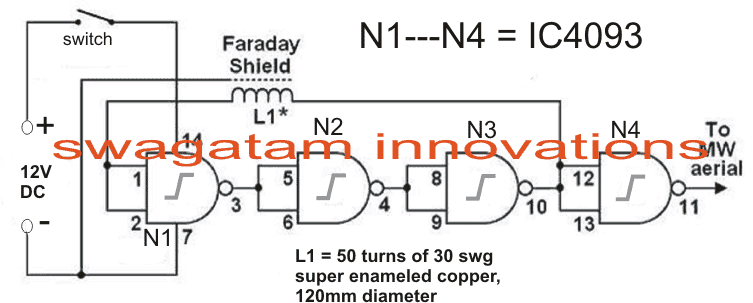
The proposed metal detector uses a 4093 quad Schmitt NAND IC and a search coil along with a switch and batteries for power.
A lead from IC1d pin 11 connects to MW radio aerial, or another process would be to warp around the radio. The BFO switch if present in the radio must be turned on.
The resistance of rapid change in voltage – known as reactance, delays the logic level at ICI pin 10 back to its input pins 1 and 2, and is further delayed through propagation delays within 4093 IC.
This entire process results into rapid oscillations of around 2 MHz, is picked up by a Medium Wave radio.
2 MHz is out of range for Medium Waves, but a MV radio can accept the harmonics of 2 MHz frequency. The process of winding of the coil is not complicated.
Coil Winding Specifications
The prototype uses 50 turns of 22 awg/30 swg (0.315 mm) enameled copper wire, wounded on a 4.7"/120 mm former, and then wrapped in an insulation tape.
The coil is then connected to 0V.A Faraday shield which is a tin foil acting as a wrapper around the coil. This process leaves a small gap and care should be taken so that the foil does not wrap the entire circumference of the coil. An insulation tape is again used to wrap the Faraday shield.
A connection can be established to the Faraday shield with a piece of stiff wire wrapper around the shield, before adding the tape.
An ideal scenario would be to wire the circuit with twin-core or microphone cable, and connect the screen to the Faraday shield.
How to Set up the Circuit
Setting up the metal detector involves switching on the MW radio to pick up a whistle on a harmonic of 2 MHz.
However to note, not all harmonic works best, only the one which suits need to be used. With a suitable harmonic and the metal will alter the tone of a whistle.
A metal detector detects a large coin at 80 to 90 mm, which is quote good for a BFO detector. It can even identify discrimination between ferrous and non-ferrous metals with the rise or fall in tone.
Submitted By: DhrubaJyoti Biswas
Circuit Diagram
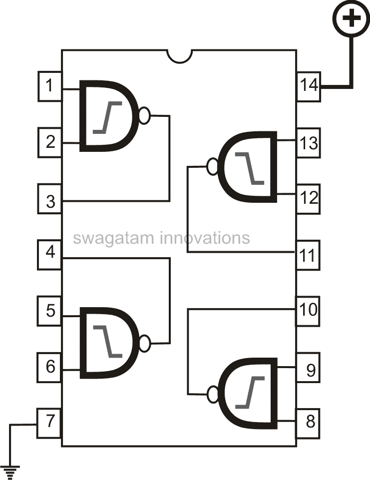
IC 4093 pinouts
4) Metal Detector using Magnetic Absorption
Behind the detection technology of this 4rth metal detector circuit is a sensor that identifies the existence of ferrous and non-ferrous metals by absorbing the magnetic energy.
This magnetic field is produced by an inductor which a part of a modified oscillator circuit. The moment a metal object is approached to the magnetic field, sufficient magnetic energy is absorbed to halt the oscillator.
Figure below depicts the Colpitt’s oscillator that fires around 70 kHz. Inductor L1 functions as a sensor due to the emitter resistor’s (R1) large value and eventually, the oscillator just works.
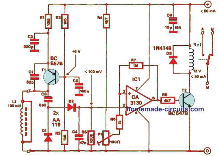
This is favourable because alternatively the losses in the regulated circuit will be reloaded by the transistor. D1 and D2 will rectify the oscillating output and the subsequent direct voltage is directly applied to the inverting input of Schmitt trigger IC1.
Once the voltage dips below the value at pin 3 which is represented by P1, the output will switch to a high, energizing the relay. We recommend constructing the detector on a PCB as shown in the figure below.
The actual purpose of inductor L1 was not to mount in on the PCB. In case the oscillator does not immediately start at whatever setting the P1 was engaged, you must bring down the value of R1.
Alternatively, if the oscillator continues detecting even when a metal object is held close to L1, the R1 value must be increased.
You need to start with the wiper of P1 to earth and control the preset so the relay does not operate at all. When you need a little more sensitivity, increase the wiper a tad more.
The energising of the relay principally dictates the current consumption and for most cases, it is not more than 50 mA.
5) LC Tuned Metal Detector
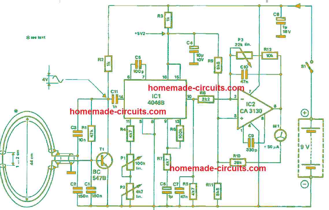
Unlike the metal detectors discussed above, this 5th concept works under the rule that the frequency of an LC oscillator varies when there is modified inductance. To make that happen, the inductor is approached with any type of metal detector.
The frequency change rate depends on the properties of the metal and on the frequency itself. If the latter is too high, a metal component will act like a shorted turn that brings down the inductance so that the frequency elevates.
In the event the frequency is substantially low for eddy-current losses to be neglected, we can then differentiate between ferrous and non-ferrous metals.
It will be quite challenging to make an oscillator frequency below 200 Hz. Due to that, the oscillator in the current circuit operates around 300 kHz. To make its inductance is quite simple and all you need is a single turn of a coaxial cable a depicted in the following figure.
How it Works
The LC tuned metal detector circuit is made up of an oscillator T1, a frequency-to-voltage converter IC1 and a BiMOS operational amplifier IC2. By employing a detector coil diameter of 400 mm, the values of capacitors C1 and C2 guarantee an oscillator frequency of 300 kHz. When smaller diameter coils are used, you will need more turns.
To supply the 4046B adequately, the oscillator signal strength must be around 400 mVππ. The phase comparator warrants that the internal phase-locked loop always locks at that level. At pin 10, the source follower input is supplied to a CA3130 where it is sufficiently amplified.
How to Set up
Conveniently, P1 sets the centre frequency of the phase-locked loop and the zero of the centre-zero microammeter. Using P2, you can make fine adjustments if the sensitivity of the opamp is high.
Moreover, P3 sets the sensitivity in the discussion which is attached in a negative feedback loop to the inverting input. Notice there is a positive feedback through the microammeter and R10 to the non-inverting input. When you choose a different resistance, it is important to modify the values of R9, R10 and R11 appropriately.
6) Using IC CS209
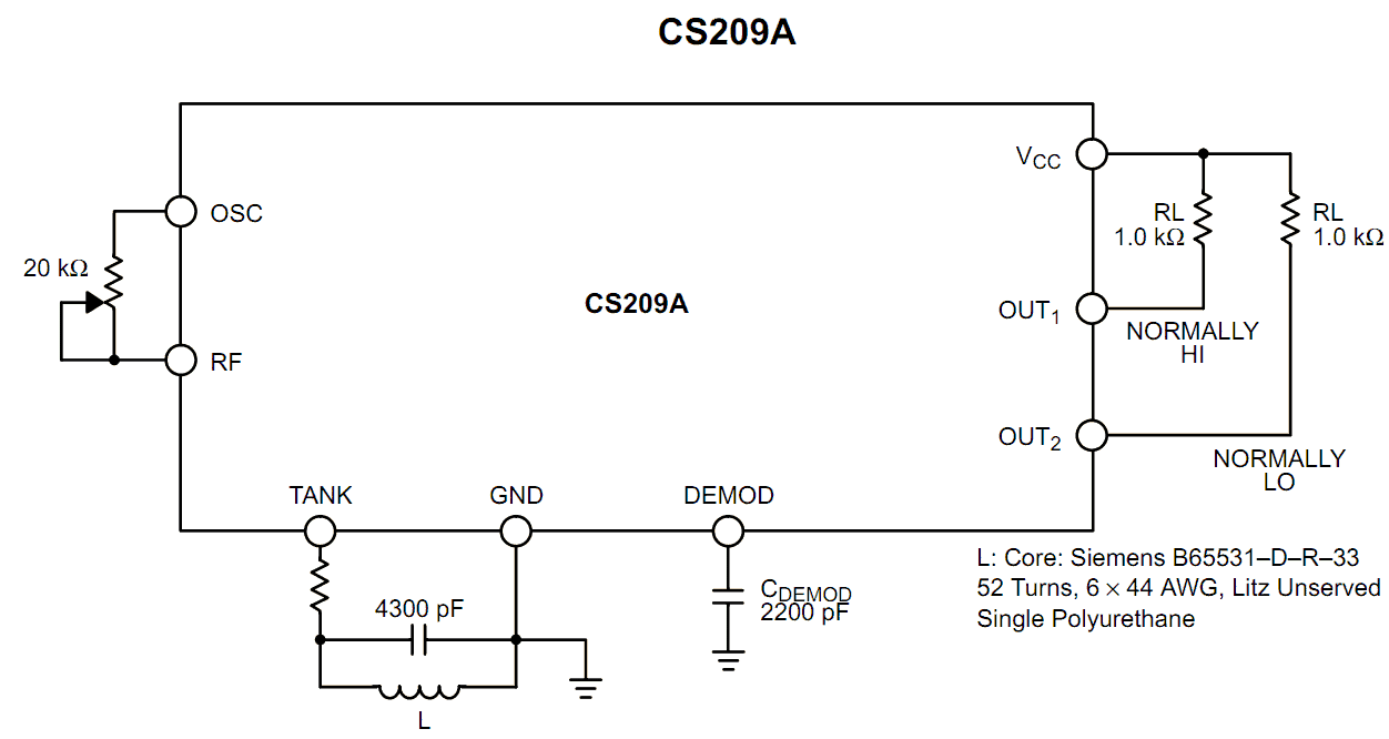
The principle of operation of our 6th metal detector circuit is quite basic yet very interesting. The detecting function is triggered by sensing the decrease in the Q level of the LC network associated with the circuit in the presence of a metal at a specified proximity level.
Basically the built-in oscillator of the IC CS209 is made functional with the inclusion of a parallel resonant LC tuned network in conjunction with a feedback resistor wired up with the OSC and RF pin outs.
The impedance of the tuned resonant network may be expected at the maximum level as long as the driving source frequency is equal to the resonant frequency of the LC circuit network.
On detecting the presence of a metallic object at a close proximity to the inductor sensor, the voltage amplitude of the LC network gradually begins to fall corresponding to the closeness of the metal to the inductor.
Due to the above factor when the oscillation frame of the chip drops and reaches a certain threshold level, triggers the position of the complementary outputs such that they change states.
The precise technical the operations may be understood as follows:
Referring to the figure, as soon as a metal object is detected at the inductor input, the capacitor connected to the DEMOD gets charged through an in built current source of 30 uA.
However during the detection process the above current gets deviated away from the capacitor proportionately with the generated negative bias on the LC network.
Therefore the charge from the capacitor is removed attached to DEMOD with every negative cycle generated across the LC network.
The DC voltage with ripple over the capacitor of the DEMOD is then directly referenced with an internal fixed 1.44 voltage level.
When the procedure forces the internal comparator to trip, it switches the transistor which introduces a 23.6 K Ohms in parallel to the given 4K8 resistor.
This resulting reference level then equals near about 1.2 volts which introduces some sort hysteresis in the circuit, and becomes ideally suited for preventing wrong or false triggering.
The feedback pot connected across the OSC and the RF is used for setting the detection range of the circuit.
Increasing the resistance of the pot, in course increases the range of detection and subsequently the tripping point of the outputs.
However the detection and the trip points may also be dependant on the LC configuration and the Q of the LC network.
How to Set up the Metal Detector Circuit
The proposed metal detector circuit may be set up initially by following the below described steps:
Position a metal object at relatively larger distance away from the inductor, assuming the Q of the LC to be at the maximum sensitivity and the distance to be within the allowable range provided by the Q factor of the inductor.
With this set up adjust the pot such that the outputs just shift states indicating the detection of the metal object.
Repeat the adjustment procedure by gradually increasing the distance until a suitable maximum sensitivity of the circuit is optimized.
Removing or displacing the metal manually should make the output of the circuit to revert states, confirming the perfect working of the circuit.
Though the circuit is able to detect metals within a range of 0.3 inches, the range may be suitably increased by increasing the Q of the inductor.
The Q factor is directly proportional with the sensitivity of the circuit and the degree of detection.
7) Metal Detector using Ordinary Components
This 7th metal detector simply employs all of the common components, as shown below. It utilizes a 2N2222 transistor and a couple of 741 ICs.
Even the detector coil is as simple as it can be! You just need to wind 8 turns of 22 SWG super enameled copper wire over a 9 inch diameter former.
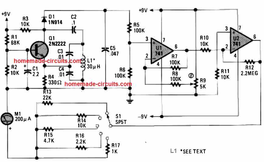
After finishing the winding, secure the coil using strapping or a strong adhesive and gently pull it off and remove from the former. Transistor Q1 works like the main component of a Colpitts oscillator. Diode D1 rectifies the frequency from the Colpitts oscillator to a certain varying DC.
Op amp U1 works like as a differential amplifier to zero the varying DC, and U2 is used to boost the signal over a 200 µA meter. To use the simple metal detector circuit, fine-tune the potentiometer until the meter M1 reaches at the midscaleof the dial.
As soon as a metal object such as gold, tooth fillings, etc come to a close proximity of the coil's field of view, small alterations in the amplitude of the frequency waves trigger changes on the meter reading. Switch S1 works like an attenuation or sensitivity selection switch.
8) Another Metal Detector Circuit using BFO Concept
The 8th metal detector principle discussed below is fairly well-known, as can be seen in the block diagram in Figure 1.
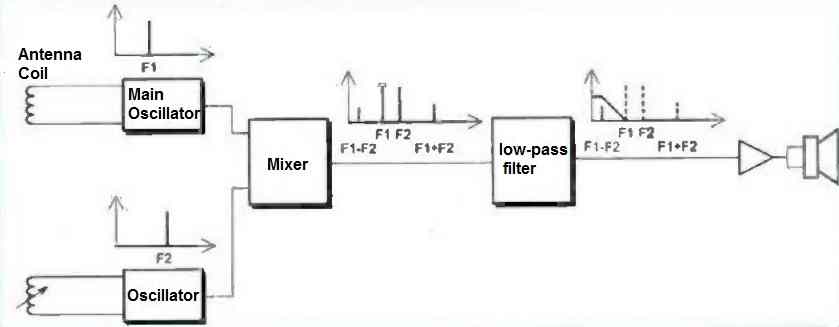
The detector is made up of a large coil acting as an antenna, which is coupled with a capacitor and an amplifier to form an LC oscillator. When the antenna coil approaches a metal mass, the resonance frequency of the LC oscillator is altered.
To detect this change in resonance, the signal from the main oscillator is mixed with that of a second oscillator tuned to a frequency very close and as stable as possible. The resulting signal contains the beat frequency of the two oscillators.
By tuning the secondary oscillator so that the beat frequency becomes audible, it is then easy to isolate the audible signal using a good filter, and then amplify it to drive a small audio headset. The frequency variations of the audio signal will immediately inform the operator of the proximity of a metal mass.
The human ear is capable of detecting very small variations in the frequency of the audible signal, making it easy to detect small metal fragments with such a device.
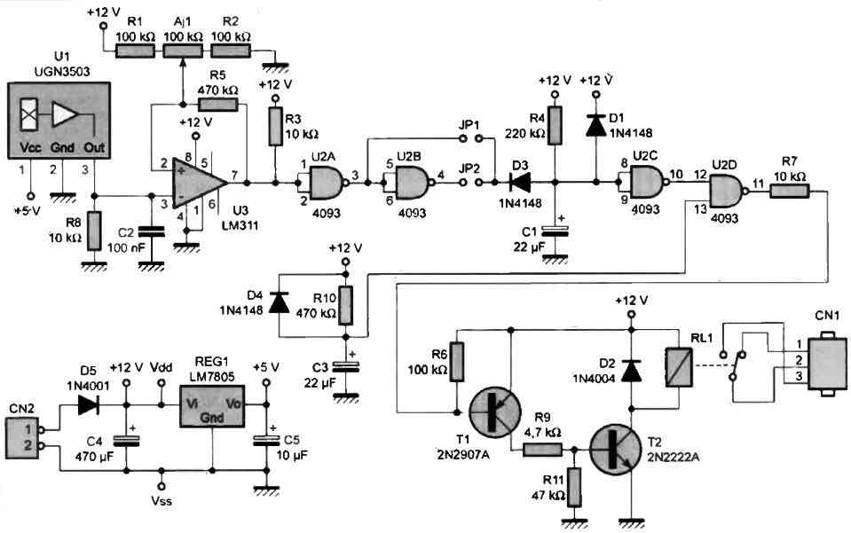
How the Circuit Works
The diagram of our setup is shown in figure 2. The main oscillator is centered around transistor T1. The operating frequency of this oscillator (F1) is set by C3, C1, and the antenna that will be connected to CN1.
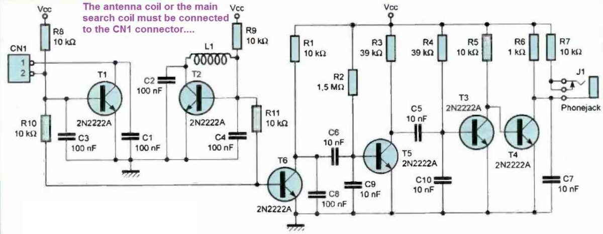
As for the secondary oscillator (frequency F2), it is centered around transistor T2, associated with C2, C4, and L1. Both oscillators will be tuned to a frequency close to 120 kHz.
Resistors R10 and R11 allow us to take the signals produced by the two oscillators and mix them at the base current of T6.
The alternating component of the voltage appearing across R1 is the result of the two mixed signals. If you observe the signal with an oscilloscope, you will see a signal with a frequency of 120 kHz modulated in amplitude at the beat frequency F3 = F1 - F2.
Capacitors C8, C6, and C9 will strongly filter the main frequency of the signal (120 kHz) to finally let only the low part of the spectrum pass through.
The signal obtained across R3 is already the audible signal we are interested in, and it only needs to be amplified through transistors T3 and T4.
The amplified signal will be used to drive an audio headset equipped with small speakers of 32 S2 via J1. Resistor R7 is used to limit the sound level of the signal imposed on the headphones.
We have not provided a sound level adjustment for this setup. If you wish, you can replace R7 with a 100 S2 resistor, after which you only need to mount a 10 k potentiometer in series with the headset.
Power Supply
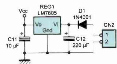
This detector can be powered by a small 9V battery connected to CN2, with diode D1 used to protect the setup against reverse polarity. We use a regulator (REG1) because the tuning frequency of the L/C oscillators is quite sensitive to changes in the power supply voltage.
Given that our setup operates by analyzing the frequency difference between the two oscillators, even slight changes in the power supply voltage would immediately be audible.
Therefore, we preferred to use an LM7805 regulator to spare you from this kind of inconvenience.
However, note that there is another important source of frequency drift in our setup. This is due to the environmental conditions of the L1 inductor that tunes the secondary oscillator.
Indeed, the impedance of this inductor is also sensitive to magnetic fields. Special precautions must be taken during its implementation, as we will see later.
PCB Designs
The printed circuit board design for this setup can be seen in Figure 3. The associated layout view is reproduced in Figure 4.
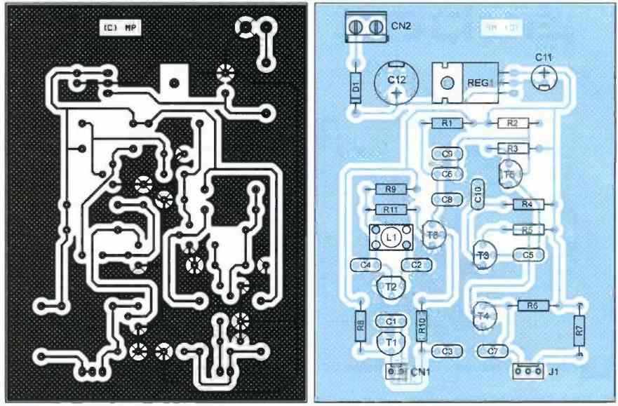
Most of the pads will be drilled using a 0.8mm diameter drill bit. For the pads of the connectors, diode D1, and regulator REG1, a 1mm diameter drill bit will be needed.
Apart from the coil winding, there are no particular difficulties in building this circuit. However, pay attention to the orientation of the transistors and capacitors C11 and C12. The selected components are common and should be readily available at your usual supplier.
How to Construct the Antenna Coil
Now let's move on to the coil winding. The antenna coil must be constructed with great care, as its characteristics directly affect the sensitivity of the circuit.
To do this, you will need to find a cylindrical support with a diameter of around 12 cm (10 cm to 15 cm can also be suitable).
The support used to make this coil must be chosen from a material that does not interfere with magnetic fields (plastic is an excellent choice). For example, the base of certain CD boxes may be suitable (boxes of 25 stacked CDs).
To make the antenna, you will need to wind 10 turns of enamelled wire (wire diameter: 0.2 mm to 0.3 mm), well aligned and tightly packed. Once the winding is done, the enamelled wire must be immobilized with glue (hot glue, for example).
As the enameled wire is quite fragile, it is preferable to solder a connector to the ends of the coil wire (don't forget to scratch the enamel with sandpaper to ensure direct contact with the copper).
In this way, you can easily change the position of the antenna without worrying about breaking the enameled wire by manipulating the coil.
How to Construct the Oscillator Coil L1
The second coil (L1 on the diagram) will be mounted directly on the printed circuit board. It will be made using a winding support with a diameter of 6.5 mm and a ferrite core to allow tuning of the secondary oscillator's frequency.
Initially, you will need to wind 120 to 130 turns of enamelled wire (wire diameter: also 0.2 mm to 0.3 mm). Later, as we will see in the next paragraph, you will remove turns until you achieve a very close frequency match between the two oscillators.
How to Setup and Tune the L1 Coil
To adjust the L1 coil, proceed as follows. Connect the antenna and headphones to the circuit and turn on the device.
Be careful to place the antenna more than 50 cm away from any metal mass and also keep it away from the L1 coil during the entire tuning phase. Initially, place the ferrite core of L1 at the top.
Using a non-magnetic screwdriver (fully plastic), slowly submerge the core in the middle of the turns until a sound signal is heard in the headphones.
If you cannot obtain this sound signal when moving the core from one end to the other, you will need to remove 10 turns from the L1 coil.
Then, you will need to repeat the L1 tuning process until a sound signal finally appears (otherwise remove another 10 turns, etc.).
For your information, if you use the same antenna support as us (10 turns on a diameter of 12.5 cm), the L1 coil should have 100 turns.
Once the tuning of L1 is complete, you can immobilize the wire with glue (to maintain its mechanical characteristics).
It should be added that this circuit is very tolerant as the working frequency of the L/C oscillators can range from 50 kHz to 200 kHz. Therefore, you should not experience significant difficulties in making your prototype work.
How to Test
Once the adjustment of L1 is complete, the use of this detector is very simple. Adjust the ferrite core of L1 so that the frequency of the sound signal is very low.
Then, bring a coin close to the antenna to check that the frequency of the sound signal increases as the distance between the coin and the antenna decreases. If you notice that the frequency of the sound signal decreases instead of increasing, it means that the tuning frequency of the secondary oscillator is the highest (F1 - F2 < 0).
In this case, simply move the magnetic core until the beat frequency is canceled, then continue to move the core in the same direction so that the sound signal reappears (but with F1 - F2 > 0 this time).
Don't forget that there can be coupling between the antenna coil and L1. Make sure to maintain a distance of at least 20 cm between the setup and the antenna.
Furthermore, the relative position of the setup and the antenna should be kept as stable as possible (so that the residual coupling remains constant and does not cause a slight drift in the beat frequency, which could decrease the sensitivity of the setup).
It is therefore preferable to fix it (in a box) on the handle of the detector.
In this case, add a switch in series with the power supply, as we did not plan one on the printed circuit. Also, provide access to the bolt to adjust the position of the L1 coil core.
Indeed, you will certainly have to adjust the tuning frequency from time to time, as our setup does not aim to compete with professional equipment (the effect of external temperature is quite sensitive).
In practice, this is not too problematic because the frequency of the sound signal does not drift suddenly. Your ear will be able to distinguish between the slow variation of the reference oscillator and the abrupt variation of the beat frequency due to the appearance of a metallic object in proximity to the antenna.
When you go out in the field, make sure to bring a non-magnetic screwdriver with you for adjusting the L1 core if needed.
We will conclude this article with an important warning. It is important to know that the use of a metal detector is regulated (both in public and private domains) and requires authorization from the prefecture. Readers are strongly encouraged to inquire about this matter.
9) Crystal Controlled Highly Sensitive Metal Detector Circuit
The block diagram of the 9th metal detector circuit setup shown in Figure 1 below, reveals two oscillators. One produces a fixed frequency of 500 kHz (F1), while the other generates a nearby frequency (F2).
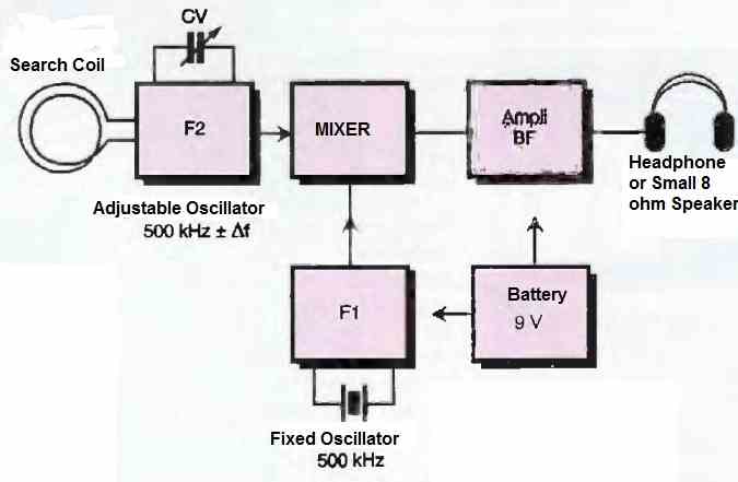
The frequency of the latter can be adjusted using a variable capacitor and modified by the presence of nearby metallic elements close to the detection coil.
After mixing, the two frequencies produce a low-frequency audible wave that allows the presence or absence of a metallic object to be detected.
How the Circuit Works
Figure 2 below introduces us to the circuit diagram of the high sensitivity metal detector. Its simple architecture is based on the utilization of two integrated circuits.
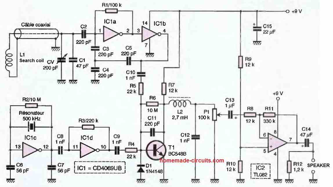
One is a CMOS, the 4069UB (unbuffered), and the other is a linear circuit, the TL082, of which only one amplifier is utilized to drive a layer or a small loudspeaker.
The fixed oscillator is realized by IC1c, mounted in the classical manner for this function. The 500 kHz resonator stabilizes the frequency.
The sinusoidal signal, available at pin 12, is fed into the input of IC1D as a buffer. At its output, we obtain a square wave signal rich in harmonics.
The variable oscillator is built around the gates IC1A and IC1B. It is a relaxation oscillator whose central frequency is determined by the LC circuit: the external coil and the variable capacitor in parallel with the series/parallel capacitors C1 and C5.
This arrangement produces a superb sinusoidal waveform of 14V peak-to-peak across the terminals of L1. The two signals F1 and F2 are applied to the base of T1 through the two networks C10/R5 and C9/R4, with values sufficient to allow for current drive.
The diode D1 prevents the signal from being aligned towards a negative value, which would no longer allow proper operation of T1.
The mixing of the two current flows F1 and F2 in the base junction of T1 results in a low-frequency voltage with a parabolic shape at the collector.
This voltage is rid of high-frequency components by the low-pass circuit L2/C12. The amplifier IC2 allows for comfortable listening after adjustment with the potentiometer P1.
Construction
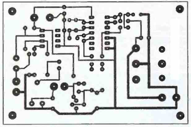
Figure 3 below shows the design of the printed circuit board at a 1:1 scale, and the next Figure 4 illustrates the component placement. There are no particular difficulties involved.
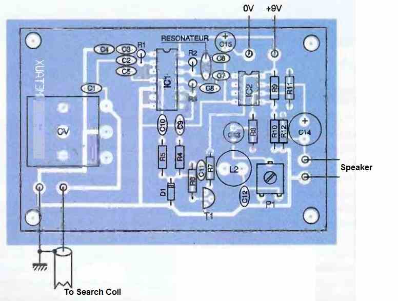
For the wiring, start with the flat resistors, the 1N4148 diode, and the integrated circuits, making sure to align them correctly. Finish by placing the standing components.
The variable capacitor is a model obtained from a longwave receiver (200 pF). However, we have also included C1 (47 uF) in parallel, which allows us to adjust the value of Cv as needed.
Note that it is also possible to parallelize the two sections of a low-value variable capacitor by bridging the free connection of Cy with the nearby trace.
The drilling of the 4 holes should be done in such a way that the components fit snugly. However, it is advisable to reinforce them with a bit of epoxy adhesive (such as Araldite), as well as the battery mounts.
How to Build the Search Coil
This highly sensitive search coil inductor was made by winding 36 turns of 0.4 mm or 0.5 mm thick enameled copper wire with a diameter of 100 mm. We used a tin can as a support.
Secure it with adhesive tape. The connecting cable is a 75-ohm coaxial cable with approximately 100 pF per meter, and it has a length of one meter as well.
We have taken into account this parallel capacitance in the calculation of the oscillator.
How to Test
Upon powering on, you will hear a more or less high-pitched whistling sound. Adjust the tone of the low-frequency signal by manipulating the variable capacitor.
It is possible to observe the effect of discrimination that can be achieved. Set the variable capacitor to produce a sound of approximately 1000 Hz.
Bringing a piece of copper close to the detector will increase the frequency. Adjust it, for the same 1000 Hz signal, on the other side of zero hertz.
This time, the proximity of the copper piece will cause the low-frequency to decrease.
The detection range varies from 1 to 10 cm depending on the mass of the metal. With

Questions & Answers
Hola, se ve interesante, tengo la necesidad de detectar elementos como agujas aproximadamente a 30cm, es posible?
Hey, thanks, 30cm looks too high for detecting a needle, not possible using the above concepts…
I want to ensure the deep of my target … can you support.
Hail metal detector I want to just drop the gold and the silver and if it gets radius and if you can be guided, thank you
Hi thanks for the circuits, I’m looking for a simple one that can be used for underwater detecting (with led indication ) ,I does not need to be so sensitive a coin at 6-7 cm is enough thanks for replying
Hello, and a robot that can explore up to 2 meters, can a robot be designed that can run on a car battery?
Yes, a robot can be designed using car battery, but it will become very heavy…
Hi, I think the 1) concept looks promising and can be tried for your application…
Let me know what you think about it?
hello, I am new to this link, maybe you can help me with a metal detector that I am using, a chip from the 4000 (CD40106) would like to configure it properly so that it works correctly, what other components to add so that it has good depth and metal discrimination
the cd40106 has 6 inverter gates, just like they do with the CD4093, by joining the two inputs of each NAND gate of the CD4096, they are making it become an inverter. For such a configuration to work, they must always place the inductive element in such a way that the ends of the coil have opposite polarity, that is, there must be an odd number of inverter elements between the ends of the coil, it can be 1, 3, or 5
Victor, I do not have this circuit with me at the moment, if I happen to find it I will surely post it in the above article….
Hello
I want to build a metal detector that can detect a coin at a depth of more than 80 cm.
Hello, 80cm is too large, I do not have a circuit which can detect metal at this distance.
I have the circuit diagram and I want you to comment on it as an engineer
If your metal detector circuit is complex and has many stages then it may not be possible for me to review it, due to lack of time.
Please give me an email address so I can send it to you.
Thank you
you can send it to
homemadecircuits
@gmail.com
Ok. Thank you
I checked the diagram which you sent in my email, however the diagram is too big with many stages, so it is not possible for me to assess it due to lack of time…
I want to tune the RX winding of a metal detector coil, against the TX winding, by setting the windings to Zero Voltage, thus nulling the detector coil. I heard that one uses an oscillator circuit to do this, however I do not have a Frequency Meter nor do I possess a Oscilliscope Scope, but I have a Voltage-Ohm meter and a LCD meter. Is there a circuit I can build to do this?
You can build a good frequency meter using some discrete components as explained in the following article: You can try the IC 555 version which is the simplest one:
https://www.homemade-circuits.com/simple-frequency-meter-circuits-analogue-designs/
Unable to locate the CS209A used in your simple metal detector. What other IC could be used as a substitute? Would the pinouts be the same? Thanks for your assistance.
You can try any of the following alternatives:
https://media.digikey.com/pdf/Data%20Sheets/ST%20Microelectronics%20PDFS/TDA0161.pdf
https://www.homemade-circuits.com/stud-finder-circuit-find-hidden-metals-inside-walls/
I am looking for a metal detector circuit with coil dia around 200 mm and detection of small nails and screws (1.5 mm dia) from a max distance of 25 or 30 mm
Please suggest
I have a few good schematics with me, will surely publish it in the coming days.
سلام ، لطفا ولتاژ خازن. هارو هم به همراه ظرفیت ذکر کنید ، ممنون
The general rule is, all capacitor voltage ratings must be ideally 2 times the supply input voltage value, or higher.
ممنون