The following post discusses a simple ion detector circuit which can be used for detecting positive and negative ions generated by high voltage circuits. This device can be also used for detecting static discharges in the atmosphere. Static discharge is normally emitted by high voltage sources such as sparks, arcing etc. It may be also generated by human skin if it happens to rub with plastic objects such as comb, rexine furniture, or silk curtains.
Static Electricity can be Dangerous to FETs and CMOS ICs
Many of the modern high-impedance, solid-state gadgets may be vulnerable to electrostatic discharge.
This is particularly true for FET and CMOS semiconductors, which are susceptible to electrostatic discharge damage (ESD).
To eliminate destruction while touching, mounting, and interacting with these delicate components, the majority of manufacturers provide grounding instructions.
Before installing or using any of these vulnerable systems and devices, a search-and-destroy (discharge) strategy could be employed to effectively locate problem areas or hazardous regions that must be neutralized.
For this kind of safety operations we can use the proposed electronic static or ion detector circuit.
Another excellent use of this ion indicator circuit is for sensing and indicating ions generated by a ionizer circuit.
If you have built a negative ion generator circuit published in this website, you can effectively use the proposed ion detector circuit to detect the ions generated by the ionizer circuit.
How is Static Electricity Produced
Before we investigate our ion detector circuitry, let's quickly review the characteristics of an ion or static electricity. Ions are atoms that have an electrical charge.
Positively charged ions lack electrons, while negatively charged ions have an excess of electrons.
By supplying electrons to a material or taking electrons away from a material, static electricity is produced.
The charge can increase to an extremely high potential if the material is adequately insulated and the atmosphere is very dry.
The potential difference across an individual can increase by several thousand volts while the person is moving out from a furniture or strolling across a carpeted floor. This amount of potential difference developed across the person is sufficient to destroy delicate CMOS based electronics.
Circuit Description
Referring to the following figure, the 3 transistor high gain detector stages determines the relative intensity of this static charge. Simultaneously, the circuit also identifies the polarity of the static charge.
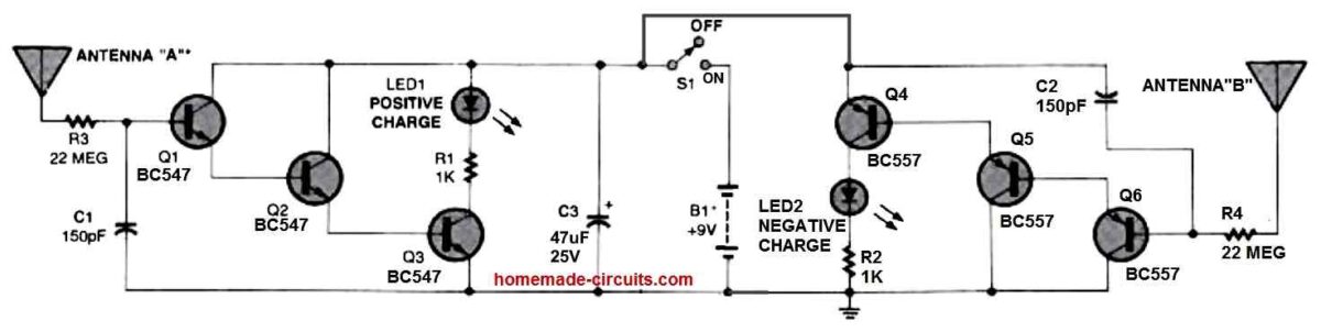
In essence, the detector consists of two circuits, one of which can detect positive ions and the other which can detect negative ions.
Three BC547 NPN transistors are used in the positive ion detector circuit. These transistors are configured in the form of a high input impedance Darlington DC amplifier circuit.
When antenna "A" detects a positive ion or a positive static charge, LED1 displays the relative output. Three BC557 PNP transistors are configured to detect negative input charge.
These can be seen configured in the other half of the circuit. The relative output of the negative charge is displayed by LED 2.
Capacitors C1 and C2 help prevent AC frequencies from entering the amplifier circuitry. Resistors R3 and R4 are positioned to restrict the input current of the amplifier.
The circuit should ideally be housed inside a metal box. The battery negative must be electrically hooked up with the body of the enclosure.
This will allow the ion detector circuit to operate most effectively. The antennas could be an ordinary length of flexible wire. Both the shown antennas should be placed such that they are parallel to one another and facing towards the same direction. Make sure the antennas never come into contact with each other or with the metal enclosure.
How to Test
- The cabinet must be at ground potential for using and testing the static detector. Meaning, before testing the circuit, hold the metal box firmly in your hand or hook it up with a good earthing ground.
- Next, run a plastic comb through your hairs and quickly bring it close to the antennae. As the comb is brought near to the antenna, one of the LEDs will start illuminating brightly.
- Make another test by walking over a carpeted floor holding the detector in your hand. At the same time point the antennas towards stationary metallic objects without touching it.
- Check the glow on the LEDs. One of them will illuminate. Next, ground the metal object by touching it to some earthing. Now repeat the procedure.
- Now the LEDs will remain shut off indicating no charge, if the static charge on the metal is fully neutralized through earthing.
Testing Static Charge with Electrometer
The device which can detect static charge is called an electrometer and is fairly sensitive to static charges.
I always use this meter before working with CMOS ICs or sensitive MOSFETs on PCBs. This is to to ensure there are no static electricity hanging around on my work bench, PCB, or on my hands, which could otherwise easily destroy these sensitive device almost instantly.
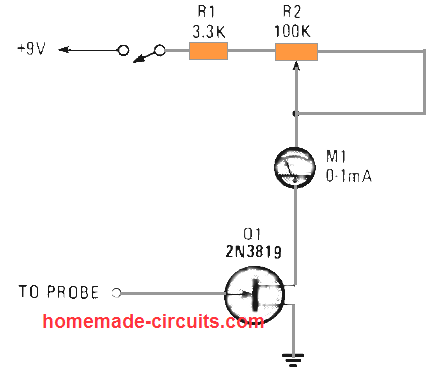
This electrometer is an electrical device that detects and shows the intensity of an electric charge or electrical potential difference.
The circuit can be powered with a 9V battery, and when the probe is brought near a possible electrostatic charged surface, the meter needle will deflect, indicating the presence of the static charge.
The volume of static charge is indicated over an ammeter and the JFET could be a 2N3814 or similar. The meter can be a 0-1 mA device; in case you find this type of meter is not adequately sensitive to suit your needs, you can replace it with a more sensitive low current meter.
The potentiometer is tweaked in order that the needle indicates 1 mA in the absence of a static charge around the probe. As soon as the probe is introduced sufficiently near to a charge, the meter needle must decrease towards 0 mA.
To examine whether or not your CMOS device storage box may be devoid of static charge, touch the electrometer probe directly into box. If you find the meter needle unmoved from the full scale 1 mA level, you can be assured that the box is free from static electricity.
Using IC 555 for Detecting Static Charge
A strong static electricity could destroy your IC RAM or other static-sensitive devices such as MOSFETs. The next circuit is really straightforward. This makes use of just 7 parts, along with a 555 oscillator/timer. Additionally, it works with a FET rigged like a "vision" to identify static-charge deposits.
As soon as the antenna is held alongside a high-voltage source, it decreases the 555's pulse frequency. You can observe the results through the flashing ON/OFF rate of the two LED's. I simply do not advise the use of a CMOS 555, since in that case it itself would be vulnerable to the static field and die quickly.
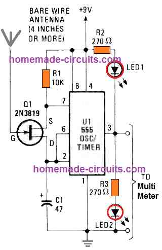
To verify if your IC 555 static charge detector actually works, try bringing the antenna very near to a television screen. You may quickly start seeing the LED flashing slowing down.
In order to reset the circuit, just short the antenna wire of the circuit to any ground wire of the circuit or a large metal plate, a few times. This must allow the LED flash rate return to fast rate, which is the normal rate in the absence of a static charge.
You can use this LED electrometer with a multi-meter for higher precision readings. The circuit really is easy, it is extremely sensitive to high voltage static emissions. All the parts are accessible at the local Radio Shack store.
The current consumption is so small that the circuit can easily work for a few hours without showing any abnormal effects.


Questions & Answers
Hello dear engineer,
I built this circuit, but I wanted to use it as a gold detector to find negative ions in nature — it didn’t work.
Could you please introduce a few practical ion-based gold detector circuits with a depth of around 5 meters?
I sincerely thank you
Hello Naser,
Ion-based gold detector circuit may not be feasible, or may be extremely inaccurate. The ones which are available online could be just scams.
The best possible option to detect gold would be to use BFO type metal detector:
https://www.homemade-circuits.com/how-to-make-simple-metal-detector/
https://www.homemade-circuits.com/deep-soil-metal-detector-circuit-ground/
Hi!
Thank you for making all these wonderful ideas available!
But… I have a problem. Transistor Q4 BC557 in the Ion Detector Circuit gets very hot and blows out after a few seconds. Have checked all soldering, layout and component placement several times.
Do you have any idea about what I could have missed or overlooked?
TIA!
Marie Hansen
Thank you very much for your feedback, and Glad you liked the ideas.
I checked the circuit diagram and I could not find any problems with the Q4 configuration. Please check the R2 value make sure it is rated at 1K, or it could be just that your BC557 is faulty.