In this post I will comprehensively explain how to use any opamp as a comparator in a circuit for comparing a input differentials and producing the corresponding outputs.
What is an Op amp Comparator
We've been using an op amp IC probably since we started learning electronics, I am referring to this wonderful little IC 741, through which virtually any comparator based circuit designing becomes feasible.
Here we are discussing one of the simple application circuits of this IC where it is being configured as a comparator, no surprise the following applications can be modified in numerous different ways as per the user preference.
As the name suggests, opamp comparator refers to the function of comparing between a particular set of parameters or may be just a couple of magnitudes as in the case.
Since in electronics we are primarily dealing with voltages and currents, these factors become the sole agents and are used for operating or regulating or controlling the various components involved.
In the proposed op amp comparator design, basically two different voltage levels are used at the input pins for comparing them, as shown in the below diagram.
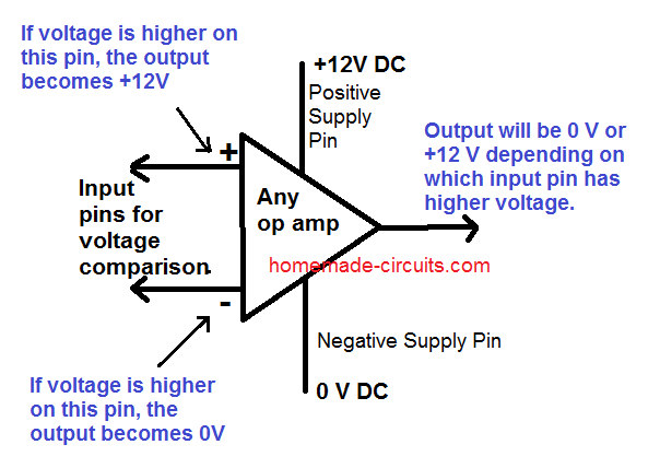
The two input pins of an op amp are called the inverting (with a minus sign) and the non-inverting pin (with a plus sign) become the sensing inputs of the op amp.
When used as a comparator, one of the pins out of the two is applied with a fixed reference voltage while the other pin is fed with the voltage whose level needs to be monitored, as shown below.
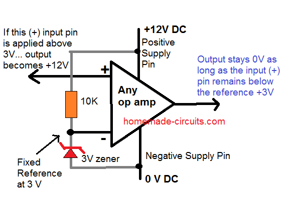
The monitoring of the above voltage is done with reference to the fixed voltage that's been applied to the other complementary pin.
Therefore if the voltage which is to be monitored goes above or falls below the fixed reference threshold voltage, the output reverts state or changes its original condition or changes its output voltage polarity.
Video Demo
How an Opamp Comparator Works
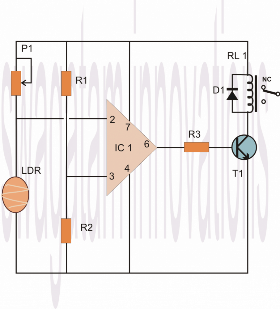
Let's analyze the above explanation by studying the following example circuit of a light sensor switch.
Looking at the circuit diagram we find the circuit configured in the following way:
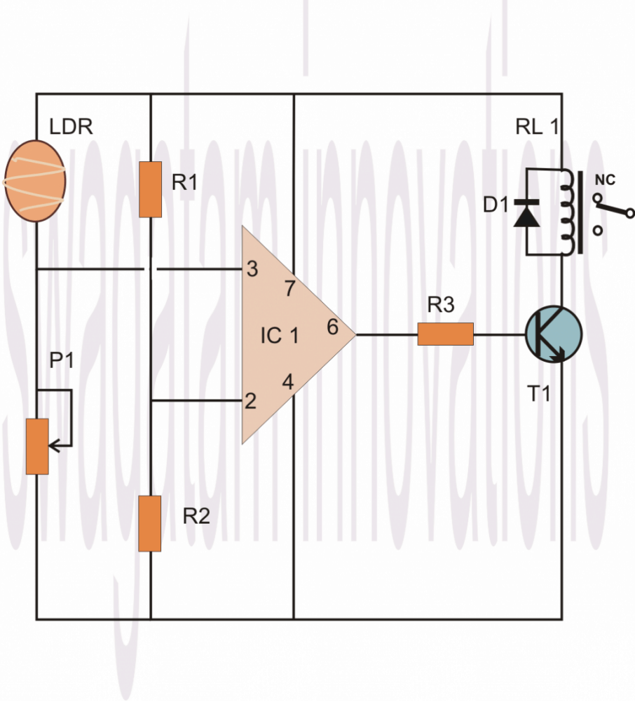
We can see that the Pin #7 of the opamp which is the +supply pin is connected to the positive rail, similarly its pin #4 which is the negative supply pin is connected to the negative or rather the zero supply rail of the power supply.
The above couple of pin connections powers the IC so that it can carry on with its intended functions.
Now as discussed earlier, pin #2 of the IC is connected at the junction of two resistors whose ends are connected to the power supply positive and negative rails.
This arrangement of the resistors is called a potential divider, meaning the potential or the voltage level at the junction of these resistors will be approximately the half of the supply voltage, so if the supply voltage is 12, the junction of the potential divider network will be 6 volts and so on.
If the supply voltage is well regulated, the above voltage level will also be well fixed and therefore can be used as the reference voltage for the pin #2.
Therefore referring to the junction voltage of the resistors R1/R2, this voltage becomes the reference voltage at pin #2 which means the IC will monitor and respond to any voltage that might go above this level.
The sensing voltage which is to be monitored is applied to pin #3 of the IC, in our example it is via an LDR. The pin #3 is connected at the junction of the LDR pin and a preset terminal.
That means this junction again becomes a potential divider, whose voltage level this time is not fixed because the LDR value cannot be fixed and will vary with the ambient light conditions.
Now suppose you want the circuit to sense the LDR value at some point just around when dusk falls, you adjust the preset such that the voltage at pin #3 or at the junction of the LDR and the preset just crosses above the 6V mark.
When this happens the value rises above the fixed reference at pin #2, this informs the IC about the sense voltage rising above the reference voltage at pin #2, this instantly reverts the output of the IC which changes to positive from its initial zero voltage position.
The above change in the state of the IC from zero to positive, triggers the relay driver stage which switches ON the load or the lights which might be connected to the relevant contacts of the relay.
Remember, the values of the resistors connected to pin #2 may also be altered for altering the sensing threshold of pin #3, so they are all inter-depended, giving you a wide angle of variation of the circuit parameters.
Another feature of the R1 and R2 is that it avoids the need of using a dual polarity power supply making the involved configuration very simple and neat.
Interchanging the Sensing Parameter with Adjustment Parameter
As shown below, the above explained operation response can be just reversed by interchanging the input pin positions of the IC or, by considering another option where we only inter-change the positions of the LDR and the preset.
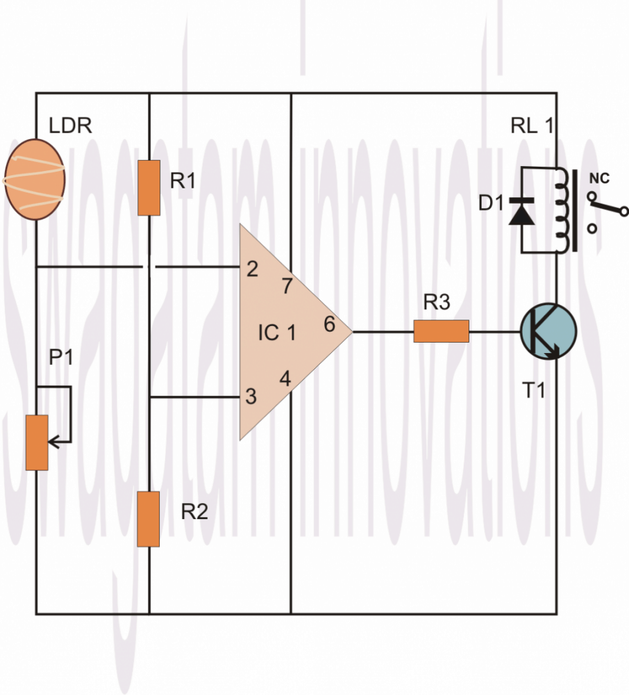
THis is how any basic opamp behaves when it is configured as a comparator.
To summarize we can say that in any opamp based compartaor, the following operations take place:
Practical Example#1
1) When the inverting pin (-) is applied a fixed voltage reference, and the non-inverting (+) input pin is subjected to an altering sensing volatge, the output of the opamp remains 0V or negative as long as the (+) pin voltage stays below the (-) refernce pin voltage level.
Alternately as soon as the (+) pin volatge goes higher than the (-) voltage, the output quickly turns positive supply DC level.
Example#2
1) Conversely, when the non-inverting pin (+) is applied a fixed voltage reference, and the inverting (-) input pin is subjected to an altering sensing voltage, the output of the opamp remains supply DC level or positive as long as the (-) pin voltage stays below the (+) refernce pin voltage level.
Alternately as soon as the (-) pin voltage goes higher than the (+) voltage, the output quickly turns negative or switches OFF to 0V.
Basic Comparator Working
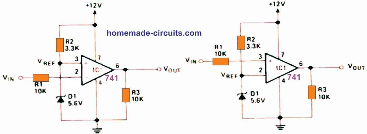
The circuit in the below figure operates in a relatively straightforward manner: The combination of R2 and Zener diode D1 produces a fixed reference voltage (VREF). It is applied straight to the op-non-inverting amp's input terminal, pin 3. Via the current limiting resistor R1, the input or test voltage VIN is connected to the inverting input terminal (pin 2). When VIN is less than VREF, the op amp output is high (to positive saturation), but when VIN is greater than VREF, the output is low (to negative saturation).
Op amp Comparator with High Voltage Input
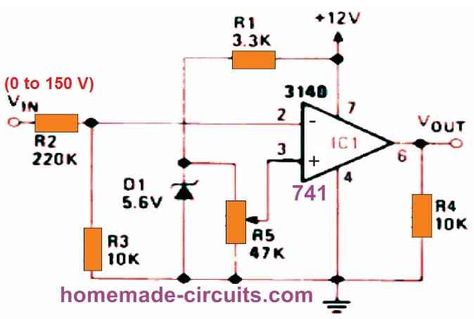
As shown in the below figure, using a VOLTAGE DIVIDER, we can utilize a voltage comparator to provide high-value, variable voltage triggering. There is no regenerative switching in this circuit.
Op Amp Comparator with High Value Input, Regenerative Switching
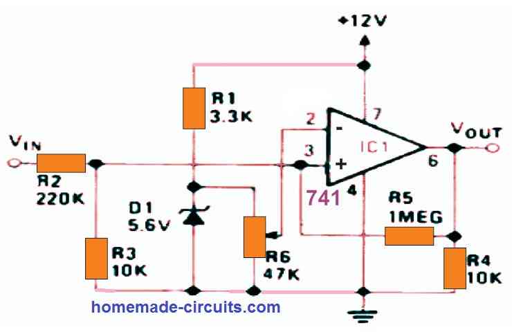
The next circuit, like the previous one, provides high-value, variable-voltage input switching (0 to 150 V). It has regenerative switching capabilities.
Op Amp Comparator as Over Current Indicator
When the load current reaches a value defined by R6, the output turns high to indicate an over current situation. By inverting the connections to IC1's pins 2 and 3, the output will go low to indicate an over-current situation.
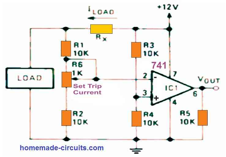
The diagram below demonstrates how a comparator circuit may be configured to operate as an over-current switch, producing a high output when the load current exceeds a given value - which you can set using potentiometer R6. Current sensing resistor RX is set such that it drops around 100 millivolts at the appropriate trip point. As a result, a fixed reference voltage equal to 1/2 the supply voltage is provided to pin 3 of the op amp through the voltage divider comprised of R3 and R4. Pin 2 receives a similar but current-dependent voltage through Rx, R1, R6, and R2.
In fact, the two sets of components form a Wheatstone bridge, with one side supplying pin 3 and the other supplying pin 2, and the op-amp serving as a bridge-balance detector. As a result, the circuit's trip points are unaffected by fluctuations in supply voltage but are very sensitive to changes in load current.


Questions & Answers
the pwm system is in plce already, many thanks, jb
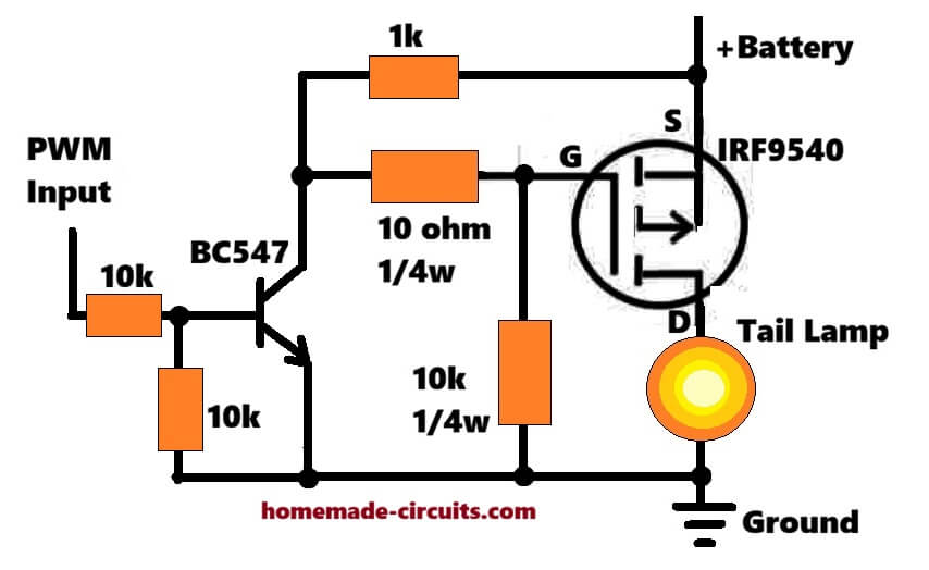
I think it can be implemented using a MOSFET/BJT circuit as shown in the following diagram, if you think comparator is required, please specify its configuration, I will try to draw it accordingly:
if this will identify when the pwm is high and then power the led (tail lamp in diagram) that will be great, will try it out—many thanks
Sure, you can try it…This circuit will keep the lamp brightness low as long as the pwm is 25%, and then increase it to full brightness when the pwm becomes 100%.
I assume you mean OFF until the PWM is >>25?
I am not sure how your PWM works, I am assuming it outputs 25% PWM under normal conditions, and 100% PWM when brakes are applied, so the circuit I suggested will handle these inputs perfectly for the lamp, as explained by me above.
thanks for the clarification, will try it out!
Useful – but be careful – see:
https://www.analog.com/media/en/analog-dialogue/raqs/raq-issue-11.pdf
https://www.analog.com/media/en/technical-documentation/application-notes/AN-849.pdf
https://wiki.analog.com/university/courses/electronics/electronics-lab-opamp-comparator
https://www.analog.com/en/resources/analog-dialogue/articles/amplifiers-as-comparators.html
Thank you very much for the useful information.
So here’s the all the issues I am facing right now
1. The voltage is floating in all the components in the circuit
2. Bc557 is not functioning as puch to on function
3. Getting 1.5~1.4 voltage at leds terminal but the led is not on
4. Getting 12v at pin7 and pin4 of the ic but ic is not responding
5. I have Checked twice the connection and all the connection is right
These are all the issues I am facing right now
Please try the following setup.
Move the preset up/down, the LED should illuminate and shut-off alternately at a particular point on the preset.
https://www.homemade-circuits.com/wp-content/uploads/2024/04/op-amp-test-jig.jpg
This will confirm whether your iC is good or bad.
After turning fully upside the lower led which is connected to the 1k resistor was on and after turning fully downside the led which is connected to the pin6 was not on and also the second led was off ! I am giving 18v to the circuit and there is 13.2v at the second led (when it’s on) and 1v at first led !
You must use 12v, not 18V, at 18V the 741 IC can burn.
Both LEDs are connected in series so both will turn ON/OFF together, not one by one.
Both the LEDs must turn ON and OFF at a “sharp” particular point of the preset rotation, not fully upwards or fully downwards.
Please change the IC and test again with 12V supply.
Sir listen can you make this circuit with my requirements and ship it to me please because of it I can find out my mistake more accurately i will pay the shipping charges please ?
Neeraj, Sorry, that may not be possible for me either.
Same nothing changed now with the 12v and I got 7v at the second led and first led didn’t turned on now at the sharp point it get turned on but the issue is same as before one more thing the second led which was lighted up now it’s was dimm means the led was not on its full potential
Neeraj, in that case I cannot understand your circuit problem because I cannot check what’s wrong with your connections or parts.
So which circuit should I follow to check the ic ? 741!
Please use the same circuit which I discussed in my previous comment.
Connect its pin2 to ground via 1k resistor, adjust the preset somewhere midway. Press the push button to latch the ic. Then manually connect pin2 with the positive rail momentarily, if the latch breaks, your ic is good. Repeat the procedure a few times to confirm the results.
https://www.homemade-circuits.com/wp-content/uploads/2024/02/latch-circuit-using-741.jpg
So I will work on this circuit and for checking the ic I will connect pin 2 of the ic with positive rail and remove the 1k resistor between pin2 to ground just for momentarily okay?
No, 1k will remain connected to ground as it is, in rhis position just touch pin2 with positive just for a second, and remove. This should break the latch.
Then press the button again to latch the circuit and again touch pin2 to positive to break the latch….
This will confirm 741 is good.
Gotta I think I found the issue after touching the pin2 with the positive the circuit didn’t latch but led turned off and after removing the connection with the positive the again turned on is that means the 741is faulty!?
Circuit should latch and LED should illuminate when push button is pressed.
Latch should break and LED should shut off when pin2 is touched to positive.
Hello, I am interested in the current control circuit.. but I would like to know what the 10k resistor connected between the output and GND is for…
Thank you very much.
Hi, 10K is the output pull down resistor. But I think it is not required, it can be removed.
Good day Swag, please a need a comparator circuit, that can sense differences between 2 batteries, and difference of 0.2v will trigger led light. Thanks
Hi Seun,
You can try the following concept:
https://www.homemade-circuits.com/wp-content/uploads/2021/02/battery-differnce-tester.png
When B1 voltage is higher than B2 by 0.2 V, the LED will light up and vice versa…
Hello sir, please I lost my folder, please can you kindly help Me repost the circuit in this comment?
Hello Seun, image upload facility is not currently available in the comments section….instead you can upload it to any online image hosting website and provide me the link here…I will check it out…
please kindly help Me to redraw another op amp.
Seun, please refer to your previous comments above you will able to the see diagram using two batteries, as requested by you..
Sir, I requested for it, and you helped to draw an op amp for the circuit.
Thanks Sir Swag,please what can I adjust to make the differential 0.5v
Seun, you can modify the circuit with preset as shown in the following figure, and adjust it to get the 0.5 V differential output.
https://www.homemade-circuits.com/wp-content/uploads/2021/03/op-amp-battery.png
Thanks Sir Swagatam, what is the value of preset and how will I set the differential value.
You are welcome Seun, preset value can be 10k, connect a 12V source at (-) input, and connect another source 12.5 V at (+) input of the op amp….adjust the preset until the red LED just starts glowing.
Thanks Sir, what of vice versa if B2 is higher, can it work interchangeably with one circuit, to light up the LED
If B2 is higher then the red led will shut off. You can connect another LED across positive to op amp output with a 1k series resistor for indicating B2
You have very good opamp as comparator circuits, but you must warn not to use real comparators in your circuits.
The real comparators need most of time output resistors to VCC.
Now there are some comparator circuits, which need not output resistors.
The Microchip has done such comparators like MCP6541
It needs not output resistor.
It can gives 2mA output current to both sides.
Yes, for true comparator like LM393 or LM339, which have an open collector transistor set at the output pin, must have a pull up resistor, but the above article is about op amps, so that may not be required here….