In this post I have explained how to make a high power 100V to 220V H-bridge mains voltage stabilizer circuit using automatic PWM control. The idea was requested by Mr. Sajjad.
Circuit Objectives and Requirements
- I really surprised by your works and intentions to help people, Now allow me to get to my point, I need a voltage regulator with these capabilities as possible 1-focus on low voltage problems rather than high voltages preferably around 100v and up to 250v
- I need high capability of stabilizing and sustaining 3.5 ton air conditioner about 30 amps and other design capable of sustaining 5A for lightening.
- Avoid big transformer as much as possible, I like ferrite transformers
- I found this idea of stabilizer ( https://drive.google.com/file/d/0B5Ct1V0x1 jac19IdzltM3g4N2s/view?usp=sharing ) here is the link I need an schematic with the same idea low input voltage around 100-135v high current to start and sustain 3.5 ton air conditioner and second design for lightening of 6A if you have time
- I want third design with a crazy 100A stabilizer for my whole home I have requested design earlier but I Was having no idea this design looks pretty good to my with elegant efficiency
Secondary Features
I like it to has an LCD to display parameters and a custom name,high voltage cut off, over heat protection but drop it if its makes the design more complex.
I know what I have asked for is way too much to accomplish in one cirute so drop the impossibles to sum up I need three designs one is for high current of air conditioner,two the same regulator but with secondary features mentioned and three one for lightening
you may wonder why its that low 100v input required, most of the time in summer we have no public electricity but we have local generator with electricity of 120-170v at home with our ceiling fan barely rotates
Public electricity is grid electricity which has high current but low voltage with supply time at its best of eight hours a day in summer, on the other hand as I said we have big local generators during this time we pay on the basis of ampers (rated current of the circuit breaker for local electricity) for example say you want 50A they will supply you electricity with circuit breaker of 50A and you have to pay for 50A regardless of your usage (they will assume you are using the whole 50A),
so in my house I pay for grid electricity and local generator electricity, local generator is not my home generator, you can imagine it as a second grid electricity but owned by private sector, in both cases we have voltage problem but not current,
lastly I now that the voltage optimizer in boost mode will use more current to produce the required voltage on the
The principle of conservation of energy (V1xI1=V2xI2) assuming 100% efficiency,the current solution I use now is step up transformer which will reduce the usable current may be to 30A of 50A but with good voltage but it is not safe because of lack regulation,on public electricity we have apparently no limits we pay on the basis of KWh,
Before the transformer I have purchased a voltage regulator but it did not work because the minimum of 180V is not met.
The Design
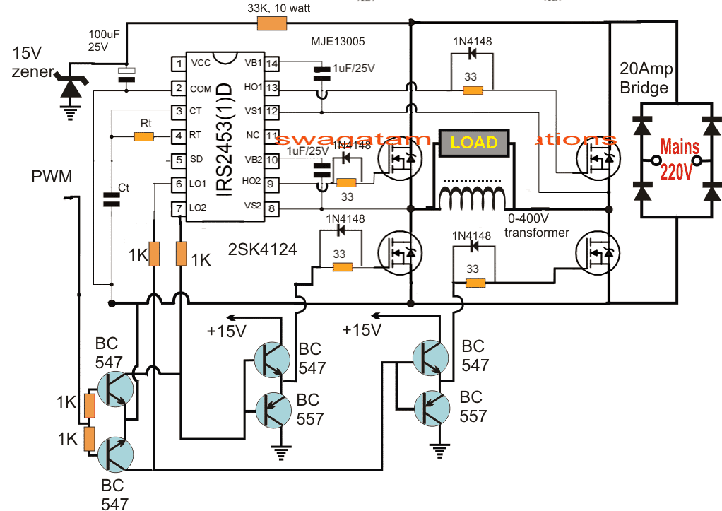
The complete design for the proposed H-bridge mains voltage stabilizer circuit for controlling 100V to 220V can be witnessed in the following figure:
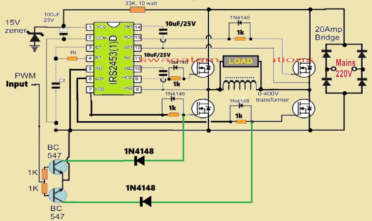
The above design can be much simplified, as given below:
The circuit is functioning is quite similar to one of the earlier discussed posts regarding a solar inverter circuit for a 1.5 ton air conditioner.
However for implementing the intended automatic 100V to 220V stabilization we employ a couple of things here: 1) the 0-400V auto transformer boost coil and the self optimizing PWM circuit.
The above circuit utilizes a full bridge inverter topology using the IC IRS2453 and 4 N-channel mosfets.
The IC is equipped with its own in-built oscillator whose frequency is appropriately set by calculating the indicated Rt, Ct values. This frequency becomes the recommended operating frequency of the inverter which could be 50Hz (for 220V input) or 60Hz (for 120V input) depending on the country utility specs.
The bus voltage is derived by rectifying the input mains voltage and is applied across the H-bridge mosfet network.
The primary load connected between the mosfets is a boost auto-transformer positioned for reacting with the switching mains DC voltage and for generating a proportionately boosted 400V across its terminals through back EMFs.
However with the introduction of a PWM feed for the low side mosfet this 400V from the coil can be controlled proportionately to any desired lower RMS value.
Thus at max PWM width we can expect the voltage to be 400V and at minimum width this could be optimized close to zero.
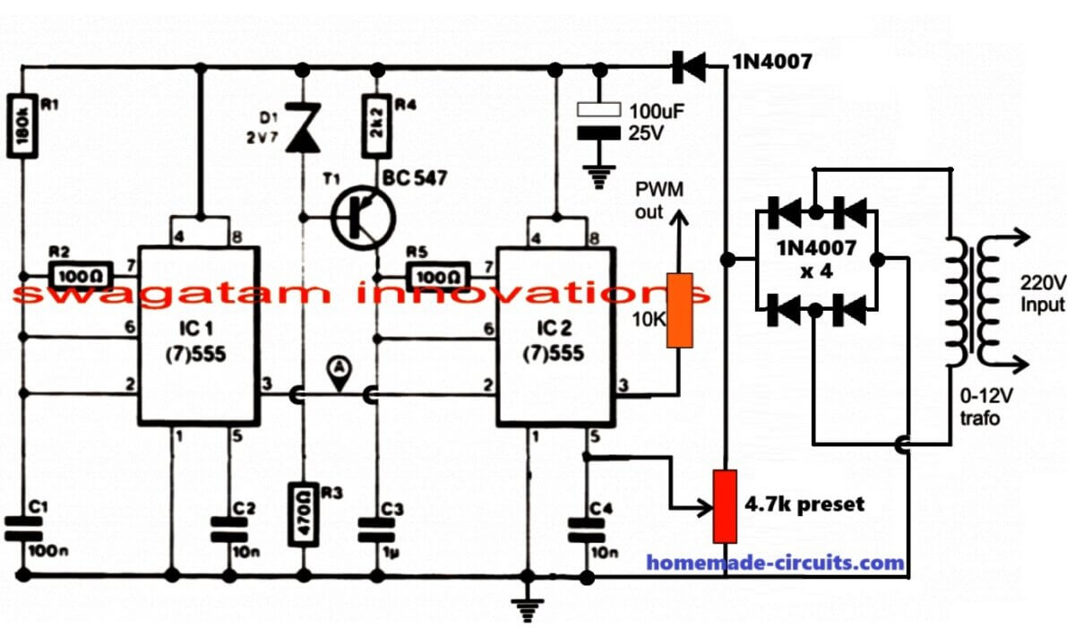
The PWM is configured using a couple of IC 555 for generating a varying PWM in response to the varying mains input, however this response is inverted first before feeding the low side mosfets, which implies that as the mains input drops, the PWMs become wider and vice versa.
To correctly set this response the 1K preset shown attached with pin#5 of the IC2 in the PWM circuit is adjusted such that the voltage across the auto-transformer coil is around 200V when the input is around 100V, at this point the PWM could be at the max width level and from here on the PWMs become narrower as the voltage increases, ensuring an almost constant output at around 220V.
Thus, if the mains input goes higher the PWM tries to pull it down by narrowing the pulses and vice versa.
How to make the Boost Transformer.
A ferrite transformer cannot be used for the above discussed 100V to 220V H-bridge mains voltage stabilizer circuit since the base frequency is adjusted to 50 or 60 Hz, therefore a high grade laminated iron core transformer becomes the ideal choice for the application.
It can be made by winding a single end to end coil of around 400 turns over a laminated EI iron core, using 10 strands of 25 SWG wire...this is an approximate value and is not a calculated data...the user may take the help of a professional auto transformer manufacturer or winder for getting the actual required transformer for a given application need.
In the linked pdf document it is written that its proposed design does not require the AC to DC conversion for the circuit, which looks incorrect and is practically not feasible, because if you are using a ferrite boost transformer inverter then the input AC has to be first converted to DC. This DC is then converted to a high switching frequency for the ferrite transformer whose output is switched back to the specified 50 or 60Hz in order to make it compatible with the appliances.


Questions & Answers
Good day Engr Swagatam. I have tested the inverter section. I used 12v/220v two winding (not center tap) transfo at the “load” point. It works very well with 12v battery and also with rectified 12v from the AC bridge, which means the inverter section will work if the mains rectified voltage and 0-400v transformer is connected.
I later tested the pwm section. I placed LED at pin3 of ic1 and powered the circuit from 12v battery. The LED lights. I turned my digital multimeter (sd10a slim pocket digital multimeter) to dcv range, and selected Hz/duty to read frequency. When I checked, there was no frequency reading at pin3 of ic1. Also I checked the output frequency at pin3 of ic2, it was zero, no frequency reading. I have been using this multimeter to check AC and DC frequency, voltages, etc….
Please, what should I do and what should be the frequency at pin3 of ic1, if that of ic2 should be around 300Hz
Hi Emmanuel,
Please do not connect an LED at pin#3 of the inverter, check it without LED and without any PWM connected. If there would be no frequency at pin#3 of the IRS2453 IC then your inverter wouldn’t have worked.
Thee frequency at pin#3 should be 2 times that of the inverter output frequency.
Actually you must use an oscilloscope to check the waveform, frequency etc, a multimeter may not be enough. You can buy this small oscilloscope and use it for your testings:
https://www.homemade-circuits.com/dso138-best-small-oscilloscope-for-electronic-hobbyists/
Sir, the ICs am referring to were the two 555-timer, not the IRS2453 inverter ic. I have tested the inverter section, and it worked well. Where am having problem is the PWM section that has ic1 and ic2 as 555-timer each. I used frequency meter to check the frequency at pin3 of ic1 and pin3 of ic2, it was zero frequency. What should I do and what should be the frequency reading at pin3 of ic1 and pin3 of ic2 respectively?
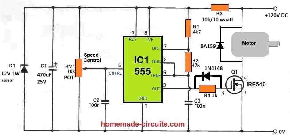
Emmanuel, if you are having difficulty handling the two IC 555 based design, then you can try the following simpler one IC design: Please ignore the MOSFET and the motor configuration, and use pin#3 of the 555 IC to feed the PWM in your inverter circuit….
Thanks for your response. Ignoring the mosfet and motor configuration, if I should supply the one ic circuit with 0-12v transformer bridge just like the two ic 555 based design, won’t the 12v zener diode affect the pwm auto widening or narrowing because it will keep the varying input voltage constant
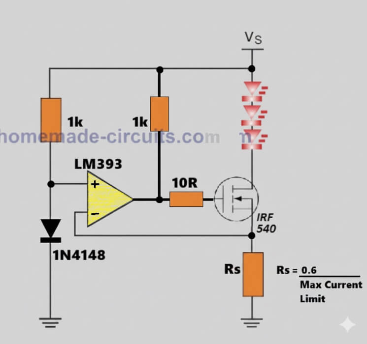
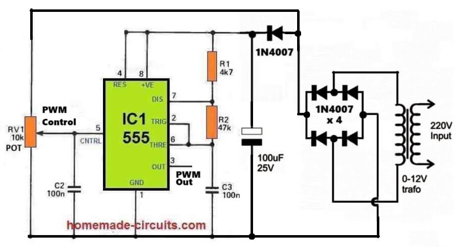
Actually I forgot about the AC synchronization part, here’s the updated diagram which you can now use instead of the two 555 IC circuit shown in the above article:
Good day Engr Swagatam. I connected the circuit on a white bread board. I powered it with a 9v battery to test. I placed my frequency meter and multimeter (at DCV range) to pin3 of the 555 timer. I varied the 10k pot and got 255Hz maximum, 0.88vdc.
Without tampering with the setting, I replaced the 9v battery with 12v battery and got 246Hz, 1.39vdc.
Observation:
I observed that when the supply voltage is low(9v), the frequency increases, voltage at pin3 become lower and when supply voltage increases(12v), frequency decreases and voltage at pin3 become higher. Is this correct? Is the frequency ok?
Good day Emmanuel,
Adjusting the 10k pot should change the PWM, not he frequency. Frequency can be changed by adjusting the R1 and C3 values.
Without an oscilloscope, it is impossible to know what’s going on in the circuit.
https://youtu.be/A3Fmek1VezM
Also please make sure to adjust R1 and C3, so that the PWM frequency is within 300 Hz.
Good day sir. Sorry for asking too much questions. I didn’t change the value of R1 (4.7k) and C3 (104), instead I replaced R2 with 22k. I disconnected only the positive supply from the 10k pot which is connected to pin5 of 555-timer. Other connections were intact. From pin3, I got 288Hz practically from frequency meter. I checked online calculator for 555 timer astable multivibrator. I put in the values and the frequency was 295Hz. Please is my practical result or reading ok or is there any other adjustment to make?
Emmanuel, yes your frequency reading is OK…the practical value can be slightly different to what the online softwares show, which is the ideal value…
Ok. Thank you sir.
Ok. Thank you sir. I will do that.
Good day Engr Swagatam.
I placed the IRS2453 on a white bread board and connected 490k ohms to pin #4 and pin#3, (105+105) capacitors in parallel to get 2uf/50v to pin#3 and pin#2. I also connected the bootstrap capacitors, Grounded pin#5. Without connecting the mosfets, pwm, and 1N4148s, I connnected red LEDs to pin#6, #7, #8, #9, #10, #12, #13, and #14.
OBSERVATION:
LEDs at pin#6 and pin#7 alternates and shines far brighter than pin#8 and pin#9 such that when pin#6 ON, pin#8 and #9 OFF simultaneously, and verse visa.
The same with pin#7 which shines brighter than pin#12 and pin#13 such that when pin#7 is ON, pin#12 and #13 is OFF, and verse visa
Also pin#10 and pin#14 shines brighter just like pin#6 and pin#7.
My question is, since the voltages at pin#8, pin#9, pin#12 and pin#13 are lower, can it drives the high side mosfets?
Good Day Emmanuel,
An H-bridge IC driver cannot be tested with LEDs. You must build the complete inverter design with MOSFETs, and then test the stage with a load, and then you can see whether the circuit is working correctly or not…
Good day Engr Swagatam. I constructed the simplified diagram and the pwm diagram. Instead of 1k ohms and 1N4148 in parallel, I used 33-ohms and 1N4148 in parallel. I used a step down transformer 230v/24v, rectified and power the IRS2453 and another step down transformer 230v/12v, rectified to power the pwm circuit. I connect all grounds together. The supply LEDs indicators for each circuit was ON. For testing, and to avoid any danger, I used another step down 230v/12v, connecting the 12v side to the 20amp bridge and the 230v side to mains through a fuse and switch, and When I switched ON the switch, the mosfets(IRFP260N) smoked and short circuited. I replaced the four mosfets, yet the same burnt occurred.
Please what is the cause?
Hello Emmanuel,
I guess I had suggested you to first test the inverter separately with load, and without a PWM.
So please test the inverter section only without the PWM, and with load.
If it works normally with a load, then next test the PWM section separately using an OSCILLSCOPE, and check whether it is generating the PWMs correctly or not. Set the PWM frequency to not more than 300Hz if the inverter frequency is 50Hz.
If the waveform is good, then next you can integrate the PWM through diodes, as shown in the second figure, in the above article…
Ok sir. I will do that.
Thanks for your response.
In the diagram, pin #5 of IRS2453 was not connected to ground. Should I connect it? I want to do practical construction.
Yes, it must be grounded, it is shown in the second diagram. Please do as per the second diagram.
Good evening Engr Swagatam.
Please I have another question on modification.
What if I connect a step-up transfo of secondary side, 230Vac, primary side of 220Vac, 5amp to 10amp, such that the 230Vac secondary side is connected to the 20amp bridge and the primary to mains and then disconnect the 33k/10w resistor so that the 20amp-bridge will not supply power to the IC (irs2453), but only the H-bridge mosfets high side. Also, there will be another separate small transfo of 0-15v/220v, halfwave rectified to pin 1 of the ic irs2453 to power the ic just like the pwm circuit which has a separate small transfo.
Will it work?
Hi Emmanuel, Yes, your setup will work.
Can this circuit be made with 2 half-bridge IC IR2153?
Thanks in advance.
Can I connect pwm ground 15v zener diode anode pin or ic com pin in second design ?
Yes, all the grounds must be connected in common.
The 15V zener ground, the Low side MOSFET grounds, the PWM ground all must be connected in common…
It is not possible because then how will you synchronize the two ICs to implement the H-bridge operation?
Thanks for your response.
I have few questions
(1)Where i connect the +15V
(2)Can this circuit be made with 2 half-bridge IC IR2153?
You can connect it to the cathode of the 15V zener diode.
I have done some modifications in both the diagrams, please check it.
You mean two +15 volts connect to the cathode of the 15 volt zener diodes, and two bc557 transistors ground connect to the anode of the zener diodes.
In the old diagram, the +15V of the BC547 goes to the cathode of the 15V zener diode, and the BC557 grounds go to the anode or the ground line of the circuit.
Hi, can i used 1uf 400v ceramic capacitor instead 1uf 50v capacitor?
Yes, but it will be so bulky…
Good day Engineer Swagatam.
I have few questions
(1) for the pwm response, using the 1k preset, will it be possible to get around 200vac from autotranformer when the input is around 90vac?
(2) you said the windings of the transformer can be made using 10-strands of 25-standard wire gauge.(a) Is it a must that the coil should be stranded or 10-strands? (b) what is the benefit if it’s up to 10-strands of 25-SWG.
(3) what number of mosfets to be used for 10kva transformer?
Thanks
Good Day Emmanuel,
1) Yes, it is possible.
2) Using a Litz wire enhances the current (Amp) transfer and efficiency of the transformer, that’s why multiple strand wire is recommended.
3) I would recommend building a smaller version of 100 watt first and then slowly upgrading by adding more MOSFETs. You can check the MOSFETs ID and VDS specifications to know how many of them would be required to fulfil 10kva output
Thanks for your response.
If the wattage of the 33k resistor is less than 10watt, what will be it effect to the circuit?
Can I use toroidal transformer core to wind and produce my autotranformer?
The 33k will burn if it is not a high watt resistor above 5 watts wire wound.
You can use toroidal trafo.
Good day Engineer Swagatam,
I couldn’t get 33k,10w resistor. What l got was 22k,10w and 12k, 10w. If I connect both in series to give 34k,10w will it work? Thanks
Good Morning Emmanuel,
Yes, that will do, no problems.
Good day Engineer Swagatam. I couldn’t get 33k,10w resistor in my area. The resistors i got were all white cement ceramic: 5w20kJ, 5w100kJ, 7w1kJ, 7w1kJ, 7w1kJ.
(1) Can 5w20kJ (20k,5watt) work in place of 33k,10watts resistor in the circuit?
Or can I add 7w1kJ, 7w1kJ, 7w1kJ to 5w20kJ to get 23k ohm in place of 33k,10w even if the wattages are different?
Hi Emmanuel,
Yes definitely you can try the 20k 5 watt, it should work, or you can also try adding two 20k in series to make 40k 5 watt and that should also work.
Thanks for the prompt response.
What mosfet would suite a 2kva transformer and are the two circuits above connected to eachother
Yes, both the circuits must be connected to each other…
You can try IRFP2907.
hi swagatam nice job by the way.
Can i use this with a 2kva transformer,if yes what components would i have to change
Thanks Halo,
I would recommend trying with a smaller transformer first, if it works perfectly then you can consider upgrading the transformer to high levels. For a bigger transformer only the MOSFETs will need to be upgraded proportionately.
Hi, can the design make use of a buck boost transformer? I want to use the same design concept for a project but I want the stabiliser to stabilise mains voltage above and below 220 V.
Hi, Sorry, a buck boost transformer might not work in the above design!