In this article I have explained about a peak detector circuit, its working principle and how to implement it in clap operated circuits for illuminating an LED in response to clap sounds.
What is Peak Detector
A peak detector is a circuit which holds maximum amplitude value of a signal. If a signal varies rapidly and we are unable to measure it, then we go for peak detector. This circuit holds the maximum amplitude value for short period of time so that we can measure it.
There are many ways to do this and often used in many fields in electronics where rapid measurement is not viable.
For instance, taking heat gun thermometer as example, where the temperature of an object may vary rapidly at some situations, the peak value of temperature and current value of temperature is displayed simultaneously so that user can get an idea about the object.
Similarly, there are many situations in electronics, where we may need to measure peak signals.
How it works?
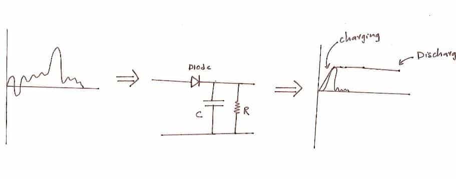
Here, we are going to see simple peak detector circuit that consists of one diode, one capacitor and one resistor.
The diode permits the current in one direction, which is to charge the capacitor.
When the input drops the capacitor holds the value for a short period which gives some time to measure the peak. Here the short period could be ranging from a few milliseconds to a few seconds.
The values need to be refreshed time to time so that new values can be stored. To do this we need to discharge the capacitor. A bleed resistor is connected parallel to capacitor which discharges.
The capacitor discharge time can be calculated by the following formula:
T = 5 x C x R
Where, T is time in seconds
C is capacitance in Farad
R is resistance in Ohm
Clap Sensor circuit:
Here, we will implement the peak detector in a clap sensor circuit. This circuit responds to loud busts of sound such as clap.
There are three stages in this circuit, the microphone amplifier, peak detector and op-amp circuit that detects peak.
The sound gets converted to electrical signal by the microphone, gets amplified by op-amp. The amplified signal enters the peak detector circuit and charges the capacitor. The peak value stored in the capacitor becomes the peak input minus 0.7V for silicon diodes, since there will be always voltage drop across diode.
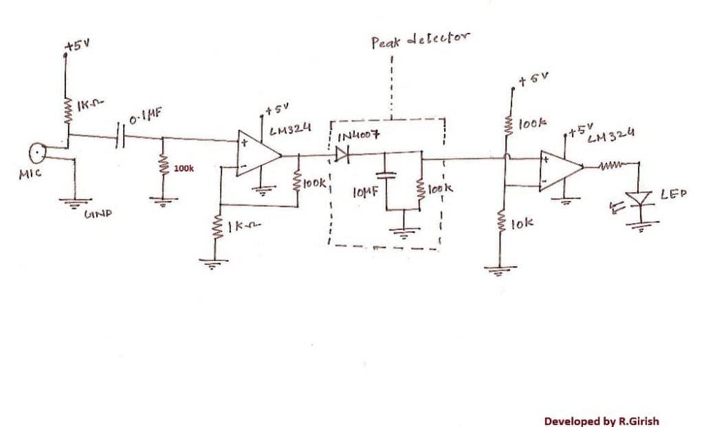
The value stored in the capacitor gets recognized by op-amp comparator circuit.
As soon as the peak value goes above reference voltage the LED turns ON.
As soon as the capacitor is discharged below reference voltage the LED turns OFF.
So, what was the role of peak detector in this circuit? Well, it holds the clap signal for few 100 milliseconds which helped the LED to stay illuminated for a few 100 milliseconds. If you wish LED to light longer, it can be done by incrementing capacitance and resistor values.
How to Measure the Peak Voltage in a Peak Detector Circuit
If you are wondering how to measure the peak level in a peak level circuit, you can take the help of the following circuit diagram:
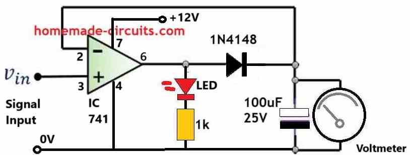
The above diagram shows a simplest peak voltage level detector circuit with a voltmeter which can be used to measure the peak levels of an input signal.
How it Works
Let's imagine, initially the charge stored inside the 100uF is zero, which means there's zero voltage across the capacitor and pin#2 of the op amp.
In this situation if an input signal is applied, a peak voltage of even a 0.2V will be enough to cause the non-inverting pin#3 of the op amp to become higher than its inverting pin#2.
Due to this the output pin#6 will instantly go high, however it cannot reach the Vcc supply level of 12V. Because the moment the output exceeds the 0.2V mark it is fed back to pin#2.
This exceeding potential level at pin#2 which tends to get higher than the instantaneous 0.2V signal input at pin#3, causes the op amp output to revert to 0V. Thus the peak level is locked at 0.2V across the capacitor.
The capacitor being charged at 0.2V holds this value for a certain amount of time, which can read on the meter, connected across the capacitor.
Now, in the meantime if a new peak voltage arrives at pin#3 higher than 0.2V through the input signal, it causes the output to yet again turn high. Let's say the new peak is 1V.
Due to the fact this new 1V at pin#3 is higher than the existing 0.2V at pin#2, causes the output pin#6 to become high.
As pin#6 gets high, its voltage level yet again tries to move towards 12V (Vcc), but the moment it exceeds 1V, it makes pin#2 higher than pin#3, which quickly reverts the output to zero volts.
The new peak of 1V is now stored inside the capacitor and displayed on the meter.


Questions & Answers
hi sir
can i uesd this schematic for 100hz pulse Voltage in a Peak Detector thank you
Hi jhjh, yes you can use the above circuits with 100Hz frequency.
Hi sir, can I use a Fluctuating voltage signal instead of the mic, so as to detect the time period of voltage rising, peak value of voltage and indication of peak value using an LED. if so can you suggest the necessary circuit conditions and connections i need to take
Hi Joe,
You can use a fluctuating voltage as the input.
In that case you can remove the MIC and the series 1k resistor, and apply the input voltage directly to the 0.1uF.
Also sir, how to calculate the time it took to reach the peak, because fluctuating signal is such that its decreasing first from 5v, and after a particular point it rises to a peak within 5v, and goes to zero. So the time it took to reach the peak from the rising point needs to be calculated….is there any way for that sir
Hi Joe,
Measuring the peak time can be very difficult, I have no idea how to solve it right now.
Well explained
Good Day,
Can this be used on an amplifier circuit? I need a simple peak detector circuit or a vu meter with about 4 led’s
Good day, yes it can be used according to me….