In this post I have explained how to correctly calculate inverter parameters with associated stages such as battery and transformer, by calculating the matching the parameters correctly.
Introduction
Making an inverter all by yourself can be definitely lot of fun. However if the results are not satisfactory can completely spoil the whole purpose of the project.
Installing and configuring the various inverter parameter like the battery and the transformer to with the actual assembled circuit needs special care and attention for deriving optimal results from the assembly.
In this article I have explained how to calculate and match a battery and transformer wit the relevant circuit and also enlightens regarding the possible faults that might be encountered and the respective troubleshooting procedures.
The article enlightens the many newcomers with some of the important clues, which might be helpful while configuring an inverter circuit with the battery and the transformer, so that efficient and optimal results can be achieved.
Calculating Transformer and Battery Specs
While making an inverter, two calculations must be broadly taken into account, viz. the transformer and the battery ratings.
1) The transformer must be rated higher than the maximum load that is expected to be used with the inverter. For example if the intended load is 200 watts, then the transformer must be rated at minimum 300 watts. This will ensure a smooth running of the inverter and less heat generating from the transformer.
The voltage rating of the transformer must be slightly lower than the battery voltage for square wave inverters.
However, for concepts involving PWM or SPWM, it should be equal to the average voltage (x 2) applied at the gates of the MOSFETs.
This can be measured by measuring the average DC voltage applied at the gate of the MOSFETs from the oscillator stage and then multiplying it by 2. So, suppose your battery voltage is 12 V, but because of PWM your average switching voltage from the oscillator shows 3.5 V DC, that implies your transformer must be rated at 3.5 x 2 = 7V. Meaning its primary should be rated at 7-0-7 V and not 12-0-12 V.
2) And the battery Ah must be rated 10 times more than the maximum current rating of the load. For example if the battery is 12V rated and the load 200 watts, then dividing 200 with 12 gives us 16 amps. Therefore the battery Ah must be 10 times of this amp rating, that is 160 Ah. This will ensure your battery runs with a healthy 0.1C discharge rate and provides a back up of around 8 hours.
Calculating MOSFET Rating
Calculating MOSFET for an inverter is actually quite simple. One has to take into account the fact that MOSFETs are nothing but electronic switches, and must be rated just like we rate our mechanical switches. Meaning the MOSFET's voltage and current ratings must be adequately selected so that even at the maximum specified load, the MOSFET working is well within its breakdown level.
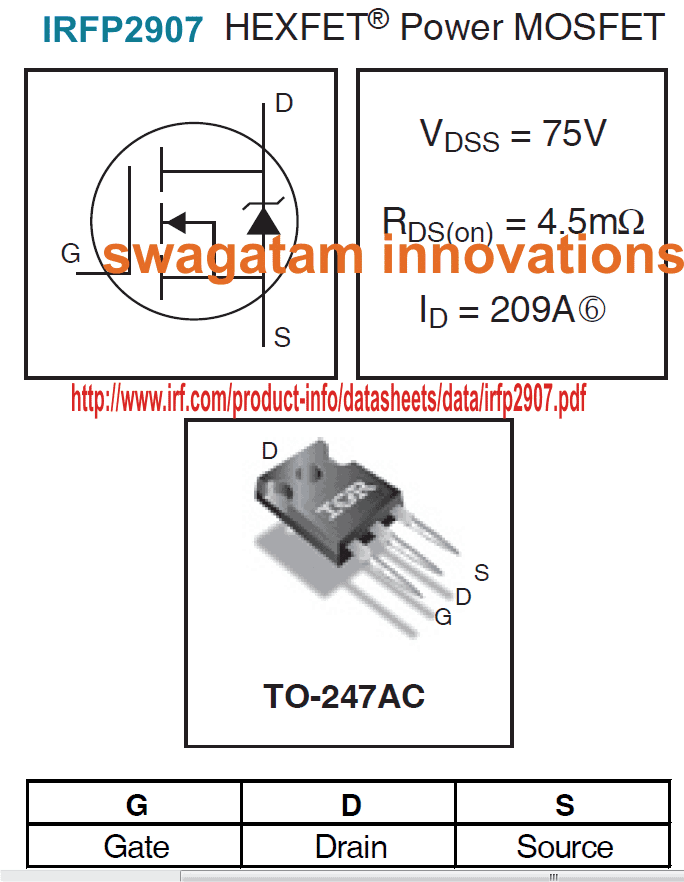
To ensure the above condition, you can refer to the datasheet of the mosfet and check the Drain-Source Voltage and the Continuous Drain Current parameters of the device, such that both these values are well above the load's maximum consumption values, or are selected with appreciable margins.
Suppose if the load is rated at 200 watts, then dividing this with the battery voltage 12V we get 16 amps. Therefore the MOSFET could be selected with voltage ratings anywhere between 24V to 36V as its Drain-Source Voltage (Vdss), and 24 amp to 30 amp as its Continuous Drain Current (Id).
Take the example of the MOSFET in the image above, here the maximum tolerable voltage Vdss of the specified MOSFET is 75V, and maximum tolerable current Id is 209 amps, when operated with proper heatsink. It means this MOSFET can be safely used for all applications where the load wattage is not more than 14000 watts.
Although in real life the load handling capacity may be even lower than this.
As a rule of thumb, make sure the Vdds x Id value is at least 30% higher than the max load wattage, and the MOSFETs are adequately heatsinked.
This takes care of the MOSFETs, and ensures a perfect working of the devices even at full load conditions, but do not forget to mount them on appropriately dimensioned heatsinks.
After procuring all the necessary components as explained above, it would be important to get them checked for compatibility with one another.
Only the battery, which is one the most crucial member, hopefully will not require any prior checking, because the printed rating and the charged voltage conditions should be sufficient to prove its reliability. It is assumed here that the condition of the battery is good and it’s relatively new and “healthy.”
Calculating MOSFET Switching Parameters
The gate resistor affects the charging and discharging of the MOSFET's gate capacitance which determines the switching speed.
Turn-on/Turn-off Time:
ton/off = Rg * Cg
Where:
Rg = Rg(ext) + Rg(int), the total gate resistance (external + internal).
Cg = Qg / Vgs, the equivalent gate capacitance.
Vgs is the gate drive voltage.
The peak current required to charge/discharge the gate can be calculated using the formula:
Ig = Vgs / Rg
The power dissipated in the gate resistor during switching can be calculated using the formula:
PRg = fs * Qg * Vgs
Where:
fs is the switching frequency.
Qg is the total gate charge.
The rate of voltage change during the switching period is:
dv/dt = Ig / Coss
Where Coss is the MOSFET's output capacitance.
Power losses is simply equal to the sum of conduction and switching losses.
Formula for Calculating the Conduction Losses:
Pcond = ID2 * RDS(on) * D
Where:
ID is the drain current.
RDS(on) is the on-resistance.
D is the duty cycle.
Formula for Calculating the Switching Losses:
Psw = 0.5 * VDS * ID * (ton + toff) * fs
Where ton and toff are determined by Rg.
To select Rg:
Use the switching time formula:
ton/off = Rg * Qg / Vgs
Solving for the Rg to achieve the desired switching time.
Ensuring the gate drive current:
Rg <= Vgs / Ig(max)
Check that Ig(max) is within the capability of the driver.
Adjust for dv/dt and EMI:
Increase Rg to reduce EMI and ringing but avoid overly slow switching.
Use a fast recovery or Schottky diode with a reverse voltage rating at least equal to Vgs.
The diode allows faster turn-off while controlling the turn-on speed with Rg.
Example Calculation:
MOSFET Parameters:
Qg = 50 nC
Vgs = 10 V
Gate driver current capability = 2 A
Calculations:
Selecting the ton/off:
The Desired ton/off = 100 ns
Rg = ton / Cg = 100 ns / (50 nC / 10 V) = 20 ohms
Check Ig:
Ig = Vgs / Rg = 10 / 20 = 0.5 A (looks well within driver capacity).
Confirming the switching losses:
For fs = 100 kHz, VDS = 50 V, ID = 10 A:
Psw = 0.5 * 50 * 10 * 200 ns * 100 kHz = 0.5 W
Checking the transformer
The transformer, which is the most important component of the inverter, surely needs a thorough technical assessment. It may be done as follows:
The rating of the transformer can be best checked in the reverse order, i.e. by connecting its higher voltage winding to the AC mains input and checking the opposite winding for the specified outputs. If the current ratings of the lower voltage section are within the maximum limits of a regular multi-tester (DMM), then it may be checked by switching ON the above AC and connecting the meter (set at, say AC 20 Amp) across the relevant winding.
Hold the meter prods connected across the winding terminals for a couple of seconds to get the readings directly on the meter. If the reading matches with the specified transformer current, or at least is close to it, means your transformer is OK.
Lower readings would mean a bad or a wrongly rated transformer winding. The assembled circuit broadly needs to be checked for proper oscillation outputs across the bases of the power transistors or the MOSFETs.
This may be done by connecting the circuit to the battery, but without including the transformer initially. The checking should be done using some good frequency meter or if possible using an oscilloscope. If the above gadgets are not there with you, a crude testing can be performed using a pair of ordinary headphones.
Connect the headphone jack to the bases of the relevant power transistors; you should get a strong humming sound in the headphones, confirming a sound functioning of the oscillator stages.
The above confirmations should be enough to prompt you to configure all the sections together. Connect the transformer to the relevant transistor or the power devices terminals; make sure the power devices are correctly integrated with the oscillator stage.
Installing the Final Inverter Set up
Finally the battery may be connected to the power inputs of the above configuration, again do not forget to include an appropriately rated FUSE in series with the battery positive. The output of the transformer now may be attached with the specified maximum load and the power may be switched ON.
If everything’s is wired up correctly, the load should start operating at its full fledged power, if not, then something’s wrong with the circuit stage. Since the oscillator section was appropriately checked before the final installations, surely the fault may lie with the power device stage.
If the fault is associated with low power outputs, the base resistors may be tweaked for possible faults, or may be reduced by adding parallel resistors to their existing base resistors.
The results may be checked as discussed above, if the results are positive and if you find improvements in the power outputs, the resistors may be further modified as desired, until the expected power output is delivered.
However, this may lead to further heating of the devices and due care must be observed to keep them under check by either including cooling fans or increasing the heatsink dimensions.
However if the fault is accompanied with blowing of the fuse would mean a definite short circuit somewhere in the power stage.
Troubleshooting the Inverter Connections
The problem may also indicate a wrongly connected power device, a blown-of power device due to a possible shorting between the power device’s output terminals or the any of the terminals that needs to be perfectly kept aloof of each other.
Having explained a few of the above possibilities while configuring an inverter optimally, a thorough knowledge regarding electronic becomes an absolute necessity from the part of the individual who may be involved with the construction, without which the proceeding with the project may somehow get jeopardized.


Questions & Answers
Hello Sir,
If I use 12v battery,
Max load I need is 25w,
Transformer output = 62.5w,
Transformer current = 62.5/12 = 5.2083A => Used 5A
Battery current = (5.2083/4)+5 = 1.302075+5 = 6.3A => Used 10A,
Now my question is,
What is the maximum backup time in hour(if maximum load connected is 25w)?
Chandrajith
Helo Chandrajith,
25 watt would consume 25/12 = 2amps, so dividing 10AH with 2 = 5hrs
Therefore ideally the back up time should be 5hrs, however practically it could be less than 4 hours.
Good day Swagatam,
Do I need to pair this article with the other article entitled "How to calculate and match solar panel,etc…" ?
Good day Eshkariel,
the two articles deal with different parameters of the same subject, so they cannot be exactly compared.
Hello Sir,
If i use a 12-0-12v 20 amp transformer, will it give 24v X 20amp = 480va from the transformer?
hello santanu, yes it will give 24V/20amp
Sir,
Do you mean 24-0-24v centre tap or 12-0-12v centre tap transformer?
You mentioned 12-0-12V, so it is for 12-0-12V/20amps… that's equal to 0-24V/20amps
Sorry Sir,
I misread your last answer, n thats why i had asked you the foolish question. One more thing can i upload an pwm inverter circuit diagram whose pwm part has been made according to one of your post but i have some douts in its output waveform & i dont have a oscilloscope to check the waveform. Could you kindly help me out. I need it badly for my home.
Regards,
Santanu
You can upload it in any image hosting site and provide the link to me, I'll check the issues you are having.
Sir ,
I have uploaded the image. Below is the link of the same.
s13.postimg.org/zczkg85w7/20140915_160747_1.jpg
Kindly provide me the necessary correction because i have douts in the connection of the PWM diodes to the mosfet.
Regards,
Santanu
Santanu, a 555 IC is not recommended for driving push pull mosfet stage, because it is not equipped with a dead time feature, you must use an SG3525 or TL 494 type of IC for driving the mosfet stage.
THe PWM will need to be connected at the bases of additional driver BJTs, as shown in the LAST diagram of this article:
https://www.homemade-circuits.com/2013/08/homemade-100va-to-1000va-grid-tie.html
https://www.homemade-circuits.com/2013/04/how-to-modify-square-wave-inverter-into.html?m=1
The link you provided doesnt exist.
can i use the circuit you provided in the above link and modify it into a 500 watt inverter by adding 2 more mosfets in each channel.
Regards,
Santanu
You might have not copied the link correctly, it definitely exists.
Yes you can use the above link PWM stage
Sir,
The link you provided is not working.
The square wave portion of the cicuit (having ne555 and mosfet)which i provided to you is working properly. I need to increase its wattage to 500 watt and thats why i added 2 more mosfets in each side. Initially i have built the circuit using single mosfet in each side.
My query is that will increasing the number of mosfet will increase the wattage and if so how should i connect the mosfets and how do i connect the pwm diodes to it to get the output.
If i am wrong please correct me and advice me what to do.
Regards,
Santanu
Check it again, it surely works.
high frequency PWM can be added to the mosfets only after adding a BJT buffer stage before the mosfets as shown in the previous link
https://www.homemade-circuits.com/2013/08/homemade-100va-to-1000va-grid-tie.html
otherwise your mosfets can become hot….
you can try the design that you have made, if it works for you, it'll be great
first make a smaller version, if it works smoothly only then you may think of upgrading it to higher watts.
Sir,
I have copied the link numerous times but it says the page you are looking in the blog does not exist.
…in my computer it opens instantly, I don't know the reason why it's not opening in your PC
Sir,
Can i use ne555 to generate sqaure wave and then fed the output from pin no#3 to pin no#2 of another 555 ic wired in monostable mode to generate pwm pulse, and then fed the pwm output from pin no#3 of 555 ic via bjt buffer stage to power mosfet and then to a ct 12-0-12 transformer to achieve 230v ac modified sine wave.
I can't suggest a PWM for an IC 555 inverter, you have to either use a 4017/555 based, or SG3525, or a 4047 IC based inveter circuit for making a PWM compatible unit. The BJT stage will need to be implemented as given below:
1.bp.blogspot.com/-NgqlieM8TX8/U7zL0tGH6qI/AAAAAAAAHgE/WCKLVG9pVVs/s1600/mosfet+transistor+driver+circuit.png
I hope this link opens for you.
I went through the bjt buffer stage provieed in the link provided by you. I want to know that can i use the bjt buffer circuit to an bjt amv circuit including a bjt amv chopper pwm circuit. Link given below.
https://www.homemade-circuits.com/2013/04/how-to-modify-square-wave-inverter-into.html?m=1
yes you can use it with this circuit
Sir,
If i use a bc547 astable multivibrator to generate square wave and apply high frequency pwm to it as shown in one of your post (link given below).
https://www.homemade-circuits.com/2013/04/how-to-modify-square-wave-inverter-into.html?m=1
I know that sg3525 is a pwm generating ic and is much more efficient in matching the rms value that a bjt orient pwm inverter, am i right Sir, thanks for your valuable advice on 555 ic, i made the circuit and applied pwm to the 555 square wave inverter, i found it very difficult to match the rms value exact to 230 but when i made the bjt oriented AMV circuit and applied the AMV chopper circuit which delivers high frequency pwm it was much easier to adjust the rms to 230 and the mosfet are not getting too much hot. What you suggest me to do should i go for sg3525 or for the bjt amv one.
regards,
Santanu
Satanu, it's not about efficiency, it's about having a totem pole output, meaning two outputs with push pull actions. a SG3525, or a 4047 or a 4017 ICs will have two separate outputs for the BJTs/mosfets, which makes it easier to add the PWMs at the respective channels.
The transistor AMV circuit is also good since it too has two separate channels for the PWM injection, you can go ahead with it.
Sir,
Thank you for your advice.
Sir now a days i see the emergency lights having cfl in place of led, are those cfl 6v cfl? If yes then can you design a circuit to drive the cfl with a 6v battery also having a battery charger in it?
Regarfs, santanu
Santanu, actually it should be the opposite, today CFLs are getting replaced with LEDs, can you show me the image it would help to understand the specs.
Sir,
I would try to upload an image.
I have built the bjt amv circuit and its running fine. I am using a 12-0-12v 6amp transformer and 12v 7.2ah battery.when i run a normal cfl or bulb it runs smoothly but when i try to run a table fan possibly of 100watt the fan run slowly and makes an awkward noise. I think increasing the battery amp would solve the problem. I am thinking of adding 1 more 12v7.2ah battery in parallel. Am i wright sir????
A 100 watt load could be too big for a 7AH battery, so yes the battery AH will need to be increased appropriately for the fan and the circuit to work optimally.
1.bp.blogspot.com/-NgqlieM8TX8/U7zL0tGH6qI/AAAAAAAAHgE/WCKLVG9pVVs/s1600/mosfet+transistor+driver+circuit.png
In the above given link there are 2 nos. of 1n4007 diodes for pwm injection. I need to know that if i use 1n4148 diodes in place of the 1n4007 diodes as shown in one of your post, does it make any difference? I think no. Please rectify me if i am wrong. Link given in next post.
Regards,
Santanu
1N4148 can be used instead of 1N4007, that would make no difference in the performance of the system.
https://www.homemade-circuits.com/2013/04/how-to-modify-square-wave-inverter-into.html?m=1
The above link is the link mentioned in my previous post. Please reply soon.
Regards,
Santanu
yes, 1N4148 can be used instead of 1N4007, that would make no difference in the performance of the system.
please sir how can i know the number of mosfet for a 2000w inverter
multiply the V and I of the mosfet and divide 2000 with this result
Hello sir Swagatam,
Thanks a lot for the article. The article didn’t cover how to accurately calculate the number of MOSFETs that will match a specific transformer and battery ratings in an inverter system. Kindly shed more light on that.
Anticipating your usual prompt response. Thanks.
Hello Godson,
mosfets are nothing but electronic switches, therefore they simply need to be rated as per the transformer consumption. if the transformer primary is rated to consume say 20 amps max, the mosfets must be rated at 25 amps, that’s a little higher than the maximum consumption value.
Hello sir Swagatam,
Thanks for the prompt reply. What I meant was that supposing I want to build a 2KVA inveter that will run on 24V battery, how do I know how many MOSFETs to use?
Hi Godson,
divide 2000 with 24, this will give you the mosfet current, make sure to select 10 amps above this value for the mosfet on each channel.
voltage rating will be 10V higher than 24V that is 34V .
higher values will work, but not the lower values.
Thanks for the reply sir.
Using the example of the 2KVA, 24V above, here is what I understood from your explanation:
2000/24 = 83.3A
83.3 + 10 = 93.3A
Using IRFP150N MOSFET which has a continuous drain current of 42A and voltage rating of 100V,
Number of MOSFETs on each channel = 93.3/42 = 2
Is this calculation correct sir?
Where does the voltage rating that you mentioned above come in to this calculation?
According to me that’s correct!!
the voltage rating has to be simply 10V higher than the battery voltage…
make sure to add good heatsinks, which is always compulsory for inverter devices.
Good day sir,I have been following your post all this while and i find them motivating especially to people like me.
pls sir I need your help cocerning protecting my inverter .
and i dont really know some causes ,how can i go about it ;
some of them are ; mosfet got burnt ,unable to control the charging ,making noise that is fan make some umming noise when inverter is in use ,how do i protect my oscillator,…
Hi Ag, I have covered all these topics in this website, it will be difficult for me to explain all these separately through comments, you can search the topics through the search box, you might find some help
OK, thanks for your response. Am working on a 3kva inverter, how many mosfets do I use in total. Thanks
Sir Swagatam I have followed your link for a number of weeks now and I find it interesting. sir I want you help me on this
let me use you 3kva circuit with 3 fet transistors per channel sir
if I want to use 10 on each side , what will be the current consume by each transistor (irf 3205) under 24v battery and also what will be the maximum power delivered by the inverter
thank you sir
Osei, Please check the ID and VDS ratings of the mosfet through its datasheet, and multiply them to get the maximum tolerable wattage of the device. Make sure your expected power output is less than this, and the MOSFETs are mounted on heatsink.
Output power is decided by the transformer and the battery, the MOSFETs only work like switches and must be rated appropriately to handle and execute the specified amount of power.
thanks for your quick response sir
sir Swagatam thanks allot
please I want you to help on this if they ok.Sir supposing I’m using a transformer from 5kva stabilizer for 4kva inverter under 24v battery.
total current will be 4000/25 = 167A sir
if 10 fet (3205) per side then current handle by each fet will be 167/20 = 8.35A because they connected parallels sir. also power handle by each fet will be 24v *8.36a = 200w is this ok
Sir can I use this transformer for 5kva inverter sir? thanks
Osei, each channel will be subjected to 4000watts, therefore each FET will share 167/10 = 16.7 amps according to me, and power will be 24 x 16.7 = 400 watts
Thank you sir or should I call you teacher