In this article I have explained how to calculate and the find the value of the zener diode resistor using simple formulas.
What is a Zener Diode
Zener diodes are semiconductor devices which are used for regulating an input DC voltage to any desired output voltage. The regulated output voltage value directly depends on the value of the zener diode.
However, all zener diodes being vulnerable to high currents, strictly require a current limiting resistor to control the maximum current through the zener diode.
This resistor also decides how much maximum current the output load can acquire. Thus, the zener diode resistor must be selected in such a way that it ensures proper safety to the zener diode from excessive current, and also allows sufficient current for the output load, so that it can operate optimally.
As shown in the figure below, R1 and the zener diode D1 reduces the input voltage VIN to the desired output voltage VOUT.
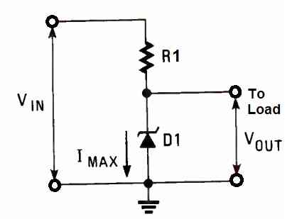
The operating voltage of the zener diode is fixed by the manufacturer of the device. While selecting a zener diode we match its operating voltage with the required VOUT voltage.
Power Dissipation
Another important parameter of a zener diode is its power dissipation, which is given by the formula:
P = VOUT x IMAX
Just as VOUT is decided by the load, Imax is also determined by the load. Imax is also determined by the resistance and wattage of the resistor R1.
To be precise, VOUT and Imax are both decided by the minimum and the maximum values of the load current.
This is because, first the current has to flow through the resistor R1 before passing through the zener diode and the load. Therefore the R1 current can be expressed from the following formula:
IR = IZ + IL (Equation#1)
- Here, IR = current through resistor R1
- IZ = current through zener diode D1
- IL = current through the output load
Calculating Current through Zener Diode Resistor
If we consider the input voltage VIN and the output voltage VOUT to be relatively steady and constant, the current flowing through resistor R1 will be proportional to the voltage across it (by Ohms law). This can be expressed with the following equation:
IR = ( VIN - VOUT) / R (Equation#2)
Combining (Equation#1) and (Equation#2), we get:
(VIN - VOUT) / R = IZ + IL (Equation#3)
As assumed earlier, the (VIN - VOUT) is much constant. Therefore when the load current is minimum (let's call it ILmin), the current through the zener diode will be maximum (let's call it ILmax). Substituting these factors in the above equation#3, we get:
(VIN - VOUT) / R = ILmax + ILmin (Equation#4)
If suppose we have a load that demands only maximum current, then the current through the diode will be always negligible. Therefore the above equation can be reduced to the following equation:
(VIN - VOUT) / R = ILmax (Equation#5)
The above equation is simply telling us that the resistor R1 should be selected not only to protect the diode but also to supply adequate current for the load.
Now, we can rearrange the above equation as follows:
R = (VIN - VOUT) / ILmax (Equation#6)
Once the above equation is solved and we get the value of R, we can easily calculate the power of the resistor using the following equation:
P = (ILmax)2 x R (Equation#7)
The above calculations thoroughly explains how to calculate a zener diode resistor!
Maximum Reverse Current
It is also possible for us to determine the maximum reverse current of the zener diode. This can be done by rearranging the Equation#4, and substituting it in Equation#5:
Imax = ILmax - ILmin (Equation#8)
The above equation simply illustrates that the zener diode adjusts its current dissipation and compensates for the maximum and minimum load currents.
It also illustrates that the zener diode pulls current through the resistor to generate a voltage drop across the resistor, which proportionately reduces the voltage for the load.
Questions & Answers
I sent a question in your Email
I could not find any email in my inbox…
sent you question in homemadecircuits@gmail.com
Hi, I think you can simply try the following software for the calculations, let me know if you have any further questions:
https://www.homemade-circuits.com/zener-diode-calculator/
Hi,
I designed an overvoltage protection circuit. My input voltage is 90V, and I need overvoltage protection at 90V. However, I used a 90V zener diode in my circuit. I have a problem calculating the current limiting resistor for the zener diode because the formula for calculating the resistor value is [𝑉supply−𝑉zener]/ zenercurrent(Iz).
In this case, if I calculate my values[ Vsupply is 90V and Vzener is 90V], it will become zero. What should I do?
Note: I will send the reference design if you need it.
Regards,
Nitheesh
Hi, The zener diode will conduct current only when the supply voltage is slightly higher than the firing voltage of the zener. If the supply voltage does not exceed the firing voltage of the zener diode there will be no current passing through the zener, and therefore no limiting resistance would be required.
That is exactly why the formula is giving a zero resistor value.
Make sure the supply voltage is at least 1V higher than the zener voltage.
Hi,
Thanks for your response.
So, if I set the supply voltage to 90V and the Zener voltage to between 80V and 89V, will it work correctly?
Regards,
Nitheesh
Yes it will work correctly, assuming your 90V supply is always constant and will never exceed this value.
I want to switch on the step down transformer, which drives a load of 5A/15V, when the solar voltage is higher than 12V and switch it off again when the voltage is below 12V.
Thanks a lot for your advice. I was a little confused as in your circuits, the diode was from the resistor to negative and this was not working for me. So I put it in series with the resistor and it seemed to work.
You are welcome.
When the zener is connected across gate and negative, it keeps the gate voltage constant, when connected in series, the zener allows the gate trigger to happen only after a specific voltage threshold.
So, both the positions have different outcomes.
Yes, it should work. The MOSFET configuration looks correct to me.
By the way, that is not a transformer, that is a buck converter. The term “transformer ” was creating the confusion.
Hello.
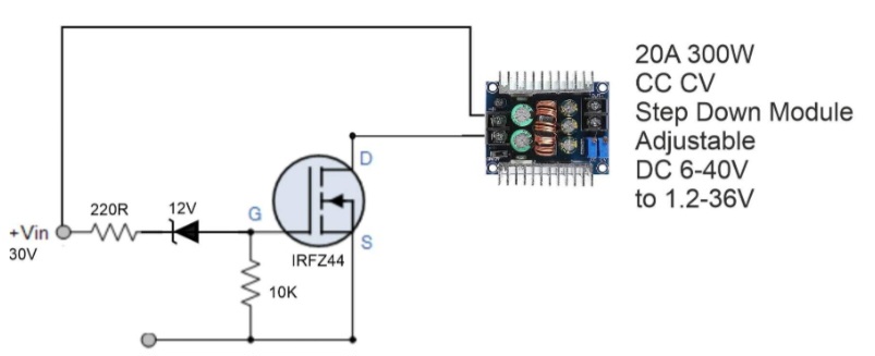
I have a variable input from a solar panel 0-30V. After a 220ohm resistor my zener diode 12V – 1N4742A is in series with the anode facing the resistor. The cathode is connected through a 10K resistor to negative and the source of a IRFZ44. The gate is connected to the diodes cathode and the drain to the negative Vin of the step down module and the Vin + to the positives 30V.
I want the step down transformer to produce a signal of 14V and is cut from the panel below 12V. Will my circuit will work?
Thanks!
VESPUCCI
Hi, sorry I cannot interpret the circuit in my mind, can you please draw the schematic and provide the link, I will try to figure it out.
this is my step down transformer:
https://upload.disroot.org/r/WdPh5MYy#bCOzKWAUJdtMfBb6+YcPHG+uo//AU8zC2gDEcEIBnvE=
Is it a buck converter? In your previous diagram you should a transformer. What is the purpose of the transformer.
Thanks for the schematic,
But a transformer won’t work with a DC supply, it has to be an AC or a pulsed DC.