• Skip to main content
  • Skip to primary sidebar

Homemade Circuit Projects

Need circuit help? Post them in the comments! I've answered over 50,000!

Blog | Categories | About | Contact | Calculators-online
You are here: Home / Electronics Theory / Astable Multivibrator Circuit Using NAND Gates
warning message: electricity is dangerous, proceed with caution
Astable Multivibrator Circuit Diagram Using IC 4093 NAND Gate2C Image

Astable Multivibrator Circuit Using NAND Gates

Last Updated on November 1, 2019 by Swagatam 4 Comments

An astable multivibrator is referred to an electronic configuration which is able to generate continuous alternate high and low pulses from a couple of outputs, operating in tandem.

Table of Contents
  • Why IC 4093
  • Using NAND Gates

Why IC 4093

You might have well come across such astable circuits using a couple of transistors, a couple of capacitors and a few resistors.However more simpler and effective astable multivibrator circuit can be built usng a single IC 4093.

The IC 4093 basically consists of four individual NAND gates in one package, these are schmitt trigger types, which means the gates provide some sort of hysteresis at their outputs in response to the input signals.

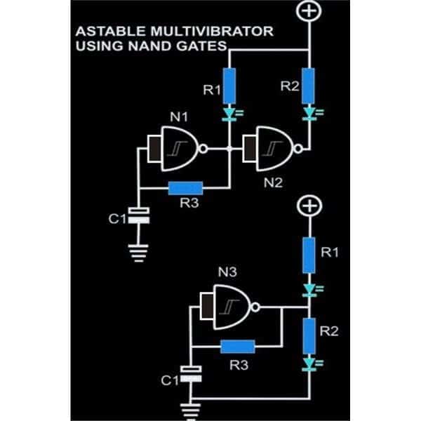
The circuit diagram shows how simply just a couple of gates may be configured into an effective astable mutivibrator circuit.

Using NAND Gates

In the figure, gate N1 and the associated passive parts R3 and C1 form the basic oscillator stage. The output of N1 generates alternate square wave pulses at its output having fixed mark and space ratio.

The frequency of these pulses can be varied as per the users choice by simply changing the value of either R3 or C1.
Preferably, R3 may be replaced with a 100K pot for facilitating quick alteration of the pulse rates.

The output frequency may be set by using the formula f = 1/T = 1/2.2RC, where R is R3 and C is C1 in the shown diagram.

The pulses generated at the output of N1 is fed to the input of the next NAND gate, which is wired up as an inverter by shorting its input pins. Note that basically the inputs of all the gates are short circuited, thus they all behave as inverters here.

As the name refers to, in an inverter mode the gate N2 just inverts the response from N1 at its output.

It means that, when the output from N1 is high, the output of N2 become low and vice versa.

The outputs of these gates are able to support LEDs directly at their outputs, so we connect a few of the LEDs at their outputs which dance or blink in response to the astable pulses.

The bottom figure shows how a single gate may also be wired for obtaining results exactly similar to the upper design.

Astable Multivibrator (AMV) Circuit Using NAND Gates or IC 4093

R1, R2 = 1K,
R3 = 100K pot
C1 = 10uF/25V
IC = 4093

You'll also like:

  • 1.  Unijunction Transistor (UJT) – Comprehensive Tutorial
  • 2.  Understanding PID Controller
  • 3.  How a Relay Works – How to Connect N/O, N/C Pins
  • 4.  BJT Transfer Characteristics
  • 5.  Understanding SG3525 IC Pinouts
  • 6.  Learning Basic Arduino Programming – Tutorial for the Newcomers

Filed Under: Electronics Theory Tagged With: Astable, Gates, Multivibrator, NAND

About Swagatam

I am an electronics engineer and doing practical hands-on work from more than 15 years now. Building real circuits, testing them and also making PCB layouts by myself. I really love doing all these things like inventing something new, designing electronics and also helping other people like hobby guys who want to make their own cool circuits at home.

And that is the main reason why I started this website homemade-circuits.com, to share different types of circuit ideas..

If you are having any kind of doubt or question related to circuits then just write down your question in the comment box below, I am like always checking, so I guarantee I will reply you for sure!

Previous Post: « 2 Best Long Duration Timer Circuits Explained
Next Post: 2 watt Amplifier Circuit »
Subscribe
Notify of
guest
guest
4 Comments
Inline Feedbacks
View all comments

Primary Sidebar

circuit simulator image

Subscribe to get New Circuits in your Email

Categories

  • Arduino Projects (90)
  • Audio and Amplifier Projects (132)
  • Automation Projects (17)
  • Automobile Electronics (101)
  • Battery Charger Circuits (84)
  • Datasheets and Components (105)
  • Electronics Theory (140)
  • Free Energy (38)
  • Games and Sports Projects (11)
  • Grid and 3-Phase (19)
  • Health related Projects (25)
  • Home Electrical Circuits (12)
  • Indicator Circuits (15)
  • Inverter Circuits (89)
  • Lamps and Lights (142)
  • Meters and Testers (71)
  • Mini Projects (46)
  • Motor Controller (64)
  • Oscillator Circuits (28)
  • Pets and Pests (15)
  • Power Supply Circuits (89)
  • Remote Control Circuits (50)
  • Security and Alarm (64)
  • Sensors and Detectors (103)
  • SMPS and Converters (31)
  • Solar Controller Circuits (60)
  • Temperature Controllers (42)
  • Timer and Delay Relay (49)
  • Transmitter Circuits (29)
  • Voltage Control and Protection (38)
  • Water Controller (36)

Other Links

  • Privacy Policy
  • Cookie Policy
  • Disclaimer
  • Copyright
  • Videos
  • Sitemap

People also Search

555 Circuits | 741 Circuits | LM324 Circuits | LM338 Circuits | 4017 Circuits | Ultrasonic Projects | SMPS Projects | Christmas Projects | MOSFETs | Radio Circuits | Laser Circuits | PIR Projects |

Social Profiles

  • Twitter
  • YouTube
  • Instagram
  • Pinterest
  • My Facebook-Page
  • Quora
  • Stack Exchange
  • Linkedin
  • Recent Comments

    • Swagatam on Simple Buck Converter Circuits using Transistors
    • David on Simple Buck Converter Circuits using Transistors
    • Swagatam on Clap Switch Circuits with Relay ON/OFF: [Tested]
    • Mark on Clap Switch Circuits with Relay ON/OFF: [Tested]
    • Swagatam on Boost Converter Calculator

    © 2025 · Swagatam Innovations