There are three ways to interconnect resistors: series, parallel and in combination of series/parallel. When resistors are joined in series, the current passing via one resistor also passes through the next. When resistors are joined in parallel, they are wired across each other, resulting in the same voltage across each resistor. When resistors are connected in a combination of series and parallel, the current passage is a bit more complex.
Connecting Resistors in Series:
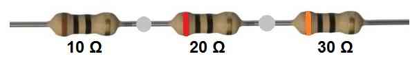
Assume you have three resistors with resistances of 10, 20, and 30 ohms. For a series connection:
We connect the 3 resistors one after the other as shown in the above figure.
The total series resistance can be measure across the ends of the series connection using a Ohm meter or can be calculated as I have explained below.
According to Ohm's law the total resistance of the series resistors can be calculated simply by adding the three resistor values.
R(total) = 10 + 20 + 30 = 60 ohms is the total resistance of the circuit.
Connecting Resistors in Parallel:
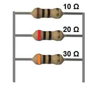
Let's say you have three resistors with values of 10 ohms, 20 ohms, and 30 ohms. In order to connect them in parallel, you will need to follow the below shown steps:
Connect all left side ends together, and then connect all the right side ends together, as shown in the above figure.
You can measure the parallel resistance value using an Ohm meter by connecting the ends of the resistances with the meter probe.
Alternatively, using the standard formula, the total resistance of the parallel circuit could be calculated as the reciprocal of the sum of the reciprocals of the individual resistances:
1/Rp(total) = 1/10 + 1/20 + 1/30 = 5.45 ohms.
Combination of Series and Parallel:
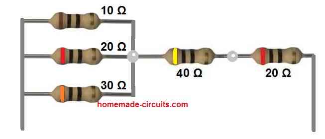
Now, let's assume we have four resistors with values of 10 ohms, 20 ohms, 30 ohms, and 40 ohms. To connect them in a combination of series and parallel we do the following setup
First we connect 3 resistors in parallel, meaning we connect the 10 ohm, 20 ohm and 30 ohm in parallel.
Then we connect a 40 ohm and a 20 ohm resistor in series and join this series connection with the above parallel setup.
To solve this series, parallel combination, we first solve the parallel configuration using the following formula:
1/Rp(total) = 1/10 + 1/20 + 1/30
R(total) = 5.45 ohms
Once the parallel combination is solved, then we solve the series combination using the following formula:
Rs(total) = 20 + 40 = 60 ohms.
Now, looking at the diagram it is obvious that the 5.45 ohms value of the parallel resistors is in series with the above 60 ohm resistor.
Therefore, we now simply add the 5.45 ohm with the 60 ohm to get the final result of the series, parallel combination, in the following manner:
R(total) = 5.45 + 60 = 65.45 Ohms
If you connect an ohm meter probes to the parallel end and the series end of the above combination, you will get the same value as obtained from the above calculation.

Questions & Answers
Thanks Swagatam;
However we had a correspondence which was also at this page down below 5 months ago and you had advised this “However we have to select a bulb whose power rating is lower than the power rating handling capacity of the circuit output device.” but this time you offer 200 w bulb that is higher than the source so I am confused or something that I miss?
Suat, if it is lower, then your LED TV will look very dim, so now i confirm that the series bulb rating should be higher than the LED TV wattage…at least by two times…
Hi Swagatam;
As known that for the short circuit safety precaution a serial bulb is used. My tv is 100-220V 75W can I use a serial 220V 10 W led bulb for the purpose?(12 pcs leds inside)
Hi Suat,
Yes you can do it for ensuring a longer life for the LEDs and the TV. But LED lamp will not work, you will need an incandescent, filament type of bulb, rated at 200 watts.
Hi Swagatam;
My tv has 3 strips of the leds and each strip has the 6 pcs of the leds so total leds quantity is 16 leds in the tv back panel. Tv power board label shows the led voltage output is 117V. But when i check the led voltage output of the power board it is only 68 V since the some of the leds are defective. whereas when i apply the about 32 V to the one firm strip (6 leds), 32 v is enough to light them and the current is about only 40 mA. i would like to test the led driver with a 2K4 ohm 4W dummy resistor.
(32* 3 strips = 96 V R= 96/0,04 =2K4 W=96*0,04=4 W)
However need your advice on the matter if possible?
Hi Suat,
If your 6 LED strips are in series (6 * 3) then yes, your calculation is correct. You can use 2.4k as the limiting resistor.
Hi Dear Swagatam;
Ref. to the short circuit tests they are used to connecting a serial bulb to the circuits. I watch the tv repair videos by master Tevz on the Youtube and he uses the resistor in place of the fuse and instead of a serial bulb while intial test of the repaired tv. If we assume that the tv is 220V and 160W so then which value of the resistor (both ohm and watt) we should prefer could you please tell me about that?
Hi Suat,
A series bulb is the right way to test the short circuit condition of any circuit, because the bulb will light up and become a high value resistor only when a short circuit current is detected, so the brightness of the bulb will directly indicate the condition of the circuit output. A resistor cannot provide this facility, so a resistor is not an appropriate option for such applications.
However we have to select a bulb whose power rating is lower than the power rating handling capacity of the circuit output device.
Thanks Swagatam for the kind responce. There was no gate voltage from the driver ic then I shorted the mosfet drain and source for led TV lights
(There are 91 leds and about 230V) I also used a serial bulb for safety checking.
The bulb is not OFF or not ON but it blinks. Could you please tell what that means?
Hi Suat,
Is the bulb blinking after shorting the MOSFET D/S, or without shorting it.
at the initial test at first I had shorted the 5V and stdby pins and the bulb lighted very short and then it was OFF but as soon as I shorted the mosfet drain with the gnd then the bulb was blinking. However after sending the message I retested and this time it blinks even the mosfet drain is not short with the gnd.
The bulb is supposed to light up constantly once the MOSFET is shorted because the MOSFET is main switching element which handles the full power.
If the bulb is blinking even while the MOSFET is shorted (disabled) then it is so confusing, because now the question is then which part is controlling the lamp blinking or the lamp power?
Not sure until we see the full schematic diagram.
Hi Swagatam;
After the below messages I used the 110AC appliance (air fryer) and 170uF capacitor and a 5 Ohm NTC in serial connected under the 220AC applied voltage as you had advised. After the test I see that the opening screen (start/stop button light) and warning signals(a few beeps sound) are OK. And I measure about 120V DC over the capacitor. However whenever I push the start button, I see the screen for a while (about 5 seconds) and then the screen disappears and I see about 260V over the capacitor. Would you please do a comment on the matter?
Hi Suat,
It seems there’s some internal smart cut-off circuitry which is detecting the momentary high voltage input and disconnecting the supply to the air fryer…that means this idea might not work for your device.
Thanks Swagatam and I am sorry after sending the message I have seen (at the youtube) that the value of the current capacity of the NTC 5D-11 is for 4A on which I had tought that it was 11A. So I am going to try to test it one more time with the 10A NTC. And if it has no higher risk I may try it for a very short period without the NTC.
No problem Suat! If you use a 150uF/400V cap then you can check it without an NTC, because 150uF will restrict the current to 7 amps.
But still you can try with a 10 amp NTC and check the results…
Hi Mr. Swagatam;
I have the heater resistor (as a part of the airfryer) and it’s specs.: 120V AC 1000W (8,5A) and about 14,5 Ohm. I need to use this resistor with the 220V AC. And if I have not made a mistake I should use 400V 0,002 mF(2000pF) serial capacitor to run it. (As per your advice we had used 4 mF serial capacitor for the 120V fan motor) but this time the current ratio is too high. So I need your advice / opinion please?
Hi Suat,
As a rule of thumb, a 1uF/400V capacitor allows around 50 ma current, so 8.5/0.05 = 170uF
So to limit the current to 8.5 amps, the capacitor value should be around 170uF/400V non-polar.
Thanks Swagatam, so it seems to buy 220V 1000W new heater resistance is more reasonable. Have nice weekend
No problem Suat, yes, buying a new 220V heater coil looks more affordable…
Sorry Swagatam this question may be unpredictable before the practise but instead of modifying / changing the parts one by one, is it possible to apply 220V AC directly to the input of the equipment by using the 170uF capacitor in serial? If it is tolerable so then it may be affordable. P.S.: The Airfryer itself is 120V 1000W too.
Hi Suat,
According to me, yes, you can connect the 220V to the load through the series 170uF capacitor, without anything else in the middle.
Just make sure the capacitor is non-polar, and preferably first try with a 150uF.
Swagatam as you advised I have tried the circuit by using 145uF (50+50+45 three capacitors parallel connected) and used 2A Fuse for the safety measurement. I have not used any termistor (10A hard to find at the market) or varistor . The result was very rejoicing and successful. Now I will remove the 2A fuse and replace 10A fuse. I am ready to test it with the 170uF capacitor and to test it’s 8A heating element. Accordingly I remain for your final advices if there is. with my special thanks and gratefulness
That’s great Suat, glad it is working for you.
But the NTC is very important and you must consider using it, you can use a 20 amp NTC instead, or use two 10 ohm/5amp NTCs in parallel.
Sorry Swagatam but I am not able to comprehend the matter on the
NTC current value? You have advised 2 different current value as the 10A(2* 5A as parallel connected) and 20A at your above message.
However my appliance power consumption is about 10A. Could you please confirm on if 20A is also can be OK for the 10A appliance?
Hi Suat,
Your appliance is rated at 8.5 amps, so a 10 amp NTC should be Ok, but if you cannot get 10 amp NTC, then you can also use a 20 amp NTC.
Hi Mr Swagatam;
In case we have two cables and their thickness and the length are equal but one is stranded type and other is single core. then which one is more resistant against the heat?
Hi Suat,
The standard cable which has multi-strand wire will generate less heat compared to a single core wire, so the multi-strand wire will be more efficient.
Hi Swagatam;
Let’s say we have 2 resistors of 100 Ohm and their wattage value are of 1/4 watts. When we connect them in parallel so then they would be as single resistor like with the value of 50 ohm however their wattage would be remain same as 1/4 watts or double as 1/2 watts?
Best Wishes
Hi Suat,
The wattage would become double, 1/2 watts.
thanks swagatam. We have the ordinary potentiometer at the market and i think they are called also universal hub single variable resistor. Neverthless it is not being mentioned about their wattage. For instant i have got 5K pot so please advise their wattage and if it is possible to connect them in parallel?
Best Wishes
Hi Suat, the ordinary pots are rated not more than 1/2 watt.
If you want to add them in parallel then you will have to make sure they are GANGED, meaning their wiper knobs are tied with each other so that they rotate exactly in a synchronized manner.
Hi Swagatam;
I have been seeing the videos about making your own resistor. As known sometimes hard to find cement resistor at lower ohm value like 0,1 ohm and sometimes they are very expensive. It is possible to make them at home by defining its ohm value and wattage and which material is more poductive i.e. copper graphite (pencil core) or chrome wire?
Best Wishes.
Hi Suat,
Sorry, I have no idea about this concept so not sure about it. I will have to investigate about it.
hello, good afternoon. I have a question, I have to feed a 12 vdc relay from a 31 vdc voltage. Now the question is, can I put a resistive divider instead of using a regulator for example lm7812… Thank you very much in advance.
A resistive divider might drop too much current which might not be sufficient for the relay to operate. You will have to use a 7812 IC or step down buck converter.